Boumatic StepMetrix Manual

StepMetrix™
(U.S. patent 6,699,207)
Installation, Operation Maintenance & Service Instructions
Instructional Content and Purpose
These instructions aim to aid those responsible (outlined und er
“Responsibilities”) for installing, operating , maintaining,
troubleshooting, and servicing this product.
Responsibilities
Procedures in these instructions are to be perfor med according to
applicable codes (state, local, and other) by the person(s) qualified
(licensed, if applicable) to do so—that is:
• Welding must be done by a qualified welder.
• High-voltage AC pow er wiring must be done by a qualified
(licensed) electrician in compli ance with the latest edition of
the ANSI/NFPA Standard 70, National Electrical Code, (USA)
or either LVD 2006/95/EC or EMC 2004/108/EC (Europe) and
in compliance with the local wiring codes as applicable.
• Other installation, major maintena nce, and service w ork must
be done by an authorized BouMatic dealer.
• Product/system checkout and troubleshooting steps are to be
performed by an authorized BouMatic dealer.
• Deviation from these instructions could affect product
performance or create a haza rdous situation. Under n o
circumstances will BouMatic be responsible for an y problems
caused in whole or in part by any deviation from the
procedures specified
in these instru ctions
without prior written
approval from
BouMatic.
• Operation steps ma y
be performed by the
owner/operator once
the dealer or
technician has
successfully finished the p roduct/system checkout. Th e
owner/operator is responsible for prop erly operating,
maintaining, and monitoring the product/s ystem to ensure that
it works properly.
P.O. Box 8050
Madison, WI, 53708-8050
USA
Telephone: (608) 222-3484
Fax: (608) 222-9314
Remicourt 31, Rue Jules Melotte
B 4350 Remicourt
Belgium
Telephone: +32 (0)19 544 266
Fax: +32(0)19 545 544
www.boumatic.com
Close compliance with the procedures herein is essential for the
owner to get maximum benefit from the product/system.
Disclaimers
No warranties are contained in th ese instructions. The division of
responsibilities, stated above, i s a general re minder of th ose
provisions in the applicable deal er contract and does not chang e
any agreement between BouMatic and the deale r. Information in
these instructions is not all-inclu sive and cannot cover all unique
situations.
Introduction ........................................................................................ 2
1. Preparation ..................................................................................... 2
1.1 Verifying Part and Tool Requirements ..................................... 2
1.2 Reviewing Installation Specifications ....................................... 2
1.2.1 StepMetrix Cow Traffic Guidelines.................................... 2
1.2.2StepMetrix Sensor Module Location .................................. 3
1.2.3 StepMetrix Controller Location.......................................... 3
1.2.4 Communication ................................................................. 3
1.2.5 Wiring................................................................................ 3
1.2.6 Dairy PC............................................................................ 4
1.2.7 Network Controller ............................................................ 4
1.2.8 SMX ISO ID Site Evaluation ............................................. 4
1.3 Reviewing Personal Safety Instructions................................... 5
1.3 Reviewing Personal Safety Instructions................................... 6
2. Installation....................................................................................... 6
2.1 Installing the StepMetrix with a BouMatic ID System............... 6
2.1.1 Installing the StepMetrix ID Antenna................................. 6
2.1.2 Installing the StepMetrix Sensor Module .......................... 7
2.1.3 Installing the StepMetrix Step-Up ..................................... 7
2.1.4 Installing the StepMetrix Step-Down................................. 7
2.1.5 Installing the StepMetrix Positioning Rails ........................ 8
2.1.5 Installing the StepMetrix Positioning Rails ........................ 9
2.1.5 Installing the StepMetrix Positioning Rails ........................ 9
2.1.6 Installing the StepMetrix Controller ................................. 10
2.1.7 Wiring the Power Supplies and StepMetrix Controller .... 11
2.1.7 Wiring the Power Supplies and StepMetrix Controller .... 11
2.1.7.1 Load Cell to StepMetrix Controller Connections...... 11
2.1.7.2 StepMetrix ID Connections ...................................... 15
2.1.7.3 Communication........................................................ 15
2.1.7.4 StepMetrix Controller Setup..................................... 15
2.2 Installing StepMetrix with ISO ID............................................ 15
2.2.1 Installing the StepMetrix Sensor Module ........................ 15
2.2.2 Installing the StepMetrix Step-Up ................................... 16
2.2.2 Installing the StepMetrix Step-Up ................................... 17
2.2.2 Installing the StepMetrix Step-Up ................................... 17
2.2.3 Installing the StepMetrix Step-Down............................... 17
2.2.4 Installing the StepMetrix Positioning Rails ...................... 17
2.2.5 Installing the StepMetrix ISO ID antenna ........................17
2.2.6 Installing the StepMetrix ISO ID Controller ......................18
2.2.7 Wiring the Power Supplies and StepMetrix ISO ID
Controller ...............................................................................19
2.2.7 Wiring the Power Supplies and StepMetrix ISO ID
Controller ...............................................................................19
2.2.7.1 Load Cell to StepMetrix ISO ID Controller
Connections .....................................................................19
2.2.7.2 Synchronization of HDX readers ..............................23
2.2.7.3 StepMetrix ISO ID Connections and Tuning ............23
2.2.7.4 Communication ........................................................23
2.3 StepMetrix System Configuration ...........................................23
2.3.1 Installing StepMetrix User Interface Software .................23
2.3.2 Unit Names......................................................................23
2.3.3 System Setup ..................................................................23
2.3.4 Dairy Setup ......................................................................23
2.4 StepMetrix Performance Tests ...............................................23
2.5 StepMetrix Calibration ............................................................25
2.5.1 Pre-Calibration Steps.......................................................25
2.5.2 StepMetrix Calibration Wizard .........................................25
3. Features ........................................................................................26
4. Operation .......................................................................................26
4.1 Understanding Basic StepMetrix Parts ...................................26
4.2 SMX™ Scores ........................................................................27
5 Troubleshooting .............................................................................28
6. Maintenance ..................................................................................32
6.1 StepMetrix Controller. .............................................................32
6.2 StepMetrix sensor module ......................................................32
7. Service...........................................................................................32
7.1 Load Cell.................................................................................33
7.2 ID Control ................................................................................33
7.3 Fan ..........................................................................................34
7.4 Hard Drive...............................................................................34
7.5 Load Cell Signal Conditioning Board ......................................34
7.6 Control Assembly ....................................................................34
7.7 Dealer Service Schedule.........................................................35
StepMetrix™ Installation Instructions 9E-864C
1

9E-864C StepMetrix™ Installation Instructions
2
Introduction
Lameness caused by injury or disease is a majo r
cause of fin ancial loss to the dairy owner. The
BouMatic StepMetrix system monitors hind leg
and hoof soundness in dairy cattle, providing
dairy operators early warning of hoof or l eg
problems that cause economic loss. StepMetrix
detects cows that are lame in the hind legs (the
most common form of lameness) a s they retur n
from the milking parlor. It can detect cows which
look sound, but have hoof problems and are sub-
clinically lame. StepMetrix enables “lameness
trend tracking” which assesse s lameness trends
within individual cows, groups and the herd.
StepMetrix calculates SMX™ scores of hin d
limbs every time a cow walks over t he
StepMetrix sensor module. The SMX score is a
numerical point system, unique to t he StepMetrix
system, indicating so undness or lameness.
StepMetrix provides an efficient, automatic
lameness detection system for mo nitoring cow
body condition and health. It dete cts early onset
of lameness, allowing early treatment. Early
detection helps to reduce the loss of milk
production and body weight, which are
associated with lamen ess. It can also provi de
useful information indicating the need f or
management changes for the cow, lot or herd.
1. Preparation
1.1 Verifying Part and Tool Requirements
To prepare, ensure that you have the follo wing
(depending on whether your Step Metrix installation
uses a Bo uMatic or ISO [Internatio nal Standards
Organization] ID antenna):
Product Parts Quantity per Single StepMetrix Unit
StepMetrix sensor module .................................................. 1
StepMetrix steps (step up + step down) ............................. 2
StepMetrix LH positioning rails ........................................... 2
StepMetrix RH positioning rails........................................... 2
StepMetrix controller........................................................... 1
StepMetrix packed parts ..................................................... 1
StepMetrix antenna ............................................................ 1
StepMetrix ID antenna shield.............................................. 1
StepMetrix software............................................................ 1
If something is missing, contact the
BouMatic Customer Service Department
immediately.
Dealer-Supplied Parts Quantity
2,3 Stranded wire, type TW insulated,
14 AWG (1.94 mm²) ....................................................a/r
2,3 Conduit fittings and fasteners......................................a/r
2,3 ¾” SCH40 PVC pipe, elbows, tees ...............................a/r
CAT 5E cable....................................................................a/r
Ethernet communication hub ............................................a/r
Dealer-Supplied Miscellaneous Parts Quantity
2,3 Wire nuts ......................................................................a/r
Cable ties ..........................................................................a/r
A small wooden screw driver or one with a plastic shaft ...a/r
Note: Abbreviation a/r means, “as required”
Notes
1. Part available from BouMatic Equipment catalog
2. Part must com ply with NEC; state, and/or local code
standards.
3. Parts must be CSA approved if installed in Canada
4. See subsection 1.2.4 for details explaining the n eed for this
part.
Other literature referenced in these instructions Section (§)
9P-476, Lighting Arrestor installation Instructions .......§1.2.5
9ES-768, ID Controller Installation Instructions…….......§1.9
9E-867, Ethernet Communications Instructions ............1.2.4
9E-892, SMX ISO ID Site Evaluation Instructions.......§1.2.8
1.2 Reviewing Installation Specifications
Plan the in stallation according to the following
guidelines:
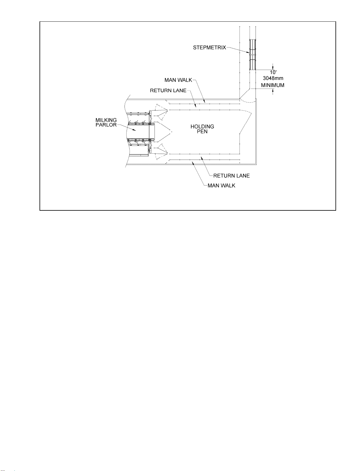
1.2.1 StepMetrix Cow Traffic Guidelines
A training period is always necessary when
StepMetrix is first installed on a dairy. Cows will need
several consecutive passes over the platform befo re
they walk with a relaxed gait. The physical installation
of the StepMetrix is very important. If the device i s
installed in a steep return alleyway, co ws may move
too quickly across the platform, resulting in a l ower
percentage of cows receiving an SMX score. Whe n
this location is the only a vailable option, it may be
necessary to install a n additional short platform at
least 10’-15’ (3m – 4.5m) away from the entrance at
the StepMetrix to both sl ow the cows down as they
cross the platform and to keep sufficient space
between cows. Cows walking over the system with a
normal walking gait will maximize the benefits of t he
StepMetrix system.
Do not push cows through the StepMetrix or allow
them to bun ch up a s they cross the platform. Th e

cows must walk consistently over th e platform with
their normal walking gait for all milkings.
Research has shown that cow m ovement through
alleyways will be sped whe n solid white sidewalls are
installed. The alleyway areas should also have
excellent lighting to facilitate norm al cow movem ent.
The alleyway leading onto the StepMetrix should al so
have solid plastic walls. The shi elding should extend
for 5 to 10’ (1.5 – 3m) past the exit end of the
StepMetrix Step down platform. The plastic shielding
should be in stalled from approximatel y 1’ (30 cm ) of
the ground to a total of 5’ (1.5 m) off the floor. If gates
are used to narro w a co w movement alleyway, the
gates should also h ave the same white pla stic
shielding. The goal is for cows to see the rear end of
a herd-mate moving cal mly and sl owly through the
shielded alleyway, which will encourage them to walk
in the same calm, relaxed manner.
An additional technique to improve single file cow
movement is to install narrow rubber mats imbedded
at floor level to enco urage cows to mo ve in a singl e
file into the exit alleys. The ru bber flooring can be
wide at the e xit of the parlor and then narrow down
toward the entrance of the exit alley whe re the
StepMetrix is installe d. The goal i s to make it m ore
comfortable for the co w to be in sing le file at the
StepMetrix location.
1.2.2StepMetrix Sensor Module Location
• The StepMetrix sensor module must be installed
in an area where cows walk in a single file after
milking so that only one cow can walk on th e
sensor module at a time at their normal pace. The
breezeway or an exit all eyway of th e milking
parlor is an ideal location.
• The StepMetrix should be installed as far a way
from the mil king parlor as possible in order to
avoid groups of cows walking through the system
in a mass.
• The StepMetrix should be installed in a location
where the cows will leas t likely to be pushed
through the system. The cows must be allowed to
move through the syste m one at a time a t a
normal pace.
• The StepMetrix must be installed in a location
where all the cows ca n walk thro ugh the system
after every milking
• The sensor module must be installed so that
there are no sharp turns, high step s or othe r
obstacles at least 10 feet (3m) before and 10 feet
(3m) after the system.
• The sensor module must be in stalled in an area
with easy access to water for re gular cleaning.
Automated flushing is ide al for kee ping manure
cleaned from underneath the sensor module.
• If there is a footbath, it must be at lea st 20 feet
(6m) before the StepMetrix step up or 20 fe et
(6m) after the StepMetrix step-down.
• The sensor module must be in stalled with the
StepMetrix step up and StepMetrix step down in
place.
• Recommended StepMetrix installation locations
are shown in Figures 1-4.
• In order to get SMX™ scores from all of the cows
passing through the sensor module, every effort
must be ma de to avoid crowding of the cows
before the step up and after the step down.
• Depending on the layout of the dairy, more than
one StepMetrix may be required in order to collect
data from all of the cows.
• The floor must be leveled before installation of the
StepMetrix sensor module.
• The water draining systems should be such that
the sensor module is not submerged in the water
at any time.
1.2.3 StepMetrix Controller Location
• The StepMetrix controller must be in stalled on
non-vibrating posts or a wall.
• The controller can be lo cated 8-10 fe et (2.4 to
3m) above ground level. It needs to be accessible
for troubleshooting.
• The controller must be installed within 58 inches
(1500 mm) of the top of the StepMetrix BM ID
antenna and within 70 inches (1800 mm) from the
ISO ID antenna furthest from the controller.
• The load cell cables must not be shortened.
Splicing the cables will adversely affect the
performance of the StepMetrix.
• The controller must be located on the same side
as the load cell conduit locations.
1.2.4 Communication
• A CAT 5E communi cation cable should run from
the controller(s) to the dairy PC.
• The CAT 5E cable must be run in conduit, and
must be no more than 300 feet (90 m) in length.
• A dedicated Ethernet connection to dairy PC from
a StepMetrix controller(s) is required.
• Refer to B ouMatic Ethernet Communications
Instructions 9E-867 for further details.
1.2.5 Wiring
• To operate properly, the controller requires 1 4
AWG (1.94 mm²) minimum input po wer stranded
wires to keep voltage drops to a minimum.
• Keep wiring as sho rt as possible for the best
protection against voltage drop.
• Wiring must be routed through conduit for
protection and aesthetic purposes (we
recommend the use of PVC conduit). AC and DC
wiring must not be route d together in the sam e
conduit.
StepMetrix™ Installation Instructions 9E-864C
3
9E-864C StepMetrix™ Installation Instructions
4
1. StepMetrix location in an adjoining building or passageway (ideal location) l864_1
If routed together, the AC wires will couple
transients onto the DC wires (that is, the DC wires
will pick up electrical noise). Communication and
DC cables can be run in t he same conduit. Such
noise could lead to poor or intermittent operation
of any cont roller served by the powe r supply.
Though no distance restrictions apply to conduits
for AC and DC wi res perpendicular to o ne
another, parallel conduit for AC and DC wi res
must be a mi nimum of 12 inches (305 mm) from
each other to prevent transients from coupling.
• Memory: 512 MB RAM
• Hard Drive: 10 GB Hard Drive
• Data Storage: 100 MB
• Network: Ethernet connector (Optional second
Ethernet connector for additional network)
• Backup Device: Secondary Hard Drive for full
backup
• DVD – R for data and program storage
• CDROM – R for program only
1.2.7 Network Controller
If the dairy fa rm is equipped with a Pro Vantage 2050
Network Controller, the dairy operator must have
Version 2.1.41 or higher of EZ cow software
• This product requires uninterrupted AC power to
operate properly. To ensure that it will not operate
intermittently, we recommend that a qualified (or
licensed, if applicable) electrician evaluate the
load on the farm and barn electrical service
entrance before you install and use the
product/system to ensure that it will have
adequate power.
1.2.8 SMX ISO ID Site Evaluation
• A site evaluation must be p erformed for
StepMetrix installations using ISO ID antennas.
Any needed corrective actions must be take n
before the installation of the StepMetrix.
• Before connecting power to the sy stem parts, a
lightning arrestor must be installed on AC power
lines, main pole, and p ower panels serving
BouMatic automation equipment. Refer to th e
Lightning Arrestor instructions, 9P-476.
• Refer to site evaluation instructions 9E-892 when
performing the evaluation.
1.2.6 Dairy PC
• Operating System: Windows 2000
• Processor: Intel Pentium III or AMD Athlon
• Monitor: SVGA Monitor, capable of resolution
1024x768 and 16-bit color depth
• Pointing Device: Mouse or equivalent

2. StepMetrix location, parlor with a dual return lane l864_2
3. StepMetrix location, single return lane l864_3
StepMetrix™ Installation Instructions 9E-864C
5
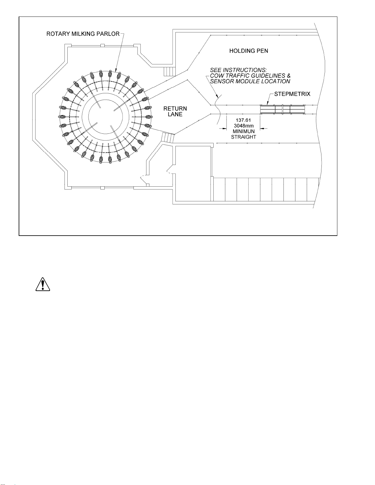
4. StepMetrix location, rotary parlor l864_4
1.3 Reviewing Personal Safety Instructions
To prevent possible bodily injury, foll ow the safety
instructions below and throughout this booklet.
— Warning ———————————⎯⎯⎯
9E-864C StepMetrix™ Installation Instructions
6
Turn off and lockout p ower to the po wer supply before
wiring the power for the St epMetrix. Failure to do s o could
cause serious injury or death.
2. Installation
The installation of the StepMetrix sy stem is a mult i-
step process. Follow installation steps as described in
the following sections.
— NOTE ———————————————————⎯⎯
• Review the instructions on page 1 under the
heading "Responsibilities" and perform only those
steps in this section that you are responsible for
performing.
• Review the personal safety message s and
installation specifications in Sectio n 1 and
instructions throughout this packet before starting
the procedure(s) in this section.
• Sides of the sensor module are defined as left
and right, as viewed from the direction of the cow
flow with respect to ¾” (19 mm) load cell conduit.
• Spacing of StepMetrix co mponents is critical for
best performance. Do not d eviate from
recommended dimensions
• It may be necessa ry to remove th e existing
railings in the installation area if the exit alleyway
is narrower than the recommended dimensions.
• The step assembly that is pla ced before the
sensor module will be referred as the StepMetrix
step up, while the ste p assembly that is pla ced
after the sensor module, will be referred as the
StepMetrix step down.
2.1 Installing the StepMetrix with a BouMatic
ID System
2.1.1 Installing the StepMetrix ID Antenna
— NOTE ———————————————————⎯⎯⎯
• The placement of the St epMetrix ID a ntenna and
StepMetrix controller determine the placement of th e
entire installation.
• The wire lengths of the load cell cables and ID antenna
cannot be ch anged; therefore the l ocation of th e
controller must be co nsidered before starting
installation.
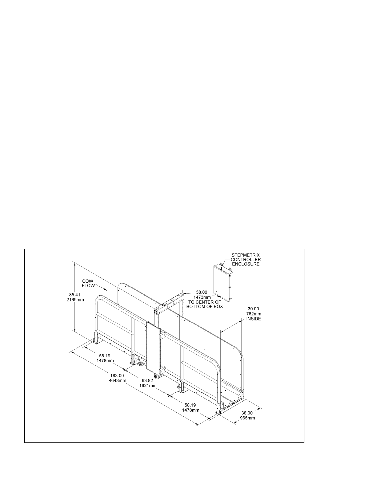
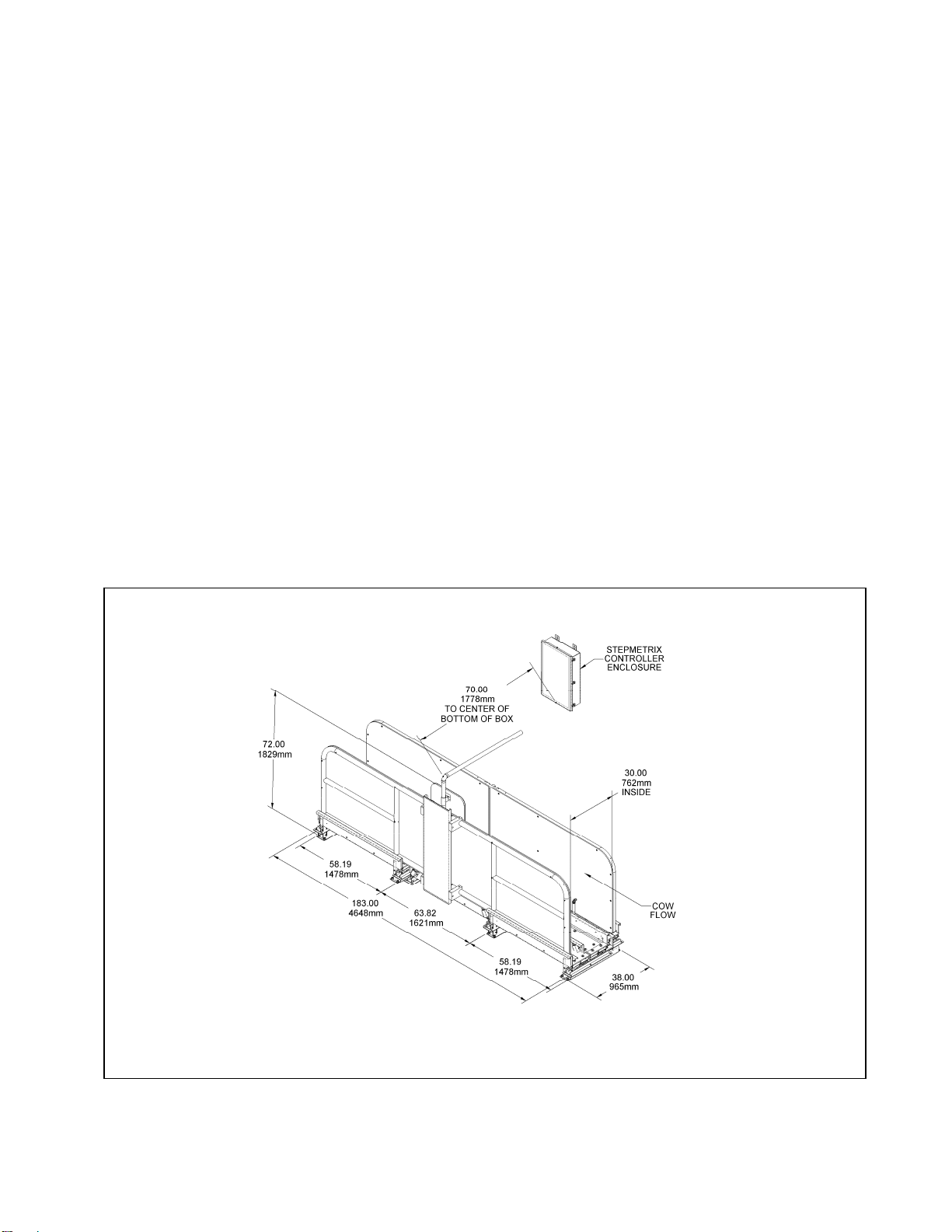
• The StepMetrix ID a ntenna must be inst alled at the
center of, a nd perpendicular to, the sens or module.
The top of the ID anten na where the conduit emerges
must be no more than 5 8 inches (1473 mm) from the
center of the bottom of the StepMetrix controller.
1. Secure the ID antenna to the floor usi ng 4 concrete
anchors (see Figure 6).
2.1.2 Installing the StepMetrix Sensor Module
1. Place the StepMetrix sensor module on the floor with
the conduits for the load cell cables on th e same side
as the conduit on the ID antenna.
2. Center the sensor module from side to side and end-to-
end in the StepMetrix ID antenna (see Figure 8).
3. Once sensor module is placed on the floor, walk on the
right and left sides of the se nsor module. If the sens or
module rocks, add sh ims underneath to stop the
rocking (see Figure 7). If the sensor module is fastened
to the floor without shimming to eliminate the rocking, it
will cause a twist in the sensor module that will hamper
the performance of the system and may cause
premature failure of the load cells.
4. Once the sensor module is neither rocking nor twisted,
fasten the sen sor module to the floor usin g concrete
anchors.
5. Walk on the sensor module after fastening the anchors
to make sure that the sensor module is not rocking.
2.1.3 Installing the StepMetrix Step-Up
1. Place the Ste pMetrix step-up on the flo or before th e
StepMetrix sensor module. Do not fasten the step-up to
the floor at thi s point. T he positioning rails need to be
assembled first (see Figure 9).
2.1.4 Installing the StepMetrix Step-Down
1. Place the StepMetrix step-down on the floor after the
sensor module.
2. Do not fasten the step-down to the floor at this po int.
The StepMetrix P ositioning rails must be assembled
first (see Figure 9).
5. The StepMetrix in place l864_5
StepMetrix™ Installation Instructions 9E-864C
7

9E-864C StepMetrix™ Installation Instructions
8
6. Mounting the StepMetrix™ ID antenna to the floor l864_6
7. Installin
g
the Ste
p
Metrix™ sensor module l864
_
7

8. StepMetrix sensor module dimensions and mounting locations l864_8
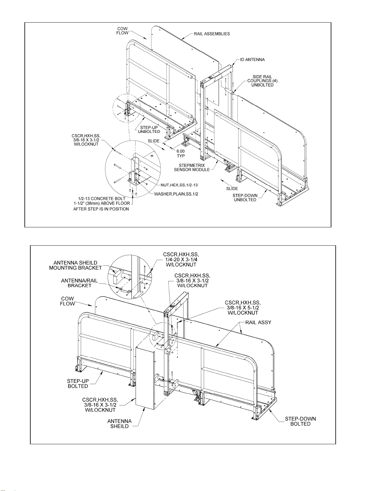
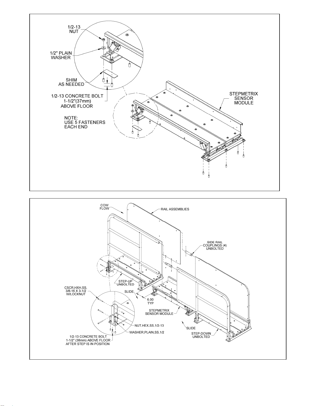
2.1.5 Installing the StepMetrix Positioning Rails
The StepMetrix positioning rails are used to center the
cows on the StepMetrix sensor module. To inst all
them, perform the following steps:
1. Place the p ositioning rails in the step up and step
down. Bolt the rails in place (see Figure 9).
2. Slide the step up and step down toward the s ensor
module, connecting the positioning rails together with
the plastic antenna supports as shown in Figure 9.
3. Position the step up and step down so there is a 1-inch
(25 mm) gap bet ween each step and t he sensor
module.
4. Walk on the step up an d step down to check for
rocking. If the step up or step do wn rocks place shims
underneath to prevent rocking.
5. Fasten the step up and the step down to the floor using
concrete anchors (see Figure 9).
6. Mount the antenna to the p ositioning rails using the
antenna rail bracket, as shown in Figure 10.
7. Attach the ant enna shield to the positioning rails us ing
the antenna shield-mounting bracket, as sho wn in
Figure 10.
2.1.6 Installing the StepMetrix Controller
— NOTE ———————————————————⎯⎯⎯
Route wiring through conduit for protectio n and aesthetic
purposes.
1. Select a location to mount the StepMetrix controller
where the ce nter of the bot tom of the b ox is no mor e
than 58” (1473 mm) from the t op of the Ste pMetrix ID
antenna where the flex conduit emerges. The controller
should be out of reach of cow traffic but accessible for
service.
2. Using suitable fasteners, mount the controller securely
to a stur dy structure or wall in a way that minimizes
vibration to the controller.
3. Connect the flex conduits from the Ste pMetrix ID
antenna and the se nsor module to the bottom of the
controller (see F igure 11).
StepMetrix™ Installation Instructions 9E-864C
9
9E-864C StepMetrix™ Installation Instructions
10
9. Installing the positioning rails, StepMetrix step-up and StepMetrix step-down l864_9
10. Attaching the antenna shield to the positioning rails l864_10

2.1.7 Wiring the Power Supplies and StepMetrix
Controller
—ATTENTION —————————————⎯⎯⎯⎯⎯⎯
Do not apply DC power to c ontrollers served by the power
supply until all connections have been made between the
power supply and the controller(s). If po wer is applied to a
controller before all connections have been made, the
power supply may become overloaded, causing a circuit
breaker to tri p or ot her power supply damage to res ult or
possibly causing damage to products served by the power
supply.
4. Wiring from the power supply to the controller box must
be run in conduit using 14 GA (2.5mm2) wire for the AC
Ground, DC Common, 12V and 24V.
5. Turn the voltage adjustment on the 12 V power supply
counter clockwise. This is done to re duce power
dissipation in the enclosure.
6. Connect the AC Ground, DC Common, 12V and 24V to
the terminal block in controller.
— NOTE ———————————————————⎯⎯⎯
The following colors are recommended
AC ground Green or green/yellow if required
by code
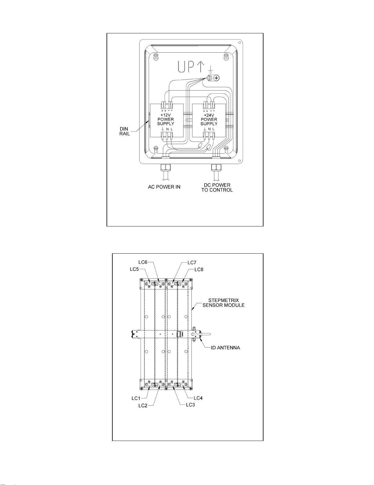
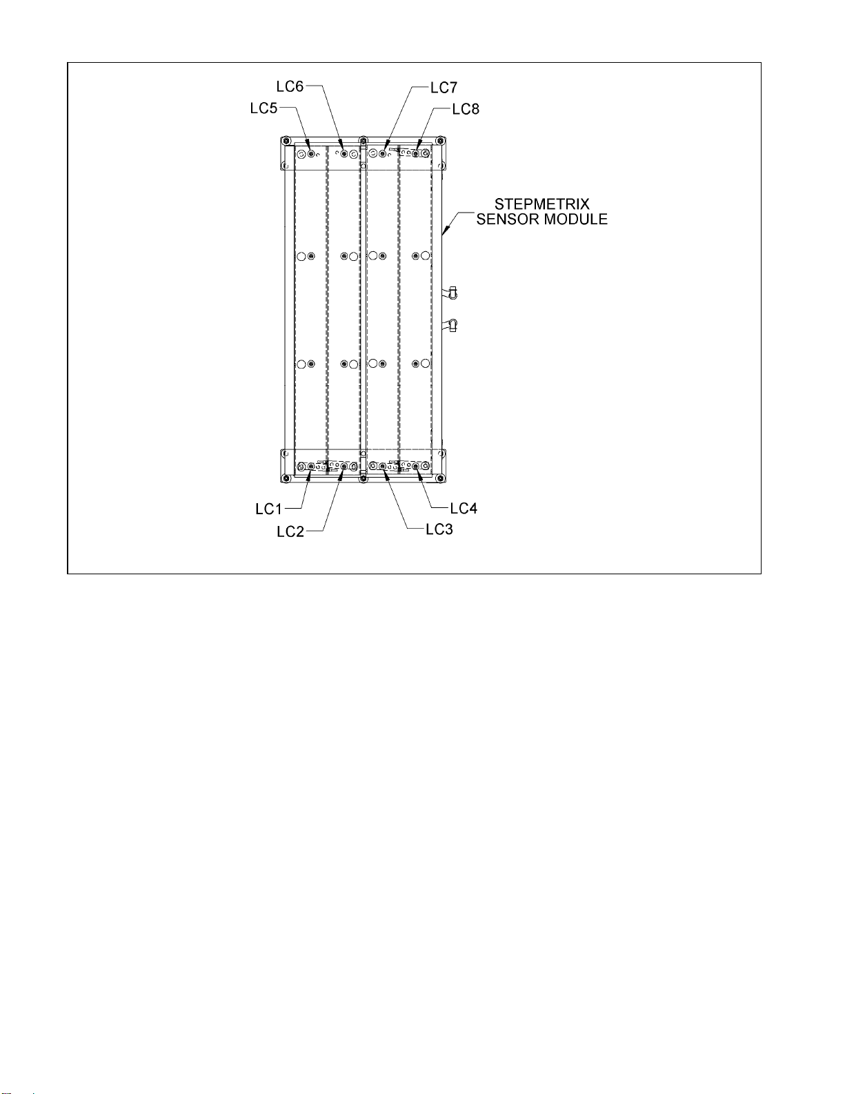
2.1.7.1 Load Cell to StepMetrix Controller Connections
• The load cells for the StepMetrix se nsor module
are numbered 1-8. They are numbered with
respect to the location of the ¾ ” (19 mm) conduit,
as shown in Figure 13.
DC common Black/white
+12 Volts DC Pink/white
+24 Volts DC Red/white
• Each load cell is connected to a connector on the
load cell signal conditioning board.
1. Mount the p ower supplies in the enc losure that’s
provided. Mount it in a dr y location no mo re than 5 0
feet (15 m) from the StepMetrix controller.
• The load cell signal conditioning board, located in
the StepMetrix controller, has fo ur 10-pin
connectors (J101 to J10 8), as shown in Figures
14 and 14a.
2. Connect the power supply to 220-240VAC, following all
applicable codes, as shown in Figure 12. • Connect individual load cell cables to the pins, as
shown in Figure 14a.
3. Connect DC Common between the 12V and 24V power
supplies. Use 14 GA (2.5 mm2) wire.
11. Installing the StepMetrix™ controller l864_11
StepMetrix™ Installation Instructions 9E-864C
11
9E-864C StepMetrix™ Installation Instructions
12
12. Wiring the power supply l864_12
13. Load cell locations l864
_
13

14. Wiring diagram label, P/N 3558769 l864_14
StepMetrix™ Installation Instructions 9E-864C
13

9E-864C StepMetrix™ Installation Instructions
14
14b. The control assembly l864_14b
14a. Load cell board l864_14a
2.1.7.2 StepMetrix ID Connections
Refer to I D controller instructions 9ES-768 when
installing the ID connections.
1. Connect the StepMetrix ID anten na receive and
transmit cables to the ID controller (see Figure 14).
2. The receive c able has small black, large black and
yellow wires. Connect the large black wire to pin 1, the
small black wire to pin 2, and the large yellow wire to
pin 3.
3. Connect the transmit cable, which has two black wires
bonded together, to the trans mit terminals of J1 in th e
ID controller.
4. Verify that there is a jumper wire from pin 2 to 5 of J5,
and that SW1is set to 1 and SW2 set to C.
2.1.7.3 Communication
For detailed networking instructions, refer to
BouMatic’s Ethernet Co mmunications instructions,
9E-867.
2.1.7.4 StepMetrix Controller Setup
1. Turn on power to the power supplies.
2. Tune the tra nsmitter on the ID co ntroller (Refer to I D
controller Instructions 9ES-768).
2.2 Installing StepMetrix with ISO ID
2.2.1 Installing the StepMetrix Sensor Module
1. Place the StepMetrix sensor module on the floor.
Locate the conduits for the load c ell cables on th e
same side that the Ste pMetrix controller will be
mounted.
2. Once the sensor module is placed on the floor, walk on
the right and left sides of th e sensor module. If the
sensor module rocks, add shims underneath to stop the
rocking (see Figure 16). If the s ensor module is
fastened to the floor without shimming to eliminate the
rocking, it will cause a twist in the se nsor module that
will hamper the performance of the s ystem and ma y
cause premature failure of the load cells.
3. Once the sensor module is neither rocking nor twisted,
fasten the sen sor module to the floor usin g concrete
anchors.
4. Walk on the se nsor module after fastening the anchors
to make sure that the sensor module is not rocking.
15. The StepMetrix™ with ISO ID system in place l864_18
StepMetrix™ Installation Instructions 9E-864C
15
9E-864C StepMetrix™ Installation Instructions
16
16. Installing the StepMetrix™ sensor module l864_19
17. Installing the positioning rails, StepMetrix step-up and StepMetrix™ step-down l864_20

18. Attaching the antenna shield to the positioning rails l864_21
2.2.2 Installing the StepMetrix Step-Up
1. Place the Ste pMetrix step-up on the flo or before th e
StepMetrix sensor module. Do not fasten the step up to
the floor at thi s point. T he positioning rails need to be
assembled first (see Figure 17).
2.2.3 Installing the StepMetrix Step-Down
1. Place the StepMetrix step-down on the floor after the
sensor module.
2. Do not fasten the step-down to the floor at this po int.
The StepMetrix p ositioning rails must b e assembled
first (see Section 2.2.4).
2.2.4 Installing the StepMetrix Positioning Rails
The StepMetrix positioning rails are used to center the
cows on the StepMetrix sensor module. To inst all
them, perform the following steps:
1. Place the p ositioning rails in the step-do wn and ste p
down. Bolt the rails in place (see Figure 17).
2. Slide the step -up and step-down toward the sensor
module, connecting the positioning rails together with
the plastic antenna supports as shown in Figure 17.
3. Position the step up and step-down so there is a 1-inch
(25 mm) gap bet ween each step and t he sensor
module.
4. Walk on th e step-up and step-down to check for
rocking. If the step up or step do wn rocks place shims
underneath it to prevent rocking.
5. Fasten the step-up and the step-down to the floor using
concrete anchors (see Figure 17).
2.2.5 Installing the StepMetrix ISO ID antenna
— NOTE ———————————————————⎯⎯⎯
The wire lengths of the load cell cables and ISO ID antenna
cannot be c hanged; therefore the location of the controller
must be considered before installation.
The StepMetrix ISO ID antenna must be i nstalled at the
center of, and parallel to, the positioning rails.
1. Position the ISO ID antenn a on p ositioning rails and
drill holes in t he ISO ID an tenna. Locate the hol es
within the area bordered by the groove in the antenna’s
surface, as s hown in Figure 18, detail A. T he antenna
must not be drilled outside this area. The top of the
antenna should be 72” a bove the floor. Drill h oles
through the plastic sheet of the p ositioning rails at the
center of the ID antenna. Mount the antenna using the
supplied hardware (see Figure 18).
StepMetrix™ Installation Instructions 9E-864C
17
9E-864C StepMetrix™ Installation Instructions
18
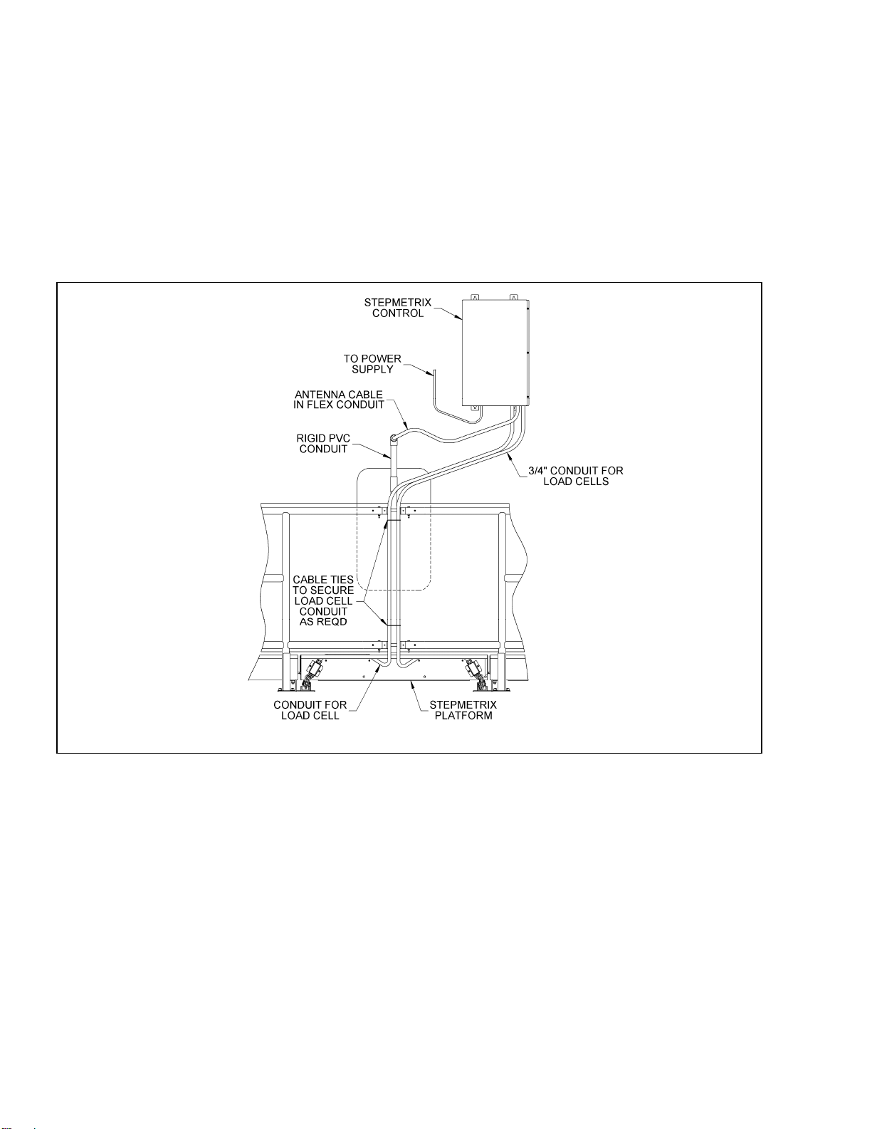
2. Install rigid PVC conduit (dealer supplied) to protect the
antenna cable from co w traffic and ro ute the cabl e to
the StepMetrix controller antenna (see Figure 18).
2.2.6 Installing the StepMetrix ISO ID Controller
— NOTE ———————————————————⎯⎯⎯
Route wiring through conduit for protectio n and aesthetic
purposes.
1. Select a location to mount the StepMetrix controller
where the ce nter of the bot tom of the b ox is no mor e
than 70” (1500 mm) from the top of the StepMetrix ISO
ID antenna. The controller should be out of reach of
cow traffic but accessible for service.
2. Using suitable fasteners, mount the controller securely
to a sturd y structure or wall in a way that allo ws the
least amount of vibration to the controller.
3. Connect the flex conduits from the Ste pMetrix ID
antenna and the se nsor module to the bottom of the
controller (see Figure 19).
19. Installing the StepMetrix™ ISO ID controller l864_22

20. Wiring the power supply l864_23
2.2.7 Wiring the Power Supplies and StepMetrix ISO
ID Controller
2. Connect the power supply to 220-240VAC, following all
applicable codes (see Figure 20).
—ATTENTION —————————————⎯⎯⎯⎯⎯⎯ 3. Wiring from the power supply to the controller box must
be run in conduit using 14 GA (2.5mm2) wire for the AC
Ground, 24 V and DC Common.
Do not apply DC power to c ontrollers served by the power
supply until all connections have been made between the
power supply and the controller(s). If po wer is applied to a
controller before all connections have been made, the
power supply may become overloaded, causing a circuit
breaker to trip or oth er power supply damage to result. It
may also cause damage to other products served by the
power supply.
4. Connect the AC Ground, DC Common, and 24V to the
terminal block in the controller.
2.2.7.1 Load Cell to StepMetrix ISO ID Controller Connections
• The load cells for the StepMetrix se nsor module
are numbered 1-8. T hey are numbered with
respect to the location of the ¾ ” (19 mm) c onduit,
as shown in Figure 21.
— NOTE ———————————————————⎯⎯⎯
The following colors are recommended:
AC ground Green or green/yellow if required
by code
• Each load cell is connected to a c onnector on the
load cell signal conditioning board.
DC common Black/white • The load c ell signal conditioning board, located in
the StepMetrix controller, has four 10-pin
connectors (J101 to J108), as shown in Figures 22
and 25.
+24 Volts DC Red/white
1. Mount the power supply in the enclosure that’s
provided. Mount it in a dr y location no mo re than 5 0
feet (15 m) from the StepMetrix controller. • Connect individual load cell cables to the pins, as
shown in Figure 22.
StepMetrix™ Installation Instructions 9E-864C
19
9E-864C StepMetrix™ Installation Instructions
20
21. Load cell locations l864_24
Table of contents
Other Boumatic Measuring Instrument manuals


