INTRODUCTION
Dear Valued Customer,
Thank you for choosing the Bowens Ringflash ro.
The Bowens Ringflash ro has been developed by working closely with professional photographers to create a product suitable for, and which meets the
standards of even the most demanding of todays professional studios. For details of all related Bowens products please contact your local distributor, a
list of which can be found at www.bowens.co.uk. In order to obtain the full benefit from your purchase please take a few moments to familiarise yourself
with this user manual.
Thank you,
Bowens International Ltd.
lease take time to read through and follow these safety instructions:
ALWA S
• be careful of and avoid placing the Ringflash ro cable where it can be tripped over.
• switch the pack on AFTER the Ringflash ro has been connected.
• ensure that the Ringflash ro cable connector is correctly fitted before using.
• remove the protective cover before use.
• turn OFF the pack, disconnect from the power supply, unplug the Ringflash ro and allow to cool down before attaching or removing any
accessories or reflectors.
• use with the protective glass cover attached.
NEVER
• place heavy objects on top of the Ringflash ro cables and avoid running them over sharp or hot objects.
• use the equipment with damaged cables. Have them replaced as soon as possible. NEVER attempt to repair them yourself.
• use in an environment where moisture, water vapour or inflammable liquids, vapour or materials may come into contact with the Ringflash
ro or pack. The flash output as well as modelling lamps can cause ignition of or damage to materials that may come into contact with the
Ringflash ro.
• obstruct the airflow around the Ringflash ro or pack.
GENERAL FEATURES
SAFETY INFORMATION
The Ringflash ro is designed for use with the all Bowens 20- in Quad socket generators
• Flash tubes with colour corrective UV coating.
• Adjustable modelling lamps with On/Off switch.
• Easy fitting of reflectors and accessories.
• Universal camera bracket.
• Can be used with light stand or camera stand.
• Incorporates handle for portable hand held use.
• Includes built-in thermal cut out. The cut out will only stop the Ringflash ro from flashing. If this occurs it is advised to turn off the modelling
and allow to cool for 10 minutes. Do not turn off the pack as the Ringflash ro fans will aid and speed up the cooling process.
1
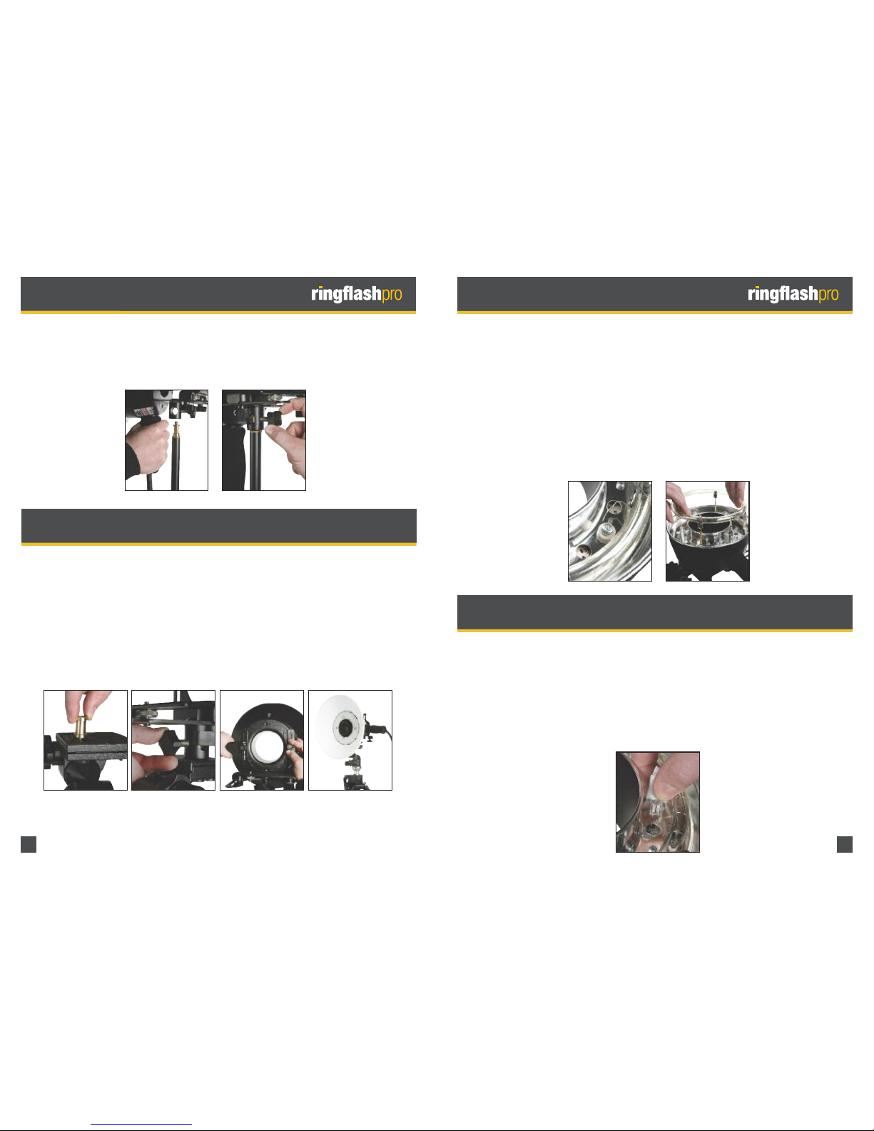
MOUNTING RINGFLASH PRO TOLIGHT
STAND
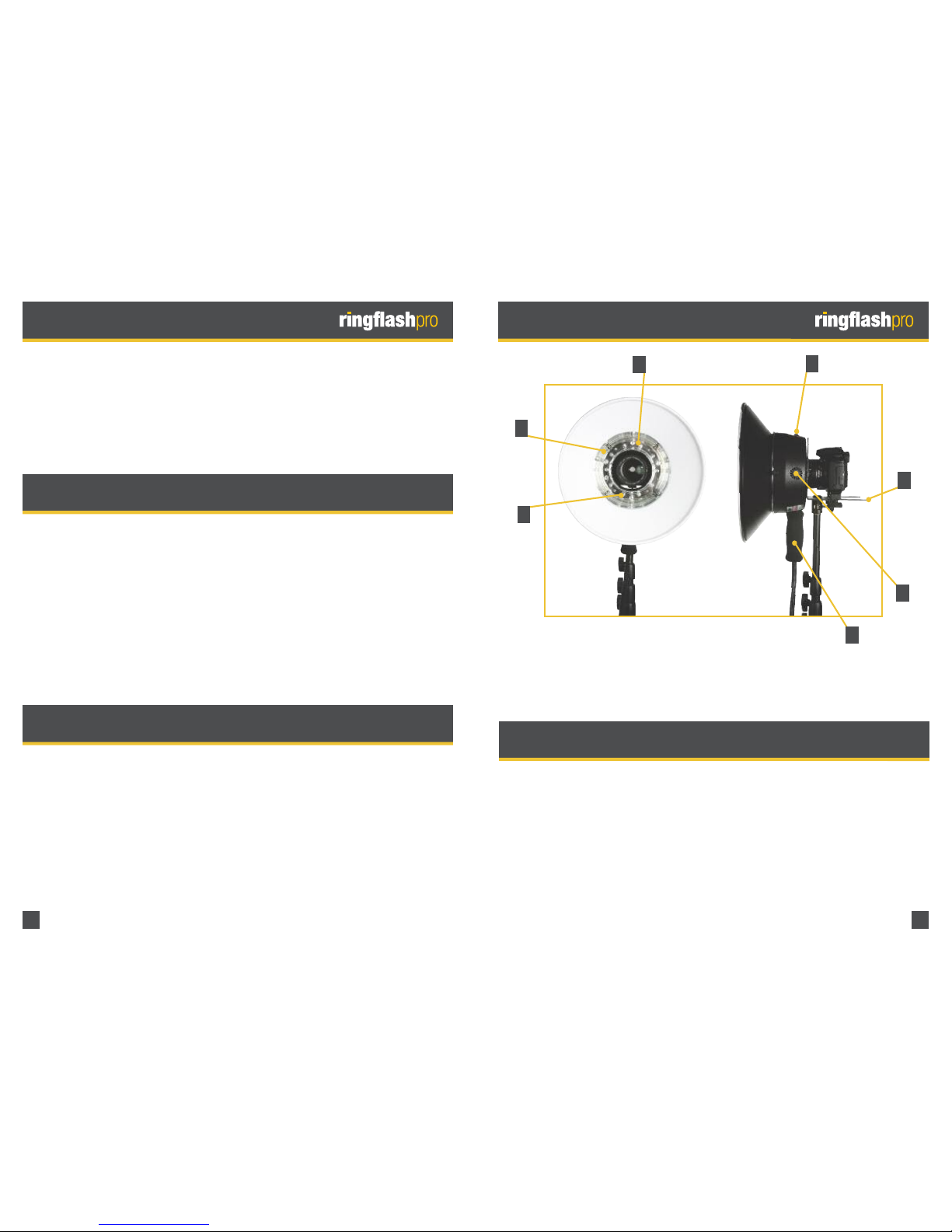
PRODUCT OVERVIEWINTRODUCTION
N.B. Ringflash ro shown with optional reflector
A.) Soft Grip Handle B.) Modelling On/Off Switch
C.) Camera Bracket D.) rotective Glass Cover
E.) Built-In Cooling Fan F.) Flash Tube
G.) Modelling Lamps
A
B
C
D
E
F
G
ITEMS PROVIDED INCARTON
1.) Ringflash ro 2.) Camera Bracket
3.) Camera Mount Thread 4.) 12 x Modelling Lamps
(Includes 10 plus 2 spare)
5.) Flash Tube 6.) Clear rotective Glass Cover
7.) Frosted rotective Glass Cover 8.) Brass Spigot
9.) 2 x Blanking lugs
2