manuals.online logo
Brands
  1. Home
  2. •
  3. Brands
  4. •
  5. Bowers & Wilkins
  6. •
  7. Subwoofer
  8. •
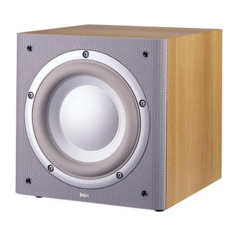
  9. Bowers & Wilkins Subwoofer ASWCM User manual

Bowers & Wilkins Subwoofer ASWCM User manual

Owner’s Manual
ASW CM
Figure 1
Figure 2
Figure 3
ASW CM Owner’s manual
English ...............................1
Français..............................4
Deutsch ..............................9
Español ............................13
Português ..........................17
Italiano .............................21
Ne erlan s .......................25
Ελληνικά .........................29
Русский...........................34
................................39
.............................42
Norsk...............................46
Svenska ............................47
Suomi...............................48
E60065-00
100-230V~ 50/60Hz 100W
SUBWOOFER
SURROUND CENTRE
L
R
FRONT
L
R
Decoder
No.2 No.
E60065-00
E60065-00
Figure 4
Figure 5
RIGHT LEFT
++
-
-
NO.2 NO.
L
R
SPEAKERS OUT
+
-
Pre-Amplifier Power Amplifier
L
LINE OUT
R
L
LINE IN
R
E60065-00
RIGHT LEFT
++
-
-
NO.2 No.
L
R
SPEAKERS OUT
+
-
Pre-Amplifier
L
LINE OUT
R
Power Amplifier
L
LINE IN
R
E60065-00
1
IMPORTANT
SAFETY
INSTRUCTIONS
Caution:
To re uce the risk of electric shock, o not
remove the back panel an o not expose the
apparatus to rain or moisture. No user-
serviceable parts insi e. Refer servicing to
qualifie personnel.
Explanation of Graphical Sy bols:
The lightning flash within an
equilateral triangle is inten e to
alert you to the presence of
uninsulate “ angerous voltage”
within the pro uct’s enclosure that
may be of sufficient magnitu e to
constitute an electric shock to
persons.
The exclamation point within an
equilateral triangle is inten e to
alert you to the presence of
important operating an
maintenance (servicing) instructions
in the literature accompanying the
appliance.
WARNINGS:
1Read Instructions – All the safety an
operating instructions shoul be rea before
the appliance is operate .
2Retain Instructions – The safety an
operating instructions shoul be retaine for
future reference.
3Heed Warnings – All warnings on the
appliance an in the operating instructions
shoul be a here to.
4Follow Instructions – All operating an
use instructions shoul be followe .
5Installation – Install in accor ance with
the manufacturer's instructions.
6Power Sources – This pro uct shoul be
operate only from the type of power source
in icate by the marking situate on the rear
panel. If you are not sure of the type of
power supply to your home, consult your
pro uct ealer or local power company.
7Grounding or Polarisation – The
appliance is not require to be groun e .
Ensure the plug is fully inserte into the wall
outlet or extension cor receptacle to prevent
bla e or pin exposure. Some versions of the
pro uct are equippe with a power cor
fitte with a polarise alternating line plug (a
plug having one bla e wi er than the other).
This plug will fit onto the power outlet only
one way. This is a safety feature. If you are
unable to insert the plug fully into the outlet,
try reversing the plug. If the plug shoul still
fail to fit, contact your electrician to replace
your obsolete outlet. Do not efeat the safety
purpose of the polarise plug. When using
an extension power-supply cor or a power-
supply cor other than that supplie with the
appliance, it shoul be fitte with the
appropriate moul e -on plugs an carry
safety approval appropriate to the country of
use.
8Power Cord Protection – Power-supply
cor s shoul be route so that they are not
likely to be walke on or pinche by items
place on or against them, paying particular
attention to cor s at plugs, convenience
receptacles an the point where they exit
from the appliance.
9Overloading – Do not overloa wall
outlets, extension cor s or integral
convenience receptacles, as this can result in
a risk of fire or electric shock.
10 Ventilation – The amplifier panel at the
rear of the pro uct forms part of the cooling
mechanism an must not be obscure by
placing the pro uct on a be , sofa, rug, or
other similar surface. Do not cover the
amplifier panel with any items such as
tablecloths, newspapers, etc. Ensure the heat
sink fins are aligne vertically to ensure
proper cooling. There shoul be a clear gap
of at least 50mm (2-in) between the back of
the pro uct an any wall or partition. If the
pro uct is place in a built-in installation,
such as a rack, bookcase or cabinet, proper
provision for air to circulate must be
provi e , either by a) 12mm (1
/2-in) clear
gap roun the top, si es an bottom of the
pro uct venting into the room or b) two ucts
of 150 sq cm (24 sq in) minimum cross
section from the room lea ing to slots
300mm (12-in) wi e x 50mm (2-in) eep at
top an bottom of the compartment, in line
with the gap behin the pro uct.
11 Heat – The pro uct shoul be situate
away from heat sources such as ra iators,
heat registers, stoves, or other pro ucts
(inclu ing amplifiers) that pro uce heat. No
nake flame sources, such as lighte
can les, shoul be place on the apparatus.
12 Wall or Ceiling Mounting – The
pro uct shoul be mounte to a wall or
ceiling only as recommen e by the
manufacturer.
13 Water and Moisture – To re uce the risk
of fire or electric shock, o not expose the
pro uct to rain or excessive moisture such as
in a sauna or bathroom. Do not use this
pro uct near water – for example, near a
bathtub, washbowl, kitchen sink, laun ry
tub, in a wet basement, or near a swimming
pool an the like.
14 Object and Liquid Entry – Never push
objects of any kin into this pro uct through
openings, as they may touch angerous
voltage points or short out parts that coul
result in a fire or electric shock. Never spill
liqui of any kin on the pro uct. Do not
place any object containing liqui on top of
the pro uct.
15 Cleaning – Unplug the pro uct from the
wall outlet before cleaning. The cabinet of
the subwoofer may be cleane by usting
with a ry cloth. If you wish to use an
aerosol cleaning spray, o not spray irectly
on the cabinet; spray onto the cloth. Remove
the grille first so that the cloth oes not
become staine , but be careful not to isturb
the rive unit. The grille itself may be
cleane using a soft brush.
16 Attachments – Do not use attachments not
recommen e by the pro uct manufacturer,
as they may cause hazar s.
17 Accessories – Do not place this pro uct
on an unstable cart, stan , tripo , bracket or
table. The pro uct may fall, causing serious
injury to a chil or a ult, an serious
amage to the pro uct. Use only with a
cart, stan , tripo , bracket or table
recommen e by the manufacturer or sol
with the pro uct. Any mounting of the
pro uct shoul follow the manufacturer’s
instructions an shoul use a mounting
accessory recommen e by the
manufacturer.
18 Moving the appliance – A pro uct an
cart combination shoul be move with
care. Quick stops, excessive
force an uneven surfaces may
cause the pro uct an cart
combination to overturn. Check
that there are no cables un er
the carpet that may be amage by the
spike feet. Do not walk the pro uct on the
spike feet as this may cause them to become
etache from the cabinet an cause
amage. Take care not to impale yourself
with the spike feet.
19 Non-use Periods – The power cor of
the appliance shoul be unplugge from the
outlet uring lightning storms or when the
apparatus is left unuse for a long perio of
time.
20 Servicing – Do not attempt to service this
pro uct yourself, as opening or removing
covers may expose you to angerous
voltage or other hazar s. Refer all servicing
to qualifie service personnel.
21 Damage Requiring Service – Unplug
this pro uct from the wall outlet an refer
servicing to qualifie personnel un er the
following con itions:
a When the power-supply cor or plug has
been amage .
b If liqui has been spille or objects have
fallen into the appliance.
c If the pro uct has been expose to rain or
water.
If the pro uct oes not operate normally
by following the operating instructions.
CAUTION
RISK OF ELECTRIC SHOCK
DO NOT OPEN
2
A just only those controls that are covere
by the operating instructions, as an
improper a justment of other controls may
result in amage an will often require
extensive work by a qualifie technician to
restore the pro uct to its normal operation.
e If the pro uct has been roppe , or
amage in any way.
f When the pro uct exhibits a istinct
change in performance – this in icates a
nee for service.
22 Replacement Parts – When replacement
parts are require , be sure the service
technician has use replacement parts
specifie by the manufacturer or have the
same characteristics as the original part.
Unauthorise substitutions may result in fire,
electric shock or other hazar s.
23 Mains Fuses – For continue protection
against fire hazar , use fuses only of the
correct type an rating. The amplifier is
esigne to operate with nominal mains
supplies in the range 100V to 230V AC, but
ifferent types of fuse are use , epen ent
on the mains voltage. The correct fuse
specification for each voltage range is
marke on the pro uct.
24 Safety Check – Upon completion of any
service or repairs to this pro uct, ask the
service technician to perform safety checks
to etermine that the pro uct is in proper
operating con ition.
25 Magnetic Fields – the pro uct creates a
stray static magnetic fiel . Do not place any
object that may be amage by this
magnetic fiel (eg catho e ray tube
televisions or computer monitors, au io an
vi eo tapes an swipe car s) within 0.5m
(2 feet) of the appliance. The appliance may
cause istortion of catho e ray tube images
beyon this istance.
Introduction
Thank you for purchasing a B&W ASW Active
Subwoofer.
Since its foun ation in 1966, the continuing
philosophy of B&W has been the quest for
perfect soun repro uction. Inspire by the
company’s foun er, the late John Bowers, this
quest has entaile not only high investment in
au io technology an innovation but also an
abi ing appreciation of music an the eman s
of film soun to ensure that the technology is put
to maximum effect.
This subwoofer has been esigne for Home
Theatre installations an to augment the bass
performance of full-range speakers in 2-channel
au io use. A ing the subwoofer to your system
not only exten s the bass to lower frequencies, it
improves the mi range clarity by re ucing the
low-frequency eman s on your existing speakers.
Please rea through this manual fully before
using the subwoofer. All soun installations
require some planning an experimentation if
you are to get the best out of the pro ucts use
an this manual will gui e you in this process.
As the subwoofer is connecte to the electricity
power supply, it is important that you familiarise
yourself with the safety instructions an hee all
warnings.
Keep this manual in a safe place for future
reference.
B&W pro ucts are istribute to over
60 countries worl wi e an we maintain an
international network of carefully chosen an
e icate istributors. If you have a problem,
which your ealer cannot resolve, our istributors
will be more than willing to assist you.
Unpacking
(figure 1)
The easiest way to unpack the subwoofer an
avoi amage is as follows:
• Open the carton flaps right back an invert
the carton an contents.
• Lift the carton away from the pro uct.
We recommen that you retain the packaging
for future use.
In a ition to this manual, the carton shoul
contain:
1 Subwoofer
1 Accessory pack containing:
4 Rubber feet
4 Spike feet
4 Lock nuts
1 International warranty ocument
A tour of the subwoofer
(figure 2)
1 Power/Stan by in icator
2 VOLUME control
3 LOW-PASS FREQUENCY control
4 MODE On/Auto/Stan by switch
5 Equalisation switch
6 LOW-PASS FILTER efeat switch
7 Phase switch
8 LINE IN
9 LINE OUT
10 LINK OUT
11 Fuse hol er
12 Power input socket
13 POWER on/off switch
Positioning the subwoofer
Because the subwoofer pro uces only low-
frequency soun s, positioning is less critical in
some respects compare to full-range speakers.
Directional information is much less precise an
you have more choice where to place the
speakers to goo effect. This sai , best results
are obtaine if the subwoofer is place between
the satellite speakers or in the vicinity of one of
them. If you use two subwoofers, it is best to put
one near each satellite speaker.
Placing the subwoofer behin the listeners, even
in surroun soun installations, generally gives
inferior imaging, but may be an acceptable
compromise if omestic consi erations ictate.
As with all speakers, the proximity of room
boun aries affects the soun . Bass is generally
increase as more surfaces come into close
proximity with the speakers. Unlike full-range
speakers, however, you can always restore the
correct overall system balance by a justing the
volume level of the subwoofer. The more boost
you get from the room, the less har the speaker
has to work; but there is a own si e. Corner
positions often excite more low-frequency room
resonances, making the bass more uneven with
frequency. There is no substitute for experiment
as all rooms behave ifferently, so try the
subwoofer in a variety of positions before
making a final ecision. A piece of music with a
bass line ascen ing or escen ing the musical
scale is useful for assessing the smoothness of
the bass response. Listen for exaggerate or
quiet notes. Having a separate subwoofer oes
enable you to optimise for room resonances
in epen ently from siting the satellite speakers
for best imaging.
If the subwoofer is to be use in a confine
space (eg in custom furniture), the space must be
ventilate to allow sufficient air to circulate an
cool the unit. Ask your ealer for a vice.
The subwoofer is supplie with four spike feet.
The spikes pierce through carpet pile, giving a
firm support irectly to the floor surface without
crushing the pile.
If the unit is to be place on a vulnerable
surface, such as a woo en floor, either place a
protective isc un er each spike or fit the four
rubber feet in place of the spikes.
When fitting either the rubber feet or the spike
feet, first screw the lock nuts fully onto the threa
an then screw the feet fully onto the threa e
inserts in the base of the cabinet. If the unit
rocks, loosen the relevant two opposing feet until
the support is firm, then re-tighten the lock nuts to
the inserts.
Check that there are no cables un er the carpet
that may be amage by the spike feet.
Do not walk the pro uct on the spike feet as this
may cause them to become etache from the
cabinet an cause amage.
Take care not to impale yourself with the spike
feet when moving the pro uct.
3
Electrical connections
Disconnect all soun system equipment from the
power supply until the signal connections have
been ma e an checke . This avoi s the risk of
amage whilst connections are ma e or broken.
The function of the subwoofer is to receive
signals from the amplification chain an , where
necessary for 2-channel au io, split the signal
into low bass an higher frequencies an fee
the latter back out to the satellite speakers. Left
an right channel inputs may be combine into
a single mono low bass fee to the subwoofer
rive unit if require .
The subwoofer will input an output line-level
signals via the RCA Phono sockets locate on
the back panel.
Use the following table to select the correct
wiring metho for your installation:
Application: Ho e Theatre
The subwoofer may be use with any eco er
that has a line-level subwoofer output (normally
from an RCA Phono socket). Most eco ers with
integral power amplifiers still output the
subwoofer or Low-Frequency Effects (LFE) signal
at line level.
• Deco er with one or more subwoofers –
fig. 3
Application: 2-channel audio
Separate pre- & power amplifiers:
a One or more subwoofers with output
combine into a single mono signal – fig. 4
b Two subwoofers with separate left an right
signal – fig. 5
The subwoofer is not suitable for use with
2-channel integrate pre/power amplifiers.
Using ore than one subwoofer
Using more than one unit in a single installation
can improve performance in the following ways:
• Maintain stereo separation to the lowest
frequencies.
• Cope with larger listening rooms.
• Enable greater maximum soun output –
often useful for effectively repro ucing
special effects in Home Theatre applications.
• Smooth out the effects of low-frequency room
resonances.
If you are using two subwoofers for 2-channel
au io, separation is improve if each channel
has its own subwoofer, provi ing each one is
place close to the relevant satellite speaker.
Only use the mono connection of figure 4 if you
cannot place each subwoofer close to its satellite
speaker.
Double-check the connections
Before au itioning the soun quality of your new
installation an fine-tuning it, ouble-check the
connections. All too often, users complain that
they cannot get a ecent soun however they set
the controls, only to iscover something has been
wrongly connecte . Make sure that:
• The phasing is correct – there shoul be no
positive to negative connections to the
satellite speakers. If something is out of
phase you may get a fuzzy soun with an
imprecise an floating image, a lack of bass
or a combination of the two.
• There are no left to right mix-ups – this can
result, for example, in the orchestra being the
wrong way roun or, more isastrously,
soun s on your Home Theatre going in the
opposite irection to the action on the
screen.
Switching on and off
We recommen that you switch the subwoofer
on before any power amplifiers receiving signals
from the subwoofer. Similarly, when switching
off, switch the subwoofer off last.
The MODE stan by/auto/on switch (3) at the
top left of the amplifier panel oes not isolate
the amplifier completely from the power supply. It
maintains a low-power input to an auxiliary
sensing circuit.
The switch (3) operates as follows:
On:
With the switch in this position, the amplifier
remains permanently on, an the light glows
green.
Auto:
On first switching the subwoofer to Auto, the
amplifier becomes fully active an the light (10)
above the on/auto/stan by switch glows green.
After a perio of about 5 minutes without an
input signal, the amplifier automatically reverts to
stan by mo e, an the light glows re . When
an input signal is etecte , the amplifier
automatically becomes fully active an the light
glows green.
Stan by:
In this position, the amplifier is in permanent
stan by, an the light glows re .
If the subwoofer is to be out of use for an
exten e perio of time, we recommen you
isolate it from the power supply, either by using
the POWER switch (10) or by removing the plug
from the power socket.
Setting the controls
There are 5 controls to consi er:
• The VOLUME control (1)
• The LOW-PASS FREQUENCY control (2)
• The PHASE switch (6)
• The LOW-PASS FILTER switch (5)
• The EQ (equalisation) switch (4)
The optimum settings epen on the other
equipment use with the subwoofer. If using
more than one subwoofer, ensure the controls on
each one are set the same.
Use with ho e theatre decoders
The B&W ASW Active Subwoofer is not a THX®
license component, but may be use with a
THX®controller if esire .
• Set the VOLUME control to the half way
(12 o’clock) position.
• The setting of the LOW-PASS FREQUENCY
control is irrelevant.
• Set the PHASE switch initially to 0˚.
• Set the LOW-PASS FILTER switch to OUT.
• Set the EQ switch initially to position A.
See also the section “Fine tuning”.
If you have a THX®controller, ensure that the
subwoofer function is enable . When so
configure it incorporates all the filtering an
level setting require for the subwoofer in all
mo es. For level calibration, the internal test
noise an channel level controls in the THX®
controller shoul be use . In all cases the levels
shoul be set to obtain 75 B SPL (C-weighte )
at the listening position from the controller’s
internal noise test signal.
With other eco ers, configure the front an
surroun speakers to “large” or “small” as
appropriate before setting the levels. Use the
internal noise test signal an volume controls of
the eco er to set the levels of all the speakers.
Only change the VOLUME control on the
subwoofer if there is not enough range in the
eco er to achieve the correct levels.
Inexpensive soun level meters are rea ily
available from electronics stores an shoul be
use to calibrate the levels. Refer to your
eco er manual for further etails on how to set
the levels.
Use for 2-channel audio
• Set the VOLUME control initially to the half
way (12 o’clock) position.
• Set the LOW-PASS FREQUENCY initially to
80Hz.
• Set the LOW-PASS FILTER switch to IN.
• Set the EQ switch initially to position B.
• Set the PHASE switch initially to 0˚.
See also the section “Fine tuning”.
Fine-tuning
There are two settings of the EQ switch. Position
A is optimise to allow the subwoofer to provi e
the highest listening levels, while position B gives
greater bass extension couple with a tighter
soun .
4
2-channel audio
The optimum settings of the PHASE switch an
the LOW-PASS FREQUENCY control are inter-
relate an also epen ent on the low-frequency
cut-off characteristic of the satellite speakers an
the relative positions of all the speakers in the
installation.
Set the system up in the preferre position an
play some programme with a stea y bass
content. The optimum setting for the LOW-PASS
FREQUENCY epen s on several variables; the
bass performance an power han ling of the
satellite speakers, the number of subwoofers
use an their position relative to the satellite
speakers. The range 80 – 90Hz is a goo
starting point for the LOW-PASS frequency.
Unless two subwoofers are use to preserve
separate right an left channel information an
are site close to the relevant satellite speakers,
using a higher cut-off frequency may compromise
the stereo image an shoul only be consi ere
if the bass performance of the satellite speakers
is particularly limite .
At each setting of the cut-off frequency, listen
with the phase switch in both positions. The
correct one is that which gives the fullest bass
an that will epen on the bass characteristics
of your satellite speakers an the relative
istances of the subwoofer(s) an the satellite
speakers to the listeners. When using more than
one subwoofer, ensure that each one has its cut-
off frequency an phase switch set the same
way.
Set the lou ness of the subwoofer relative to the
satellite systems to your liking. Use a wi e
variety of programme material to get an average
setting. One that soun s impressive on one piece
may soun overpowering on another. Listen at
realistic levels as the perception of balance
varies with soun level.
Ho e theatre
The situation with home theatre is somewhat
ifferent from 2-channel au io. The subwoofer
(LFE) signal is a separate channel rather than an
extension of the signal to the satellite speakers.
The LOW-PASS filter is switche out, because the
eco er provi es all the filtering for any
speakers set to “small”. However, the position of
the phase switch must still be assesse . Normally
the phase will be set to 0˚, but if the subwoofer
is positione at a istance significantly ifferent
from the other speakers, or the power amplifier
riving the other speakers happens to invert the
signal, the 180˚ position may be preferable.
Listen with the switch in both positions an
choose the one that gives the fullest soun . If
there is little ifference, leave the switch at 0˚.
Deco ers normally have a calibrate noise
signal that can be use to set the relative levels
of all the speakers, making the task somewhat
more straightforwar than for 2-channel au io.
However, o not be afrai to alter the settings to
your personal preference. It is all too easy to get
carrie away with the capabilities of the
subwoofer, especially with some special low-
frequency effects. Often a more realistic
portrayal, an one more satisfying in the long
term, is to be ha by setting the subwoofer level
lower that the stan ar calibration level.
All applications
If you get problems with lumpy bass – if certain
bass notes are exaggerate more than others –
then you probably have a room interface
problem an it is worth experimenting with the
placement of the subwoofer. What may seem
like small changes in position – 15cm (6in) or so
– can have a profoun effect on the soun . Try
raising the subwoofer clear of the floor as well
as lateral movement. The use of multiple
subwoofers can smooth the effects of room
resonances, as each subwoofer will ten to
excite resonances at ifferent frequencies. If you
alter the relative istances from the subwoofer(s)
an satellite speakers to the listeners
appreciably, reassess the phase switch setting.
You shoul also check the level setting of the
subwoofer (using either the eco er output levels
or the volume control on the subwoofer amplifier
as appropriate), but only after setting the phase
correctly.
Taking care of the subwoofer
Do not use the subwoofer as a table. When in
use, objects left on top of the subwoofer are
liable to rattle. In particular, avoi the risk of
liqui s being spille (eg from rinks or vases of
flowers).
If the system is taken out of use for a long
perio , isconnect the subwoofer from the power
supply.
Note: The subwoofer will automatically shut
own if riven excessively. If this occurs, re-set
the subwoofer by turning it off then on again,
using the power on/off switch on the amplifier
panel.
FRANÇAIS
IMPORTANTES
INSTRUCTIONS
CONCERNANT
LA SÉCURITÉ
Attention :
Pour ré uire le risque ’électrocution, ne pas
émonter le panneau arrière et ne pas exposer
l’appareil à l’humi ité ou à la pluie. Il n’y a
aucun élément susceptible ’être mo ifié par
l’utilisateur à l’intérieur. A ressez-vous toujours à
un technicien agréé.
Explication des sy boles graphiques :
L’éclair ans un triangle équilatéral
in ique la présence interne e
tensions électriques élevées
susceptibles e présenter es
risques graves ’électrocution.
Le point ’exclamation ans un
triangle équilatéral in ique à
l’utilisateur la présence e conseils
et ’informations importantes ans
le manuel ’utilisation
accompagnant l’appareil. Leur
lecture est impérative.
PRÉCAUTIONS IMPORTANTES :
1Lisez ce anuel d’utilisation – Tous les
conseils e sécurité et e fonctionnement
oivent être attentivement lus avant e faire
fonctionner l’appareil.
2Conservez ce anuel – Vous evez
pouvoir vous y référer ans le futur,
notamment pour les instructions concernant la
sécurité.
3Suivez les reco andations – Toutes
les recomman ations concernant la sécurité
urant le fonctionnement oivent être
rigoureusement suivies.
4Suivez les instructions de
fonctionne ent – Veuillez exclusivement
vous conformer aux instructions qui suivent,
concernant l’utilisation et les réglages e cet
appareil.
5Installation – Veuillez respecter les
consignes onnées par le constructeur.
6Ali entation – Cet appareil oit
exclusivement être alimenté suivant les
caractéristiques (tension, fréquence u
secteur) in iquées sur l’étiquette collée en
face arrière. En cas e oute, consultez
immé iatement votre reven eur.
7Mise à la terre ou en phase – Cet
appareil ne nécessite pas e mise à la terre.
ATTENTION
RISQUE D’ÉLECTROCUTION
NE PAS OUVRIR
Description
Drive unit
System frequency range
System frequency response
Amplifier
Dimensions
Net Weight
ASW CM
THX is a registere tra emark of Lucasfilm Lt . Kevlar is a registere tra emark of Dupont.
B&W Lou speakers Lt . reserves the right to amen etails of the specification without notice in line with technical evelopments.
Copyright © B&W Lou speakers Lt . E&OE. Printe in Englan .
Manufacture by B&W Lou speakers Lt , Dale Roa , Worthing, BN11 2BH
Tel: +44 (0) 1903 221800 Fax: +44 (0) 1903 221801 http://www.bwspeakers.com
Service/Distribution:
B&W (UK) Lt , Dale Roa , Worthing, West Sussex, BN11 2BH, Englan . Tel: 01903 221500 Fax: 01903 211501
B&W Lou speakers of America, 54 Concor Street, North Rea ing, M.A. 01864-2699 Unite States of America
Tel: (978) 664-2870 Fax: (978) 664-4109
B&W Lou speakers (Asia) Lt , Flat U, 11F Camelpaint, Buil ing Block 111, 60 Hoi Yuen Roa , Kwun Tong, Kowloon, Hong Kong.
Tel: +(8522) 790 8903 Fax: +(8522) 341 2777
Active close -box subwoofer system
One ø250mm (10 in) composite aluminium/paper/Kevlar® cone long-throw
-6 B 17Hz – 40/140Hz a justable (EQ at ‘A’)
±3 B 22Hz – 31/110Hz a justable (EQ at ‘A’)
Power output 500W continuous
Input impe ance 33kΩ
Signal/Noise 90 B
Functions Input level
Low-pass filter frequency
Low-pass filter bypass
Bass roll-off alignment
Auto-sense on/stan by
Phase switch
Inputs Line In (RCA Phono)
Outputs Line Out (RCA Phono) high-passe
Link Out (RCA Phono)
Low-Pass Filter Active 2n -or er, variable cut-off frequency
High-Pass Filter Active 3r -or er-6 B at 80Hz
Height: 340mm (13.4 in) not inclu ing feet
Wi th: 340mm (13.4 in)
Depth: 402mm (15.8 in) inclu ing grille an controls
27kg (59.4 lb)
II08879 Issue 1

Other manuals for Subwoofer ASWCM

2

Other Bowers & Wilkins Subwoofer manuals

Bowers & Wilkins ASW2000 User manual

Bowers & Wilkins

Bowers & Wilkins ASW2000 User manual

Bowers & Wilkins ASW300 Guide

Bowers & Wilkins

Bowers & Wilkins ASW300 Guide

Bowers & Wilkins Subwoofer ASWCM User manual

Bowers & Wilkins

Bowers & Wilkins Subwoofer ASWCM User manual

Bowers & Wilkins DB1D User manual

Bowers & Wilkins

Bowers & Wilkins DB1D User manual

Bowers & Wilkins DB1 User manual

Bowers & Wilkins

Bowers & Wilkins DB1 User manual

Bowers & Wilkins AS2 Supplement

Bowers & Wilkins

Bowers & Wilkins AS2 Supplement

Bowers & Wilkins DB Series User manual

Bowers & Wilkins

Bowers & Wilkins DB Series User manual

Bowers & Wilkins ISW-3 User manual

Bowers & Wilkins

Bowers & Wilkins ISW-3 User manual

Bowers & Wilkins PV1 User manual

Bowers & Wilkins

Bowers & Wilkins PV1 User manual

Bowers & Wilkins PV1D User manual

Bowers & Wilkins

Bowers & Wilkins PV1D User manual

Bowers & Wilkins ISW-4 User manual

Bowers & Wilkins

Bowers & Wilkins ISW-4 User manual

Bowers & Wilkins ASW 4000 User manual

Bowers & Wilkins

Bowers & Wilkins ASW 4000 User manual

Bowers & Wilkins ASW10CM S2 User manual

Bowers & Wilkins

Bowers & Wilkins ASW10CM S2 User manual

Bowers & Wilkins ISW-3 User manual

Bowers & Wilkins

Bowers & Wilkins ISW-3 User manual

Bowers & Wilkins ASW800 User manual

Bowers & Wilkins

Bowers & Wilkins ASW800 User manual

Bowers & Wilkins CT SW10 User guide

Bowers & Wilkins

Bowers & Wilkins CT SW10 User guide

Bowers & Wilkins ASW 10CM User manual

Bowers & Wilkins

Bowers & Wilkins ASW 10CM User manual

Bowers & Wilkins ASW 3000 User manual

Bowers & Wilkins

Bowers & Wilkins ASW 3000 User manual

Bowers & Wilkins ASW 3000 User manual

Bowers & Wilkins

Bowers & Wilkins ASW 3000 User manual

Bowers & Wilkins AS1 User manual

Bowers & Wilkins

Bowers & Wilkins AS1 User manual

Bowers & Wilkins ASW 4000 User manual

Bowers & Wilkins

Bowers & Wilkins ASW 4000 User manual

Bowers & Wilkins ASW 4000 User manual

Bowers & Wilkins

Bowers & Wilkins ASW 4000 User manual

Bowers & Wilkins ISW-4 User manual

Bowers & Wilkins

Bowers & Wilkins ISW-4 User manual

Bowers & Wilkins ASW750 Supplement

Bowers & Wilkins

Bowers & Wilkins ASW750 Supplement

Popular Subwoofer manuals by other brands

Electro-Voice TX1181 Technical specifications

Electro-Voice

Electro-Voice TX1181 Technical specifications

Velodyne VX-11 Specifications

Velodyne

Velodyne VX-11 Specifications

CABASSE SANTORIN 30-200 owner's manual

CABASSE

CABASSE SANTORIN 30-200 owner's manual

Audio Pro Sub+ MkII Service manual

Audio Pro

Audio Pro Sub+ MkII Service manual

Dynacord SUB 1.18 datasheet

Dynacord

Dynacord SUB 1.18 datasheet

RCA PRO-SW60P user manual

RCA

RCA PRO-SW60P user manual

Amate Audio XCELLENCE X212AF user manual

Amate Audio

Amate Audio XCELLENCE X212AF user manual

Sony XS-L1050G Installation/Connections Instructions  (primary... Installation/connections

Sony

Sony XS-L1050G Installation/Connections Instructions (primary... Installation/connections

Integral Audio 1101S installation guide

Integral Audio

Integral Audio 1101S installation guide

JL Audio 94657 installation guide

JL Audio

JL Audio 94657 installation guide

Beta Three TLB-101F user manual

Beta Three

Beta Three TLB-101F user manual

JBL G SUB 10 owner's manual

JBL

JBL G SUB 10 owner's manual

Monitor Audio Silver W-12 owner's manual

Monitor Audio

Monitor Audio Silver W-12 owner's manual

Audiopipe TXX-BDC1-10 user manual

Audiopipe

Audiopipe TXX-BDC1-10 user manual

Cerwin-Vega XLS-15S-NA user manual

Cerwin-Vega

Cerwin-Vega XLS-15S-NA user manual

Klipsch ksw-08-new owner's manual

Klipsch

Klipsch ksw-08-new owner's manual

Harman Kardon HKTS 200/230 SUB Service manual

Harman Kardon

Harman Kardon HKTS 200/230 SUB Service manual

Pyle Pro PDW18125 owner's manual

Pyle Pro

Pyle Pro PDW18125 owner's manual

manuals.online logo
manuals.online logoBrands
  • About & Mission
  • Contact us
  • Privacy Policy
  • Terms and Conditions

Copyright 2025 Manuals.Online. All Rights Reserved.