Boxboro RibEye Instructions for use

October 2013
1
HARDWARE USER’S MANUAL
RibEye™ Multi-Point Deflection Measurement System
for t e Hybrid III ATD – 5
t
Female 2-Axis RibEye
Boxboro Systems LLC
978-257-2219
www.boxborosystems.com
© 2013 Boxboro Systems LLC

October 2013
2
Table of Contents
Page
1.0 Overview ............................................................................................................................. 5
2.0 Mounting the RibEye ....................................................................................................... 10
2.1 Controller mounting ................................................................................................. 12
2.2 Installation and removal of the controller connector and cable ............................... 12
2.3 Sensor head mounting .............................................................................................. 18
2. LED mounting.......................................................................................................... 18
Angled vs. flat LEDs .......................................................................................... 18
LED mounting procedure ................................................................................... 19
2.5 LED connector block mounting ............................................................................... 26
2.6 Interface/trunk box mounting ................................................................................... 26
3.0 Operating the RibEye ....................................................................................................... 28
3.1 Status light and manual arming ................................................................................ 28
3.2 RibEye IP address .................................................................................................... 28
3.3 LED flashing on power up ....................................................................................... 28
4.0 RibEye Software ............................................................................................................... 29
5.0 RibEye Maintenance ........................................................................................................ 30
Appen ixes
A RibEye specifications .......................................................................................................... 31
A.1 Accuracy and measurement range ............................................................................. 31
A.2 Power requirements ................................................................................................... 36
A.3 Data acquisition and storage ...................................................................................... 36
B Cable assemblies ................................................................................................................. 37
B.1 Controller cable ......................................................................................................... 37
B.2 Power input cable ...................................................................................................... 0
B.3 Trigger cable.............................................................................................................. 2
B. LED cables ................................................................................................................ 3
C Trigger inputs and armed output circuits ............................................................................ 6

October 2013
3
List of Figures and Tables
Figure No. Page
1 RibEye components ............................................................................................................... 6
2 Front view of spine ................................................................................................................ 7
3 Rear view of spine ................................................................................................................. 8
Interface/trunk box ................................................................................................................ 9
5 Interface/trunk box with cables ............................................................................................. 9
6 Diagram for mounting RibEye components ......................................................................... 11
7 RibEye controller connector and cable ................................................................................ 12
8 Install or remove screws that clamp the connector to the controller .................................... 13
9 Pull the connector out with the lanyard after removing screws ........................................... 1
10 Pop the connector from its mate inside the controller using a screwdriver
to lever the connector upward .............................................................................................. 15
11 Connector popped out of the controller and ready to be removed ....................................... 16
12 Controller in back of spine after connector and cable have been removed .......................... 17
13 LED radiation pattern ........................................................................................................... 18
1 Rib with double-stick foam tape in place ............................................................................. 19
15 LED and angled mounting block.......................................................................................... 20
16 LED snapped into angled mounting block ........................................................................... 20
17 Flat LED in place on rib with lead wire secured by nylon tie .............................................. 21
18 Angled LED in place on rib with lead wire secured by nylon tie ........................................ 21
19 Heat-shrink sleeve in place over flat LED ........................................................................... 22
20 Heat-shrink sleeve in place over angled LED ...................................................................... 22
21 Applying heat to shrink the sleeve and secure the LED tightly to the rib ............................ 23
22 Flat LED in place after heat-shrinking ................................................................................. 2
23 Angled LED in place after heat-shrinking ........................................................................... 2
2 Flat LED and lead wire installed .......................................................................................... 25
25 Angled LED and lead wire installed .................................................................................... 25
26 LED connector blocks on RibEye sensor heads, rear view of spine .................................... 26
27 Interface/trunk box ............................................................................................................... 27
A1 RibEye measurement range and typical accuracy, Rib 1 X axis .......................................... 32
A2 RibEye measurement range and typical accuracy, Rib 1 Y axis .......................................... 33
B1 RibEye controller cable and connector ................................................................................ 37
B2 Controller cable, Souriau connector end details ................................................................... 38
B3 Controller cable, Microfit end details ................................................................................... 39
B Power cable from RibEye trunk box .................................................................................... 0
B5 Power cable details ............................................................................................................... 1
B6 Trigger cable from RibEye trunk box .................................................................................. 2
B7 Trigger cable details ............................................................................................................. 3
B8 LED cables (lead wires) attached to connector blocks in RibEye sensor heads
(rear spine view) ...................................................................................................................

October 2013
List of Figures and Tables, continued
Figure No. Page
B9 LED cables, connector blocks, and sensor heads (front spine view) ...................................
B10 LED cable soldered to LED assembly ................................................................................. 5
B11 LED cable, Microfit end details ........................................................................................... 5
C1 Partial interface schematic.................................................................................................... 7
C2 Tape switch or isolated contact closure for trigger .............................................................. 8
C3 Alternative tape switch or isolated contact closure for trigger ............................................. 9
C Active trigger source ............................................................................................................ 50
C5 Differential trigger source .................................................................................................... 50
C6 Armed output connection ..................................................................................................... 51
Table No.
A1 Maximum error specifications over the range of Z offsets .................................................. 31
A2 RibEye accuracy data (zero Z offset) ................................................................................... 3
A3 RibEye accuracy data (Z offset of –10 mm) ........................................................................ 3
A RibEye accuracy data (Z offset of +10 mm) ........................................................................ 3
A5 RibEye accuracy data (Z offset of –20 mm) ........................................................................ 35
A6 RibEye accuracy data (Z offset of +20 mm) ........................................................................ 35
A7 RibEye power requirements ................................................................................................. 36
C1 Trigger cable signals ............................................................................................................ 6

October 2013
5
H
ARDWARE
U
SER’S
M
ANUAL
RibEye™ Multi-Point Deflection Measurement System
for t e Hybrid III ATD – 5
t
Female 2-Axis RibEye
1.0 Overview
The RibEye measurement system as designed for this ATD (anthropomorphic test dummy) has the
following components, shown in Figure 1:
• Two sets of six LEDs (total of 12) that are mounted on the ribs
• Two optical sensor heads that derive the position of the LEDs during RibEye operation
• Two LED connector blocks that are built into the sensor heads
• The RibEye controller, which is mounted inside the back of the spine
• The interface box, also called the trunk box because it is usually placed in the trunk of the
vehicle.
Appendix A provides detailed specifications for the RibEye, including accuracy, measurement range, and
power requirements.
January 2013
6
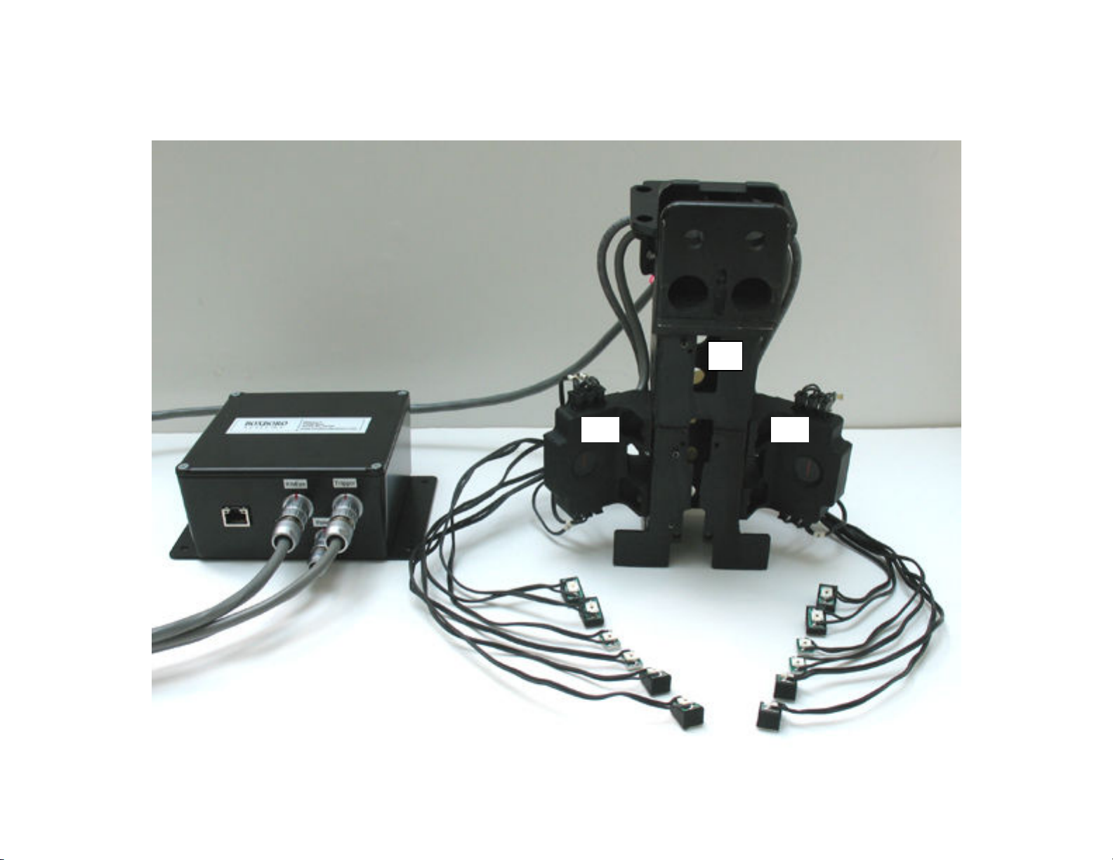
Figure 1. RibEye components
A = LEDs; B = sensor heads; C = LED connector blocks; D = controller; E = s ine; F = interface/trunk box
A A
B
B
C
D
C
F
E

January 2013
7
Figures 2 and 3 show the sensor heads, LED connector blocks, and controller location in greater detail.
The interface/trunk box has sockets for the RibEye controller, power input, and trigger cables
(Figures and 5). Appendix B contains more information on cable assemblies.
Figure 2. Front view of spine
A = sensor heads; B = LED connector blocks
A
A
B
B
B
B
January 2013
8
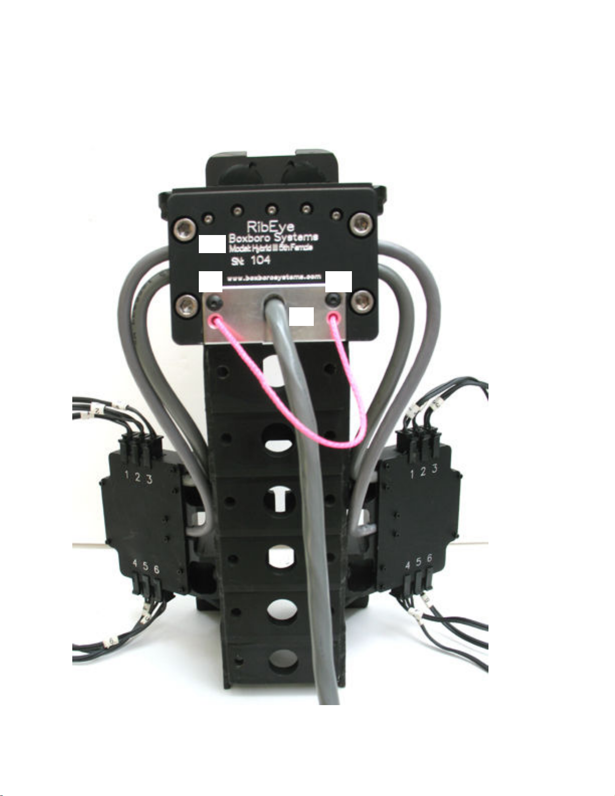
Figure 3. Rear view of spine
A = controller; B = controller mounting screws;
C = RibEye controller connector and cable to trunk box;
D = controller connector screws; E = LED connector blocks
B
B B
B
A
E
E
E
E
D
C
D

January 2013
9
Figure 4. Interface/trunk box
Figure 5. Interface/trunk box wit cables
A = RibEye controller; B = ower; C = trigger
A
B
C

January 2013
10
2.0 Mounting t e RibEye
A diagram for mounting the RibEye controller and sensor heads is shown in Figure 6. The controller and
sensor heads should be mounted to the dummy’s spine before assembling the ribs onto the spine. The
following mounting instructions are specific to the 5
th
Female 2-axis RibEye for the Hybrid III ATD.
January 2013
11
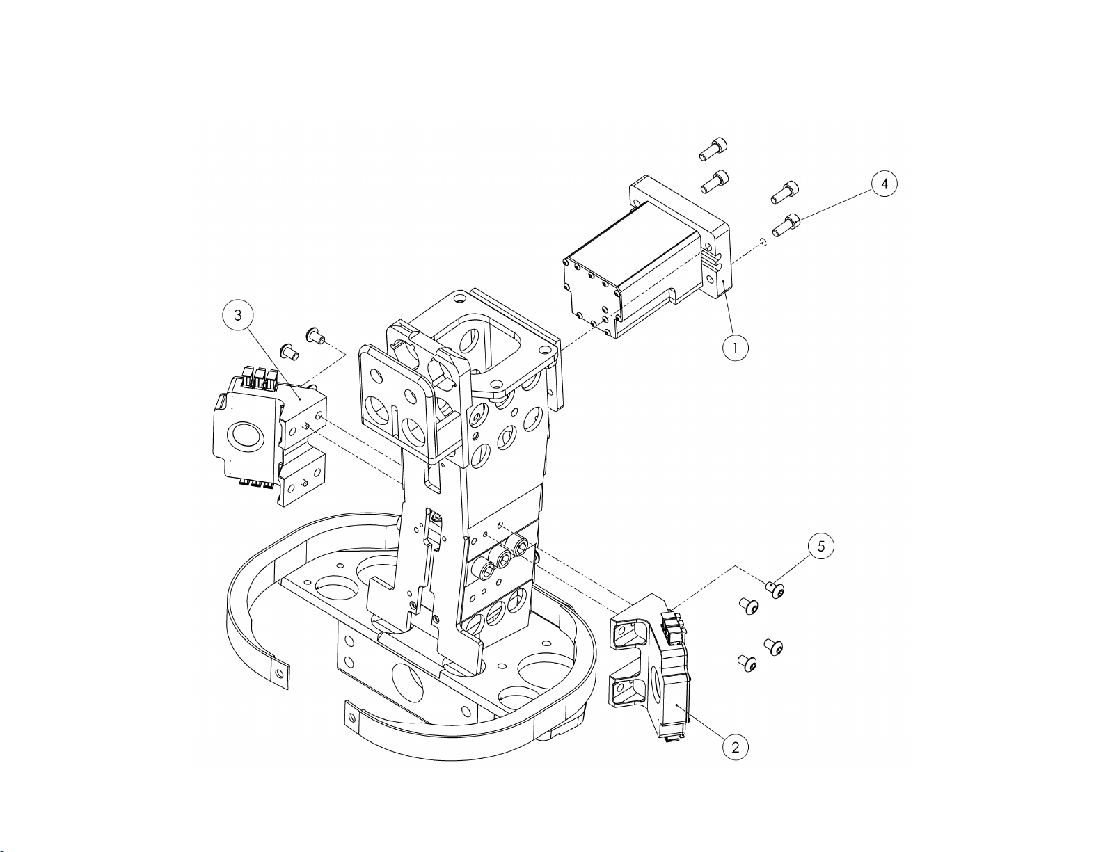
Figure 6. Diagram for mounting RibEye components
1 = controller; 2 = left sensor head; 3 = right sensor head; 4 = four screws for mounting controller (socket head ca #10-32 x 5/8);
5 = six screws for mounting sensor heads (button head ca #10-32 x 1/4)
January 2013
12
2.1 Controller mounting
The controller slides into the back of the spine and is attached with four screws (see Figure 3-B and
Figure 6).
2.2 Installation and removal of t e controller connector and cable
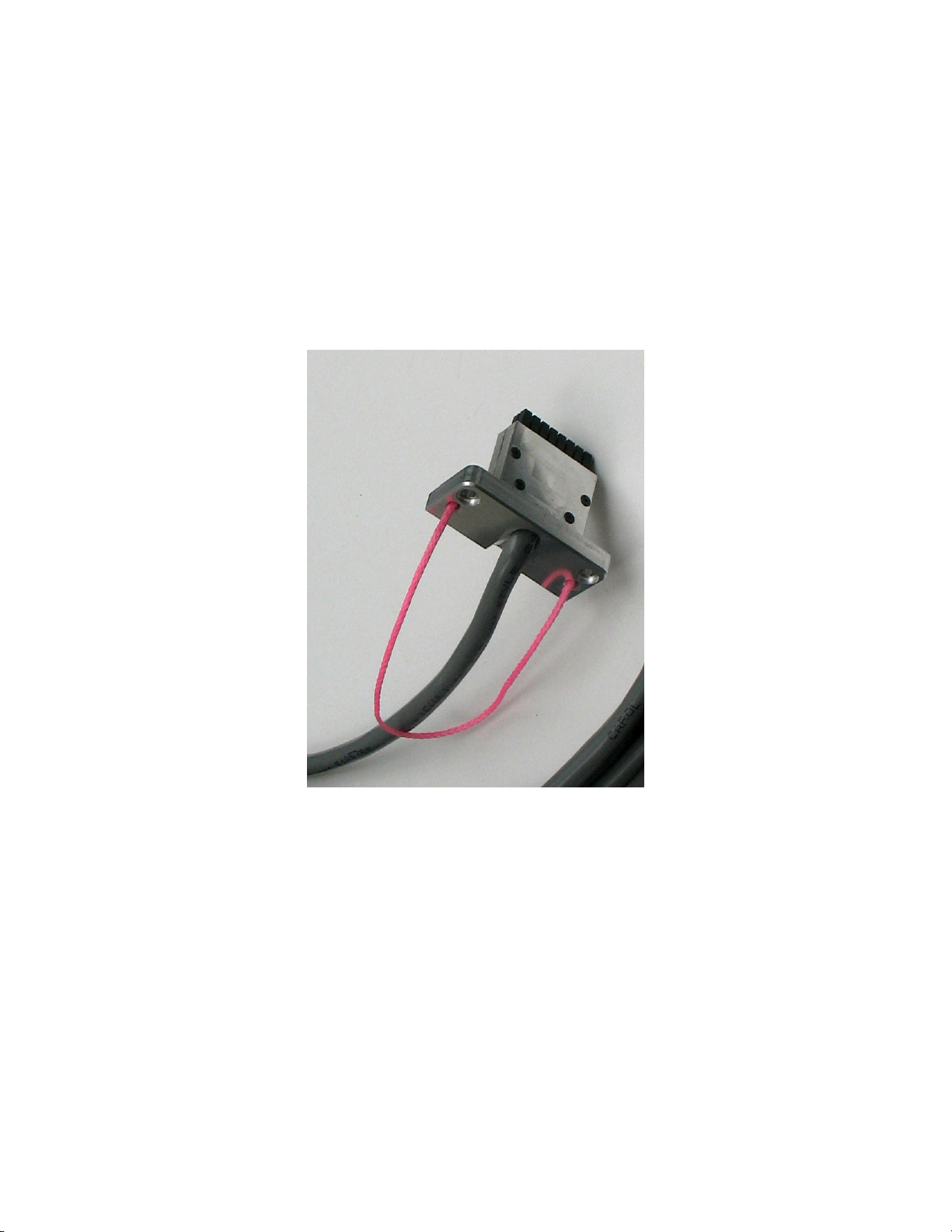
The RibEye controller connector (Figure 7) plugs into the back of the controller and is kept in place by
two # - 0 x 5/8 button-head cap screws (Figure 3-D). The communications cable runs out of the
controller and then down under the dummy skin (jacket) to exit at the bottom of the dummy skin. The
cable is routed to the interface/trunk box.
Figure 7. RibEye controller connector and cable
To install the controller cable, insert the connector into the controller and use an Allen wrench to tighten
the two # - 0 screws, as shown in Figure 8.
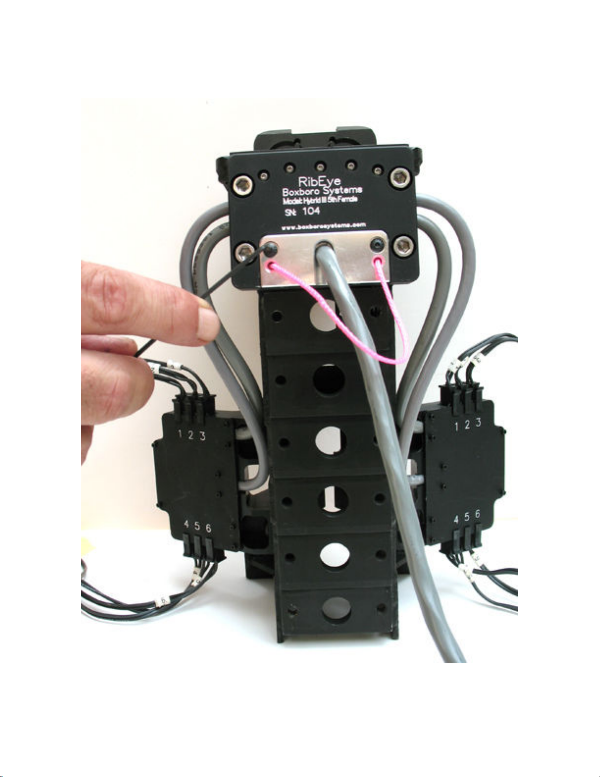
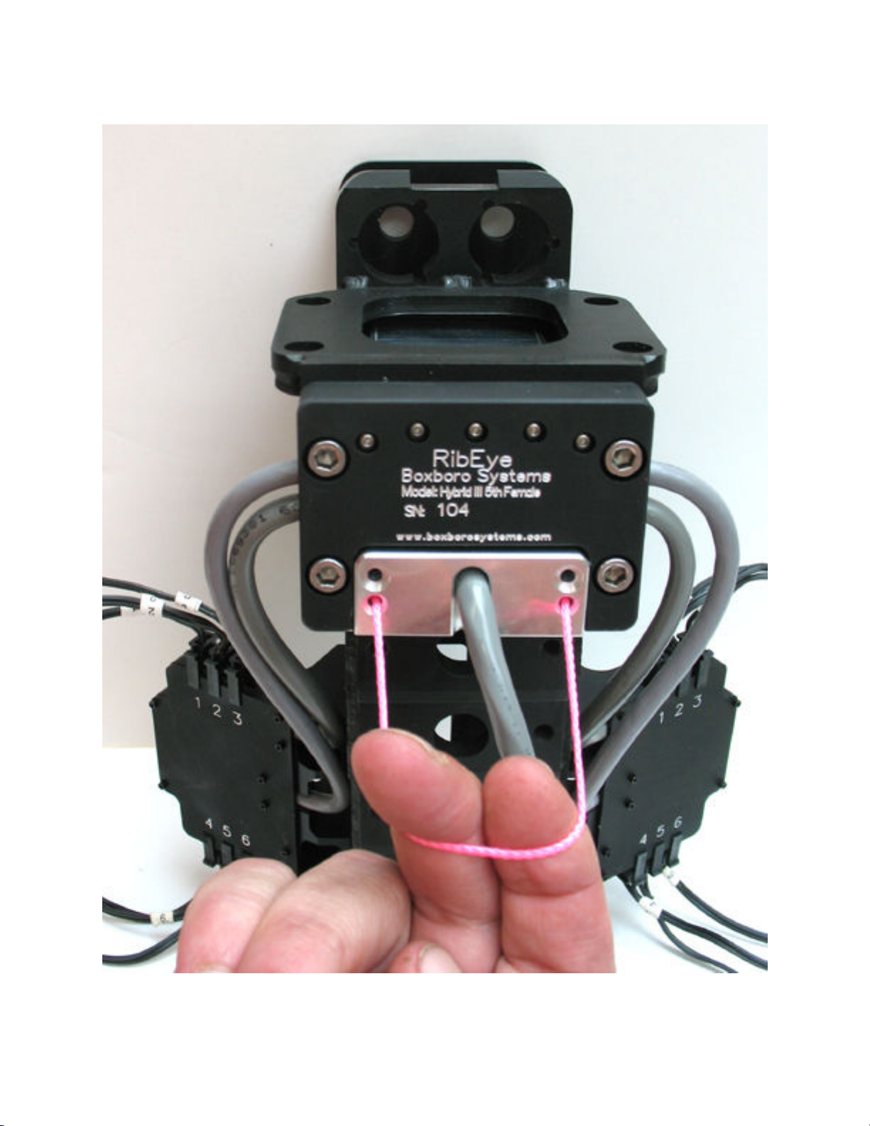
To remove the connector and cable after a test, first remove the screws, then pull on the pink lanyard, as
shown in Figure 9. This will pop the connector out from its mating connection inside the controller.
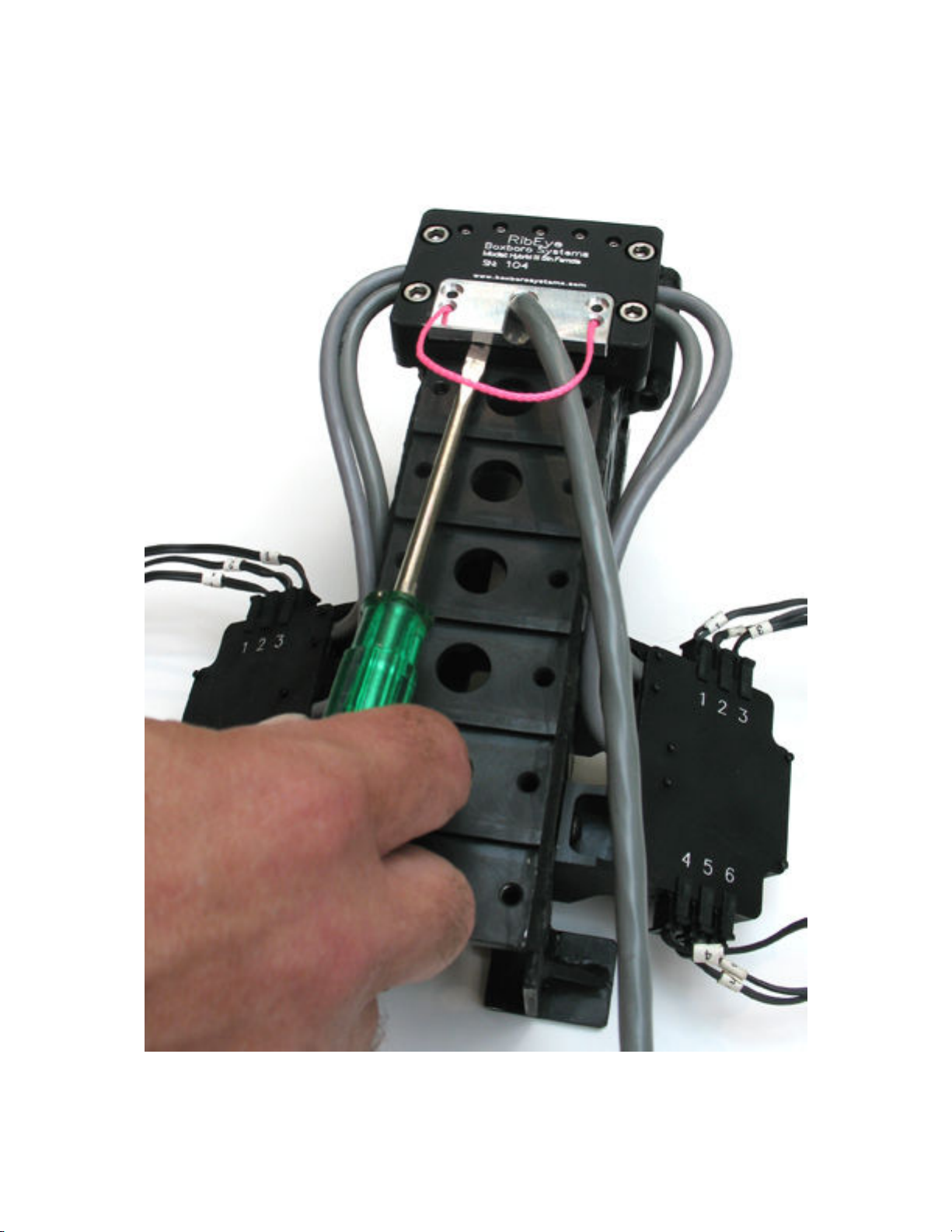
Alternatively, you can use a flat-head screwdriver to pop the connector out. Insert the screwdriver into
the slots on the bottom of the connector as shown in Figure 10. Then twist the screwdriver to lever the
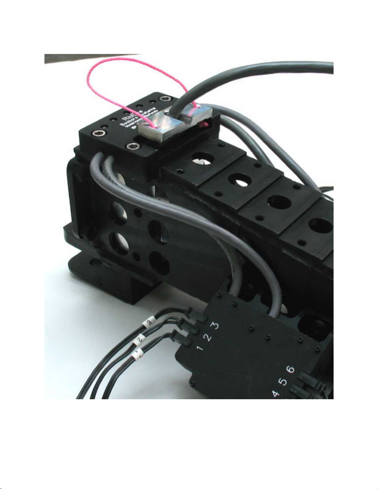
connector out (Figure 11).
After the connector has been popped out, it can be pulled out of the controller safely. DO NOT PULL
ON THE CABLE ITSELF. Figure 12 shows the back of the spine with the controller connector and
cable removed.
January 2013
13
Figure 8. Install or remove screws t at clamp t e connector to t e controller
January 2013
1
Figure 9. Pull t e connector out wit t e lanyard after removing screws
January 2013
15
Figure 10. Pop t e connector from its mate inside t e controller
using a screwdriver to lever t e connector upward
January 2013
16
Figure 11. Connector popped out of t e controller and ready to be removed

January 2013
17
Figure 12. Controller in back of spine after connector and cable ave been removed
January 2013
18
2.3 Sensor ead mounting
The two optical sensor heads are mounted to the left and right sides of the spine. Each sensor head is
attached to the spine with three screws, as shown in Figure 6. Note that the spine has alignment pins that
fit into precision holes in the sensor heads. The sensor heads also contain built-in connector blocks for
the LED cables to plug into. Section 2.5 and Appendix B. provide more details on the LED connector
blocks and cables.
2.4 LED mounting
The LEDs should be mounted to the ribs before the ribs are assembled onto the spine. The top rib is
Rib 1, and the bottom rib is Rib 6. Left and right refer to the dummy’s left and right sides. The LED
cables and connector blocks are marked 1–6 for Ribs 1–6. DANGER: The LEDs are very bright when
driven at full power. Never look directly at the LEDs when they’re turned on.
Angled vs. flat LEDs
Some of the LEDs have an angled mounting surface that aims the LED toward the sensor head to provide
the maximum amount of light to the sensors while minimizing power requirements. The LEDs on Ribs 3
and are installed flat, directly onto the rib surface. The LEDs on Ribs 1, 2, 5, and 6 are mounted on
angled blocks, which are then installed on the rib surface.
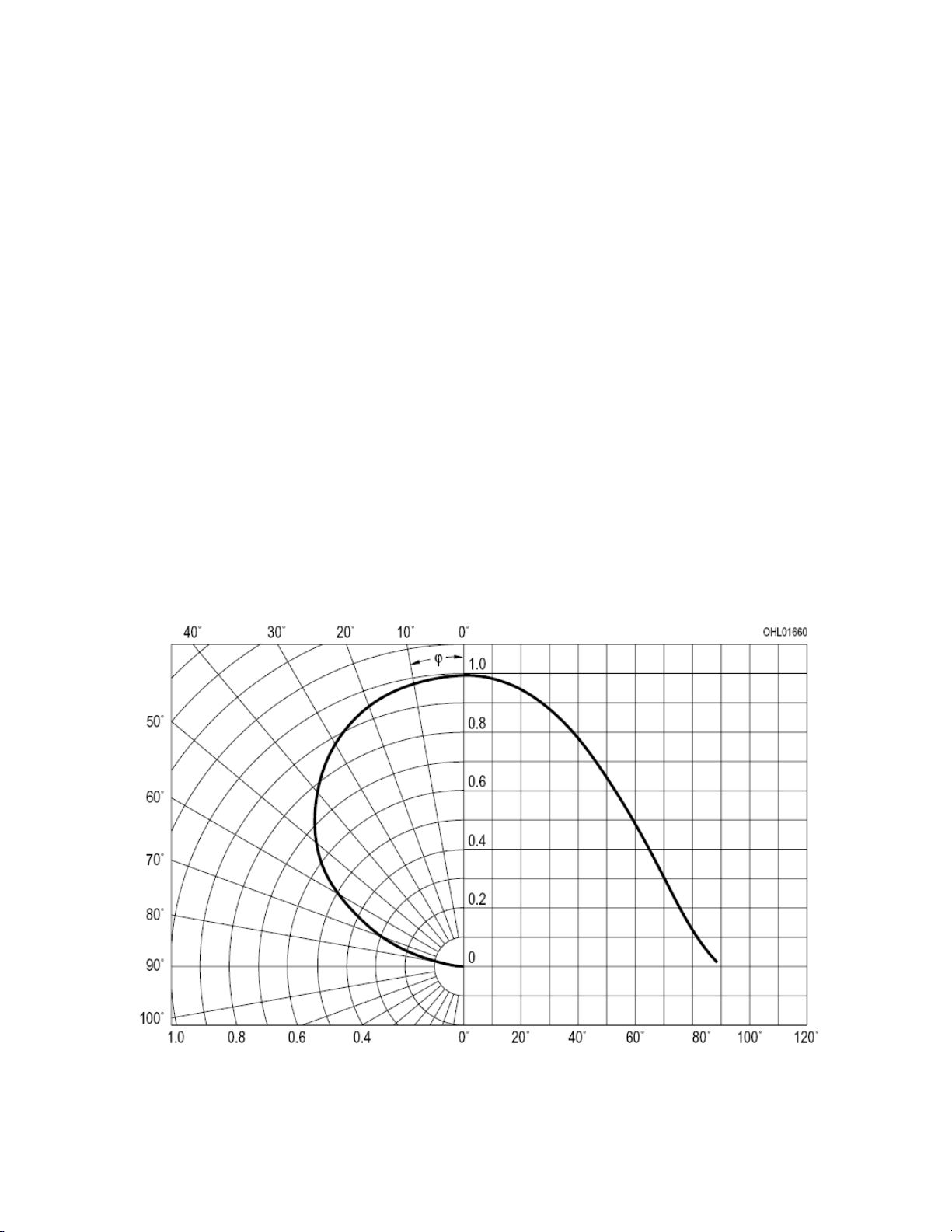
Figure 13 shows the radiation pattern of the LEDs, which explains why angling them improves their
performance. Note that the brightest light is directly in front of the LED (on axis), and the brightness gets
lower at larger angles. The RibEye controller continuously adjusts how hard it drives the LEDs to get a
good signal to the sensors.
Figure 13. LED radiation pattern

January 2013
19
The RibEye uses different calibration curves to process the LED data, depending on which rib that the
LED is mounted on (that is, its Z-axis location up or down). To obtain the guaranteed accuracy, the LEDs
should be plugged into the connectors numbered for the rib they are attached to. The LED on Rib 1 plugs
into connector #1, the LED on Rib 2 plugs into connector #2, etc.
If the light from a LED to a sensor head is blocked, the position reading will be invalid. If the dummy
instrumentation uses a chest potentiometer, the chest pot arm can often block light from the LEDs to the
sensors, causing error codes. If you need to run a test with a chest pot, we recommend that the arm be
painted flat black to minimize reflections. The test operator can also adjust the positions of the LEDs on
the ribs to minimize blockage from a chest pot arm. Please see section .0 below for more information on
error codes.
LED mounting procedure
For best performance, the LEDs should be mounted +/–70 mm in the dummy Y direction from the
centerline of the sternum, or approximately 90 mm along the curve of the ribs from the centerline of the
sternum. This places the LEDs near the tip of the rib, just before the rib thickness increases.
To begin mounting the LEDs, first cut two pieces of double-stick foam tape, each about 8-10 mm long.
Stick the tape to the rib just inside of the thick portion (Figure 1 ). Peel off the paper on the other side,
leaving a sticky surface prepared for the LEDs. Double-stick foam tape is supplied in the RibEye
package.
Figure 14. Rib wit double-stick foam tape in place

January 2013
20
As noted earlier, the LEDs on Ribs 3 and are installed flat, directly onto the rib surface. The LEDs on
Ribs 1, 2, 5, and 6 are mounted on angled blocks, which are then installed on the rib surface. For flat-
mounted LEDs, apply the LED directly to the sticky tape. For angle-mounted LEDs, first snap the LED
into the mounting block (Figures 15 and 16), then apply the block to the sticky tape on the rib. Tightly
secure the LEDs’ lead wires to the ribs using nylon ties. Figures 17 and 18 show flat and angled LEDs
stuck to the ribs.
Figure 15. LED and angled mounting block
Figure 16. LED snapped into angled mounting block
Table of contents
Other Boxboro Measuring Instrument manuals


Popular Measuring Instrument manuals by other brands


Major tech
Major tech MT782 instruction manual

Campbell
Campbell CS225 instruction manual

THORLABS
THORLABS PM10-3 Operation manual

AESSEAL
AESSEAL FLOWTRUE FTP-50-145 Installation, operation & maintenance manual

Amprobe
Amprobe SOLAR-100 user manual

Tanita
Tanita Body Composition Analyzer BF-350 instruction manual


