Boxboro 60005 Instructions for use

January 2022
1
© 2022 Boxboro Systems LLC
HARDWARE USER MANUAL
Second Generation RibEye™ Model #60005
for t e WorldSID 50
t
Male ATD
Boxboro Systems LLC
978-257-2219
www.boxborosystems.com

January 2022
2
© 2022 Boxboro Systems LLC
Table of Contents
Page
1.0 WorldSID RibEye Description ......................................................................................... 6
2.0 RibEye Installation ............................................................................................................ 9
2.1 LED installation on the ribs ..................................................................................... 10
2.1.1 LED assemblies ............................................................................................ 11
2.1.2 Mo nting rearward LEDs on the ribs ........................................................... 18
2.1.3 Mo nting center and forward LEDs on the ribs ........................................... 21
2.1.4 Alternative method for mo nting LEDs on the ribs ..................................... 21
2.2 Installation of ribs and sensor assemblies on the spine ............................................ 22
2.2.1 Installation of sensor bases on spine with mo nting screws ........................ 22
2.2.2 Mo nting sensor front pieces to sensor bases .............................................. 24
2.2.3 Installation of ribs on spine and ro ting LED cables ................................... 26
2.3 Installing components and q ick-testing RibEye operation ..................................... 30
2.3.1 Mo nt the controller feet, battery base, and sho lder inner rib clamp ......... 30
2.3.2 Install the LED breako t cable ..................................................................... 32
2.3.3 Install the controller mo nting plate and controller ..................................... 34
2.3.4 Connect cables to controller and install battery ........................................... 34
2.3.5 Verify operation via q ick test prior to completing ATD assembly ............ 37
2.4 Install mass blocks at bottom of thorax .................................................................... 38
2.5 Install sho lder pads ................................................................................................. 39
3.0 RibEye Operation ............................................................................................................. 40
3.1 Data coordinate system ............................................................................................ 40
3.2 Stat s indicator ......................................................................................................... 41
3.3 Ethernet link and activity lights ............................................................................... 41
3.4 Batteries and charger ................................................................................................ 41
3.5 Error codes ............................................................................................................... 43
4.0 RibEye aintenance ........................................................................................................ 45
4.1 D mmy maintenance for RibEye ............................................................................. 45
Appendixes
A. RibEye specifications .......................................................................................................... 46
A-1. Meas rement acc racy and range ............................................................................ 46
A-2. Power req irements .................................................................................................. 50
A-3. Data acq isition and storage .................................................................................... 50
A-4. Ethernet comm nication .......................................................................................... 50
A-5. Trigger circ its ......................................................................................................... 51
A-6. Armed-o t circ it ..................................................................................................... 51
B. Cable assemblies for connection to vario s DAS Systems ................................................. 57

January 2022
3
© 2022 Boxboro Systems LLC
Table of Contents, continued
Page
C. RibEye cable connector details ........................................................................................... 61
C-1. LED cables ............................................................................................................... 61
C-2. LED breako t cable #70030..................................................................................... 62
C-3. Exit cable connector ................................................................................................. 63
C-4. Sensor cable connector ............................................................................................. 64
List of Figures
Fig re No. Page
1 RibEye sensors mo nted in the d mmy ..................................................................... 6
2 RibEye LEDs mo nted in the d mmy........................................................................ 7
3 RibEye controller with connector end covers in place ............................................... 8
4 Controller sensor connectors ...................................................................................... 8
5 Controller connectors for LED breako t cable, stat s cable, battery cable,
and d mmy exit cable ................................................................................................. 8
6 Battery pack and the adaptor for mo nting the battery pack at the sho lder rib ........ 9
7 LED positions on each rib ......................................................................................... 11
8 LED and angled mo nting block ............................................................................... 12
9 LED snapped into angled mo nting block ................................................................ 12
10 Sho lder center LED adaptor plate, inner rib clamp, pin for sho lder pad,
and wire clamps ......................................................................................................... 13
11 Inner rib clamp plate for thoracic and abdominal ribs............................................... 14
12 Thoracic 1 inner rib clamp plate with LED and wire clamps installed ..................... 14
13 Abdominal 1 inner rib clamp plate with LED and wire clamps installed ................. 15
14 Thoracic 2, thoracic 3, and abdominal 2 inner rib clamp plate
with LEDs and wire clamps installed ........................................................................ 15
15 LED cables #70031 and #70032................................................................................ 16
16 Rearward and forward LED locations ....................................................................... 16
17 LED placement fixt re #70300 ................................................................................. 17
18 Rearward LED placed on do ble-stick tape .............................................................. 18
19 Heat-shrink t bing placed over rearward LED ......................................................... 19
20 Cable ro ting for rearward and center LEDs ............................................................ 20
21 Alternative mo nting of rearward and forward LEDs............................................... 21
22 M5 x 10 flat-head cap screw with precision-machined sho lder .............................. 22
23 Sensor base with label ............................................................................................... 23
24 RibEye sensor bases mo nted to spine ...................................................................... 23
25 RibEye sensor front piece .......................................................................................... 24
26 RibEye sensor label on back and alignment pins ...................................................... 25
27 RibEye sensor assemblies mo nted to spine ............................................................. 26
28 Lower three ribs – abdominal 2, abdominal 1, and thoracic 3 – and
RibEye sensor assemblies mo nted to spine ............................................................. 27
29 Upper three ribs – thoracic 2, thoracic 1, and sho lder – and
RibEye sensor assemblies mo nted to spine ............................................................. 28

January 2022
4
© 2022 Boxboro Systems LLC
List of Figures, continued
Fig re No. Page
30 Right-side impact sensor cable ro ting ..................................................................... 28
31 LED cables exiting the top of ribs abdominal 2 thro gh thoracic 2 and the
bottom of thoracic 1 and abdominal 1 ....................................................................... 29
32 LED ro ted to non-str ck side .................................................................................. 29
33 Controller foot installed on thoracic 1 rib ................................................................. 30
34 Controller foot installed on abdominal 2 rib ............................................................. 31
35 Battery base installed on sho lder rib ....................................................................... 31
36 Sho lder inner rib clamp and sho lder foam pin installed ........................................ 32
37 LED cables pl gged into #70030 breako t cable ...................................................... 32
38 LED breako t cable – view from pelvis with LED cables pl gged in ...................... 33
39 LED breako t cable – view from head with LED cables pl gged in ........................ 33
40 Controller mo nting plate bolted to the controller feet ............................................. 34
41 Controller attached to controller mo nting plate ....................................................... 34
42 Battery box attached to battery mo nt at sho lder .................................................... 35
43 Connector panel at bottom of controller .................................................................... 36
44 Mass blocks #60416 installed at bottom of thorax .................................................... 38
45 Top and bottom views of the sho lder pad assembly ................................................ 39
46 RibEye coordinate system ......................................................................................... 40
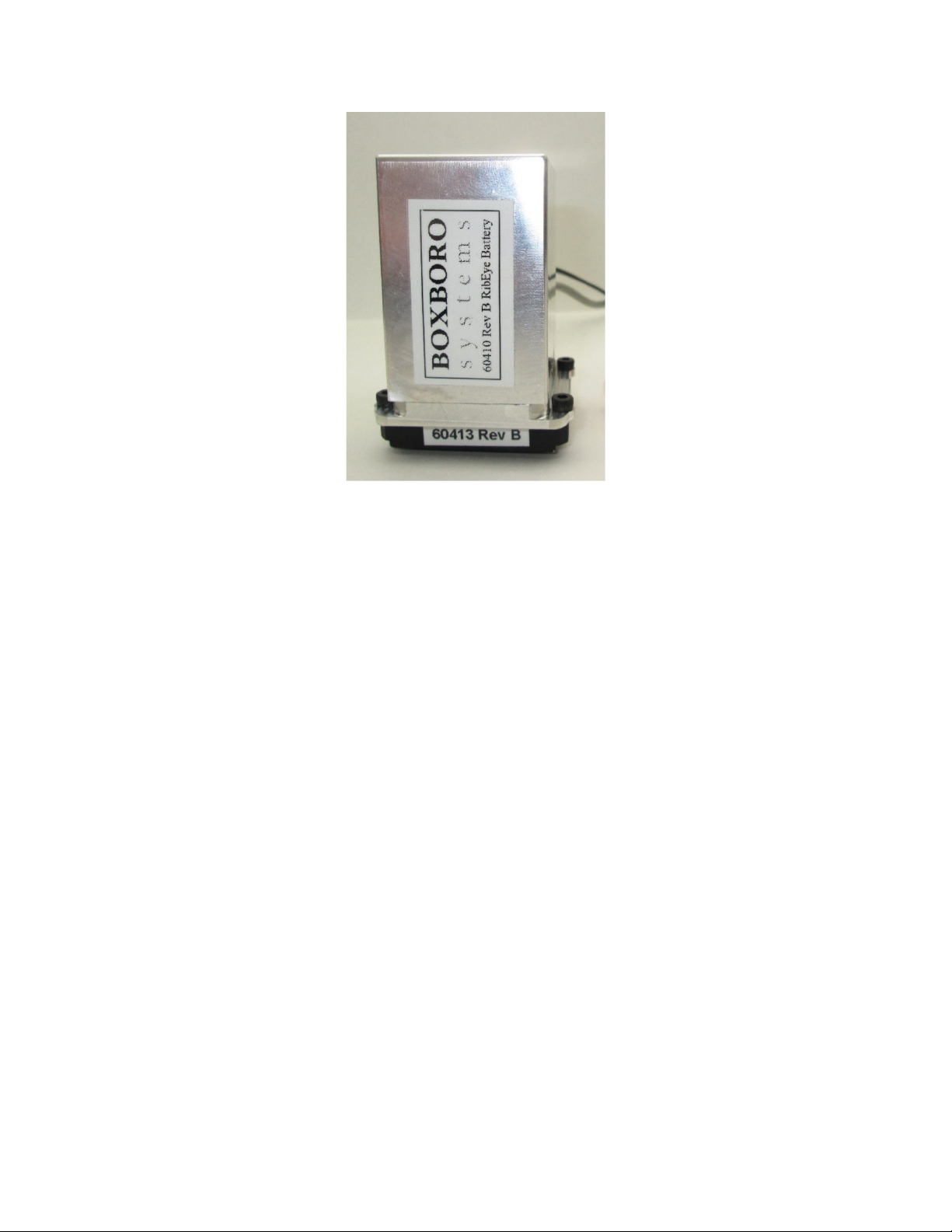
47 Battery pack and adaptor ........................................................................................... 41
48 RibEye battery pack Cell-Con charger and battery cable charger receptacle ........... 42
49 Plot overlay verifying whether LED moved o t of range ......................................... 44
A1 RibEye meas rement range in X-Y plane – all ribs .................................................. 47
A2 RibEye meas rement range in Y-Z plane – pper three ribs .................................... 48
A3 RibEye meas rement range in Y-Z plane – lower three ribs .................................... 49
A4 Trigger inp t circ its ................................................................................................. 52
A5 Trigger inp t config red for DTS MDB-s pplied trigger ......................................... 53
A6 Trigger inp t config red for Kistler NXT32, KiDa , or KiH b ( pper drawing)
or Kistler DTI H b (lower drawing) ......................................................................... 54
A7 Trigger inp t config red for generic pigtail cable assemblies .................................. 55
A8 Trigger switch wiring example for generic pigtail cable assemblies ........................ 55
A9 Armed-o t circ it for generic pigtail cable assemblies ............................................. 56
A10 Example of armed-o t indicator light wiring for generic pigtail cable assemblies ... 56
B1 Cable option for DTS DAS – exit cable #70110 and extension cable #70200 .......... 58
B2 Cable option for Kistler NXT32 DAS – exit cable #70115 ...................................... 58
B3 Cable option for generic DAS with exit and breako t cables – exit cable #70120
and breako t cable #70201 with opto-isolated trigger inp t and armed o tp t ........ 59
B4 Cable option for Kyowa DAS – exit cable #70120 and extension cable #70209 ...... 59
B5 Cable option for Kistler KiH b/KiDa DAS – exit cable #70125 and
extension cable #70208 ............................................................................................. 60
B6 Cable option for Kistler DTI DAS HUB – exit cable #70125 and
extension cable #70218 ............................................................................................. 60

January 2022
5
© 2022 Boxboro Systems LLC
List of Tables
Table No. Page
1 S mmary of LED positions and mo nting methods ................................................. 10
2 Sensor base part n mbers and angles ........................................................................ 22
3 LED flash order on power- p .................................................................................... 31
4 Nominal LED positions ............................................................................................. 31
5 Cell-Con battery charger modes ................................................................................ 42
C1 LED cables #70031 and #70032................................................................................ 61
C2 Breako t cable LED connector (6) ............................................................................ 62
C3 Breako t controller connector ................................................................................... 62
C4 Exit cable controller connector .................................................................................. 63
C5 Sensor cable #70051 .................................................................................................. 64

January 2022
6
© 2022 Boxboro Systems LLC
HARDWARE USER MANUAL
Second Generation RibEye™ Model #60005
for t e WorldSID 50t Male ATD
1.0 WorldSID RibEye Description
The RibEye for the WorldSID anthropomorphic test device (ATD) provides X, Y, and Z position data for
18 light-emitting diodes (LEDs) mo nted on the WorldSID ribs. Three LEDs are mo nted on each of the
six ribs. The RibEye for the WorldSID can be mo nted on either side of the d mmy to meas re left-side
or right-side impacts. Model #60005 is the Second Generation WorldSID RibEye. Appendix A provides
the RibEye meas rement range and other specifications. Up to 3 min tes of data can be collected at a
10-kHz sample rate. Data is stored in non-volatile memory that is retained after power is t rned off. If
external power is lost, the RibEye will operate on its battery. Comm nication to the RibEye is via
Ethernet.
Two sets of three sensors monitor the LED positions, as shown in Fig re 1. The top set of sensors ses
red optical filters and monitors the red LEDs mo nted on the first three ribs: the sho lder rib, thoracic 1
rib, and thoracic 2 rib. The bottom set of sensors ses bl e optical filters and monitors the bl e LEDs
mo nted on the lower three ribs: the thoracic 3 rib, abdominal 1 rib, and abdominal 2 rib.
Figure 1. RibEye sensors mounted in t e dummy
(view from pelvis upward)

January 2022
7
© 2022 Boxboro Systems LLC
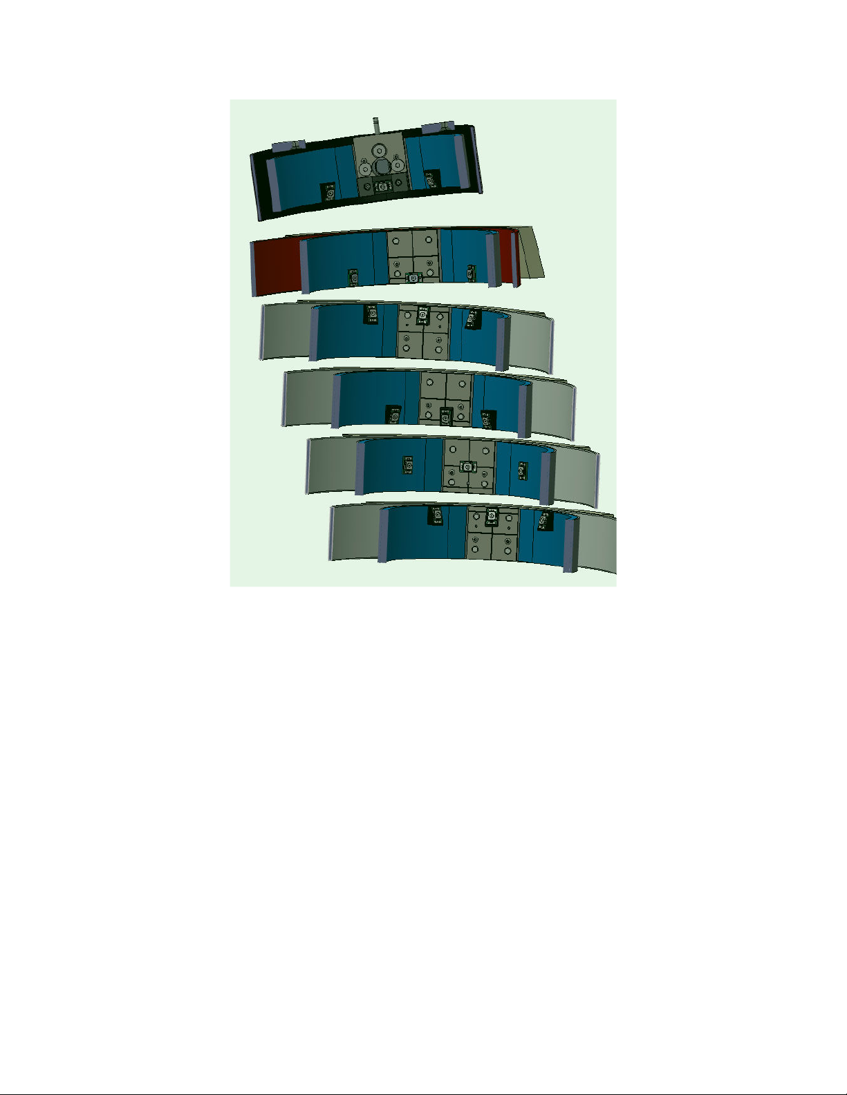
Three RibEye LEDs are mo nted on each rib. Fig re 2 shows the RibEye LEDs installed in the
WorldSID d mmy. The center LEDs are mo nted on the inner rib clamps. The forward LEDs are closer
to the front of the d mmy. The rearward LEDs are closer to the d mmy’s back and are mo nted to the rib
damping material.
Figure 2. RibEye LEDs mounted in t e dummy
(view from pelvis upward)
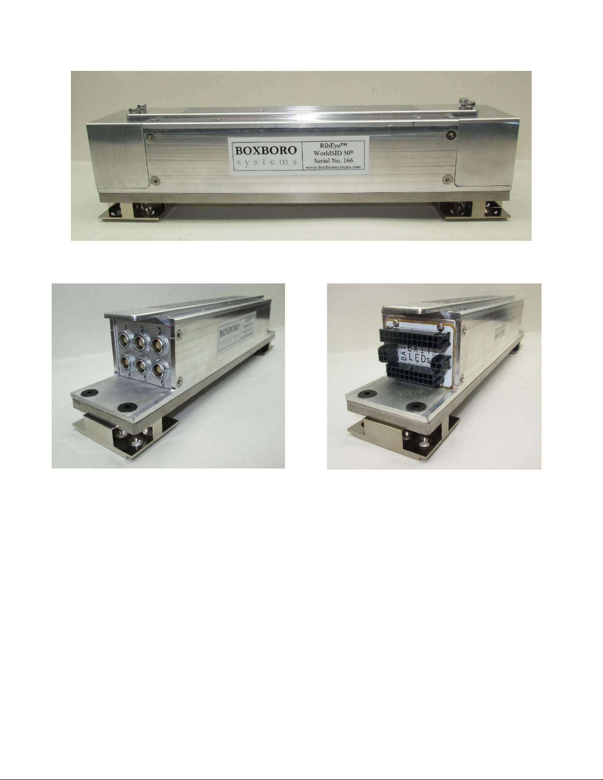
The RibEye controller and battery pack mo nt on the non-str ck side of the d mmy. Fig res 3–6 show
the following views of the controller:
Fig re 3 shows the controller as shipped, with connector covers installed at each end; also shown
are the controller mo nting plate and the controller mo nting feet.
Fig re 4 shows the connectors for the sensors at one end of the controller.
Fig re 5 shows the connectors at the other end of the controller for the LED breako t cable, stat s
cable, battery cable, and d mmy exit cable.
Fig re 6 shows the battery pack and the adaptor for mo nting the battery pack at the sho lder rib.
January 2022
8
© 2022 Boxboro Systems LLC
Figure 3. RibEye controller wit connector end covers in place
Figure 4. Controller sensor connectors
Figure 5. Controller connectors for
LED breakout cable, status cable,
battery cable, and dummy exit cable
January 2022
9
© 2022 Boxboro Systems LLC
Figure 6. Battery pack and t e adaptor
for mounting t e battery pack at t e s oulder rib
2.0 RibEye Installation
This section explains how to mo nt the RibEye components into the WorldSID 50
th
Male ATD. The instr ctions cover
the installation of the LEDs, sensors, controller, battery pack, ballast weights, as well as the cable ro ting. Some
components are mo nted before the ribs are assembled in the d mmy, and others d ring or after rib assembly. Prior to the
RibEye installation the thorax sho ld be disconnected from the Pelvis, and the str ck side ribs sho ld be removed.
Order of assembly
1. Mo nt the LEDs on all of the str ck-side ribs, as described in section 2.1.
2. Install a sensor base on the spine, install the rib, attach the sensor front piece to the base, and ro te the LED cable.
These steps follow a prescribed order starting at the bottom rib (abdominal 2) and working pwards. The sensor bases
are sed to clamp the inner ribs to the spine (sections 2.2.1–2.2.3).
3. Install the controller mo nting feet and the battery mo nt on the non-str ck-side (sections 2.3.1).
4. Install the LED breako t cable, also on the non-str ck side, and connect the six LED cables to the LED breako t cable
(section 2.3.2).
5. Install the controller mo nting plate and controller (section 2.3.3).
6. Connect the cables to the controller and install the battery (section 2.3.4).
7. Power p and test the RibEye before final assembly (section 2.3.5).
8. Attach the thorax to the pelvis with the t ngsten triang lar mass blocks on both sides of the thorax (section 2.4).
9. Install the sho lder pads (section 2.5).
10. Complete d mmy assembly (neck, head, and arms) per the ATD Users Man al

January 2022
10
© 2022 Boxboro Systems LLC
2.1 LED installation on t e ribs
Table 1 s mmarizes the LED positions and mo nting methods for all 18 LEDs. The following sections describe in detail
how to mo nt the LED assemblies onto the ribs. The forward LEDs are closer to the front of the d mmy and the rearward
LEDs are closer to the d mmy’s back, where they are mo nted to the rib damping material. A pict re of the LEDs
mo nted to the ribs is shown in Fig re 7.
Table 1. Summary of LED positions and mounting met ods
Rib
number/type
Rearward LEDs Center LEDs Forward LEDs
Rib #1
(shoulder)
Position Bottom edge of rib
Mounting
Sna LED assembly to
angled block;
Ta e and heat-shrink in
lace
LED assembly already glued to
LED ada tor late;
Screw LED ada tor late to
clam late
Sna LED assembly to
angled block;
Ta e and heat-shrink in
lace
Rib #2
(thoracic 1)
Position Center of rib, mounted flat at bottom edge of the rib
Mounting
Ta e and heat-shrink in
lace
LED assembly already mounted
to clam late
Ta e and heat-shrink in
lace
Rib #3
(thoracic 2)
Position To edge of rib
Mounting
Sna LED assembly to
angled block;
Ta e and heat-shrink in
lace
LED assembly already glued to
angled block;
Screw angled block into clam
late
Sna LED assembly to
angled block;
Ta e and heat-shrink in
lace
Rib #4
(thoracic 3)
Position Bottom edge of rib
Mounting
Sna LED assembly to
angled block;
Ta e and heat-shrink in
lace
LED assembly already glued to
angled block;
Screw angled block into clam
late
Sna LED assembly to
angled block;
Ta e and heat-shrink in
lace
Rib #5
(abdominal 1)
Position Center of rib, mounted flat
Mounting
Ta e and heat-shrink in
lace
LED assembly already mounted
to clam late
Ta e and heat-shrink in
lace
Rib #6
(abdominal 2)
Position To edge of rib
Mounting
Sna LED assembly to
angled block;
Ta e and heat-shrink in
lace
LED assembly already glued to
angled block;
Screw angled block into clam
late
Sna LED assembly to
angled block;
Ta e and heat-shrink in
lace
January 2022
11
© 2022 Boxboro Systems LLC
Figure 7. LED positions on eac rib
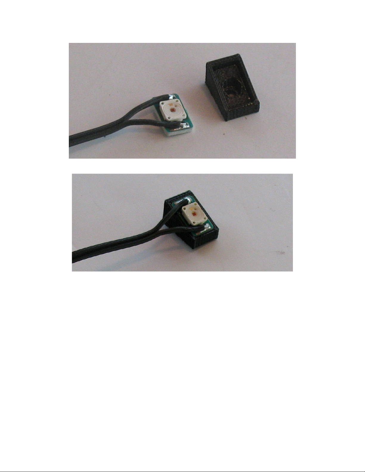
2.1.1 LED assemblies
Fig re 8 shows a LED assembly, with its lead cable attached, and an angled mo nting block. The LED is soldered onto a
metal-clad printed circ it board. Fig re 9 shows the LED assembly snapped into the angled mo nting block. If the LED
does not snap tightly into the angle block, it can be held in place with s per-gl e (cyanoacrylate) or epoxy. The RibEye is
shipped with the LEDs snapped into the blocks. Center LEDs mo nted on angle blocks (thoracic 2-3 and abdominal 1-2)
are epoxied to the angle blocks.
January 2022
12
© 2022 Boxboro Systems LLC
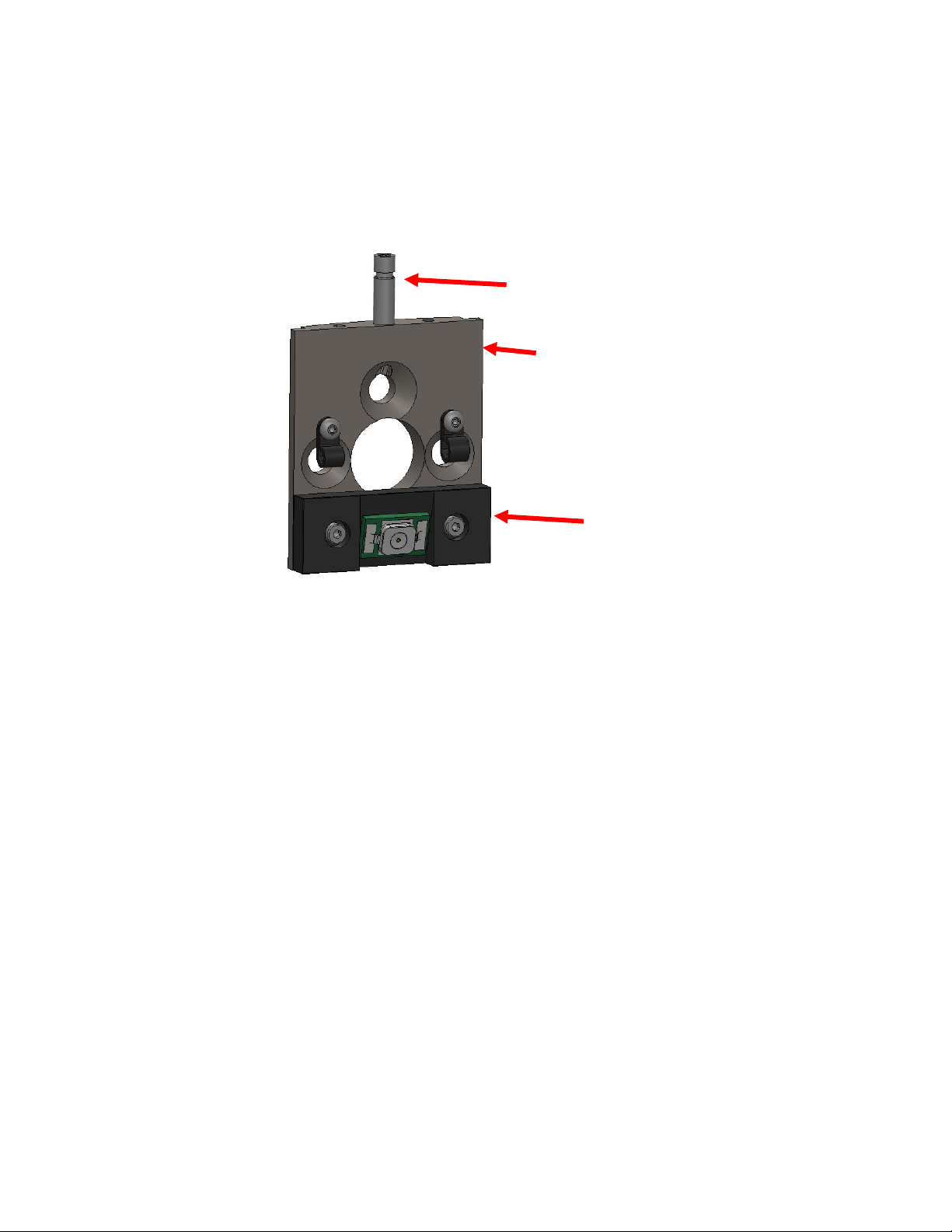
Figure 8. LED and angled mounting block
Figure 9. LED snapped into angled mounting block
The angled mo nting blocks are sed on fo r of the d mmy’s six ribs – the sho lder, thoracic 2, thoracic 3, and
abdominal 2 ribs. On the sho lder and thoracic 3 ribs, the LEDs are mo nted on the bottom edge of the ribs. On the
thoracic 2 and abdominal 2 ribs, the LEDs are mo nted on the top edge of the ribs.
On the d mmy’s other two ribs – the thoracic 1 and abdominal 1 – all three LEDs are mo nted flat, witho t a block.
The thoracic 1 LEDs are mo nted on the bottom edge of the rib, and the abdominal 2 LEDs are mo nted in the center of
the rib.
The center LED on the sho lder rib is epoxied on to a LED adaptor plate (#10089). The adaptor plate is attached to the
sho lder inner rib clamp sing two 2-56 x 1/4 b tton-head cap screws (BHCS).
The sho lder center LED assembly consisting of an inner rib clamp (#10086), LED adaptor plate, and pin for the sho lder
pad (#W50-35047) are shown in Fig re 10. A second inner rib clamp and pin for the sho lder pad are provided for the
non-str ck side.
Also shown in Fig re 10 are two plastic wire clamps that are bolted to the inner rib clamp plate with 2-56 x 1/4 BHCS.
There are two sizes of plastic wire clamps. The smaller wire clamp (0.093-inch diameter) is sized for a single LED cable
and is mo nted on the left side of the inner rib clamp for the cable that goes to the rear LED. The larger wire clamp
(0.125-inch diameter) holds two LED cables and is mo nted on the right side of the rib clamp for the two cables that come
January 2022
13
© 2022 Boxboro Systems LLC
from the controller, past the front LED. The description above is for Left-Side impact, directions are reversed for Right-
Side impact
The cable clamps are from Micro Plastics Inc.:
22CC16A0093-B for the 0.093-inch-diameter clamp
22CC16A0125-B for the 0.125- inch-diameter clamp.
Figure 10. S oulder center LED adaptor plate,
inner rib clamp, pin for s oulder pad, and wire clamps
The center LEDs on the thoracic and abdominal ribs are mo nted to inner rib clamp plates #10085. A CAD drawing of an
inner rib clamp plate is shown in Fig re 11.
Hole A is for installing the angled blocks, which are screwed to the clamp plates sing a 1/4-inch long, 2-56
b tton-head screw that engages in a captive 2-56 n t inside the angled blocks.
The two B holes are for mo nting the nylon wire clamps sing 2-56 x 1/4 BHCS screws.
The scribe lines C are for aligning the LEDs for the thoracic 1 and abdominal LEDs. These LEDs are mo nted to the rib
clamp plate sing 3M VHB tape. The horizontal scribe line at the bottom is for optional mo nting of the thoracic 1 LED
at the bottom of the rib clamp plate.
S oulder inner
rib clamp plate
#10086
LED adaptor plate
#10089
Pin for
S oulder pad
#W50-35047

January 2022
14
© 2022 Boxboro Systems LLC
Figure 11. Inner rib clamp plate for t oracic and abdominal ribs
As noted earlier, the forward LEDs are closer to the front of the d mmy and the rearward LEDs closer to the d mmy’s
back. These rearward and forward LEDs on all ribs are held in place with high-strength do ble-sided foam tape and heat-
shrink t bing. The foam tape is 3M #4952 (1/2-inch wide, VHB acrylic tape). The heat-shrink t bing is 1-1/4 inches in
diameter. The heat-shrink t bing s pplied with the RibEye is made by Q altek, 2:1 shrink ratio, 1-1/4 inches in diameter,
part n mber Q2-Z-1 1/4-01-MS50FT.
Fig re 12 shows the inner rib clamp plate with the LED and wire clamps installed for the thoracic 1 rib. Fig re 13 shows
the inner rib clamp for the abdominal 1 rib. Fig re 14 shows the inner rib clamp plate for the thoracic 2, thoracic 3, and
abdominal 2 ribs. Thoracic 2 and abdominal 2 have the LED and angle block mo nted toward the top of the clamp plate
as shown in Fig re 14. Thoracic 3 has the LED and angle block mo nted to the bottom of the clamp plate—the plate is
rotated 180 degrees for the pict re shown. For the thoracic 2, thoracic 3, and abdominal 2 angle blocks, there is a captive
2-56 n t installed in the angle block, and a 2-56 x1/4 BHCS screw hold the angle block to the inner rib clamp
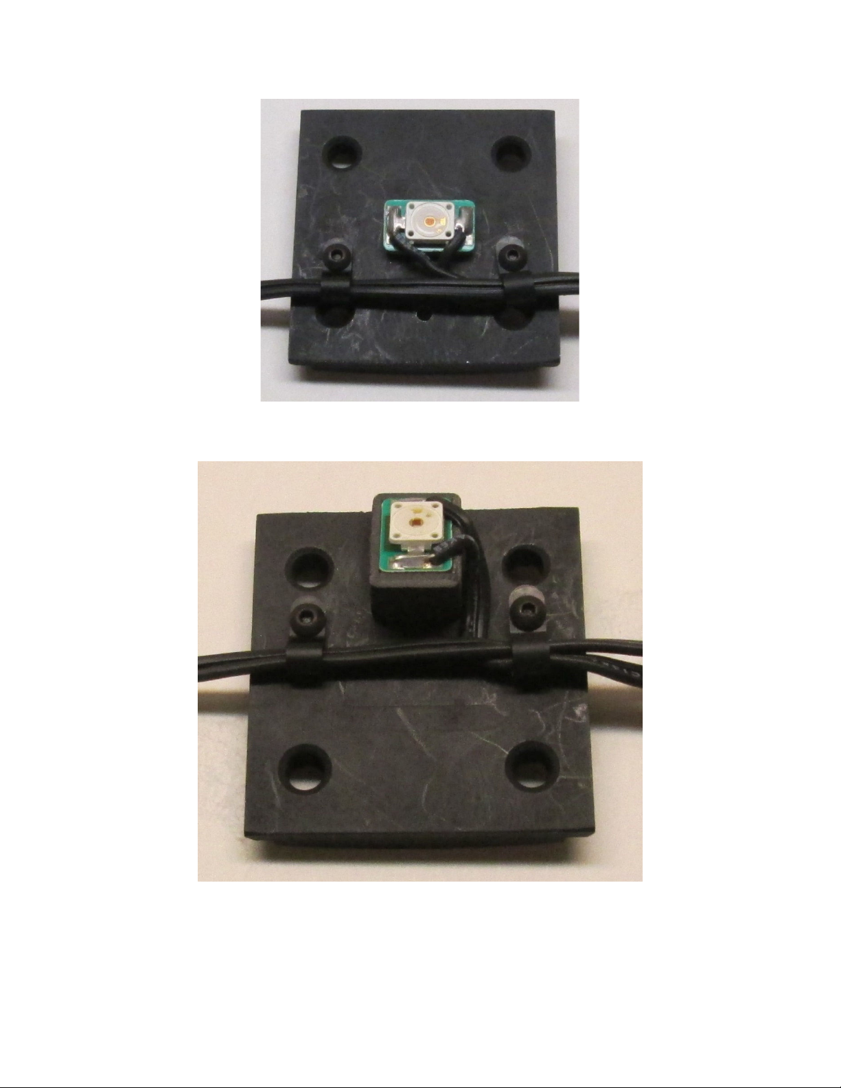
Figure 12. T oracic 1 inner rib clamp plate
wit LED and wire clamps installed
A
B
B
C
C
C
January 2022
15
© 2022 Boxboro Systems LLC
Figure 13. Abdominal 1 inner rib clamp plate
wit LED and wire clamps installed
Figure 14. T oracic 2, t oracic 3, and abdominal 2 inner rib clamp plate
wit LEDs and wire clamps installed
January 2022
16
© 2022 Boxboro Systems LLC
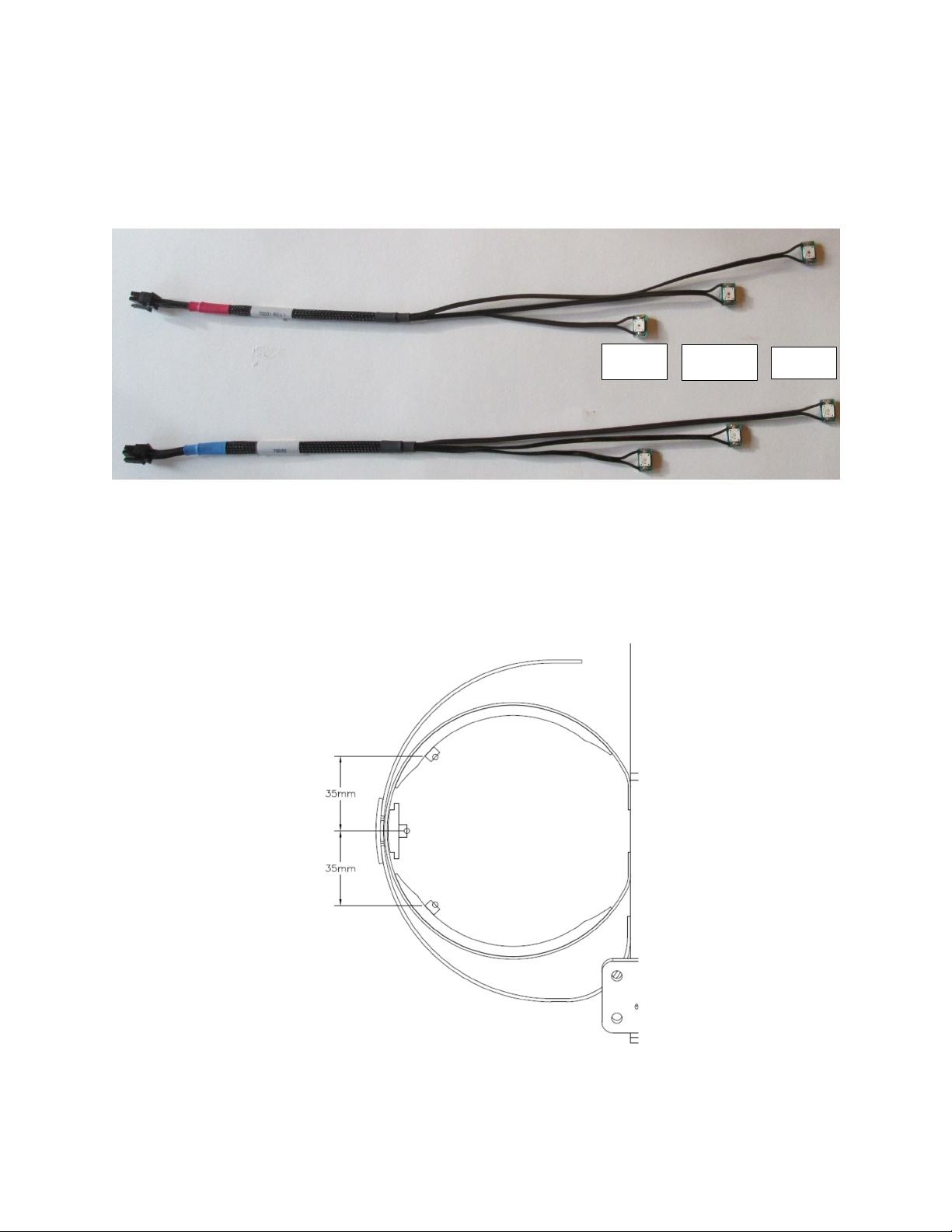
There is one cable for each rib 3-LED set. Cables #70031 are for the pper three ribs and have red heat-shrink t bing near
the connector. Cables #70032 are for the lower 3 ribs and have bl e heat-shrink t bing near the connector. Fig re 15
shows the #70031 and #70032 cables. The LED closest to the connector is mo nted to the front of the rib, the center LED
is mo nted on the inner rib clamp, and the LED farthest from the connector is mo nted on the rear side of the rib.
Figure 15. LED cables #70031 and #70032
The rearward and forward LEDs are typically mo nted 35 mm from the center of the rib as shown in Fig re 16. The
35-mm dimension is the straight-line distance to the edge of the angled block or 1 mm from the edge of the LED metal-
clad printed circ it board.
Figure 16. Rearward and forward LED locations
Front Center
Rear

January 2022
17
© 2022 Boxboro Systems LLC
To simplify the mo nting of the front and rear LEDs, a LED placement fixt re #70300 is available, shown in Fig re 17.
This fixt re holds the rib in place and provides a g ide for placing the VHB tape for the front and rear LEDs. Refer to the
LED placement fixt re instr ctions for sing the fixt re. The instr ctions are available on the RibEye tab of the Boxboro
Systems web site (www.boxborosystems.com).
Figure 17. LED placement fixture #70300
The LEDs m st be mo nted to the ribs before the ribs are installed in the d mmy
On each rib, the rearward LEDs sho ld be mo nted first, then the center LEDs, and finally the forward LEDs. Before
mo nting the LEDs, remove grease and mold-release compo nd by wiping down the mo nting area on the ribs and the
back of the LEDs and mo nting blocks, sing isopropyl alcohol. When installing the foam tape, sq eeze it onto the rib
with at least 15 psi of force. When p tting the LED assembly onto the foam tape, press it on with at least 15 psi of force;
however, do not press on the soft silicone face of the LEDs.
January 2022
18
© 2022 Boxboro Systems LLC
2.1.2 Mounting rearward LEDs on t e ribs
The rearward LEDs sho ld be mo nted according to the following proced re:
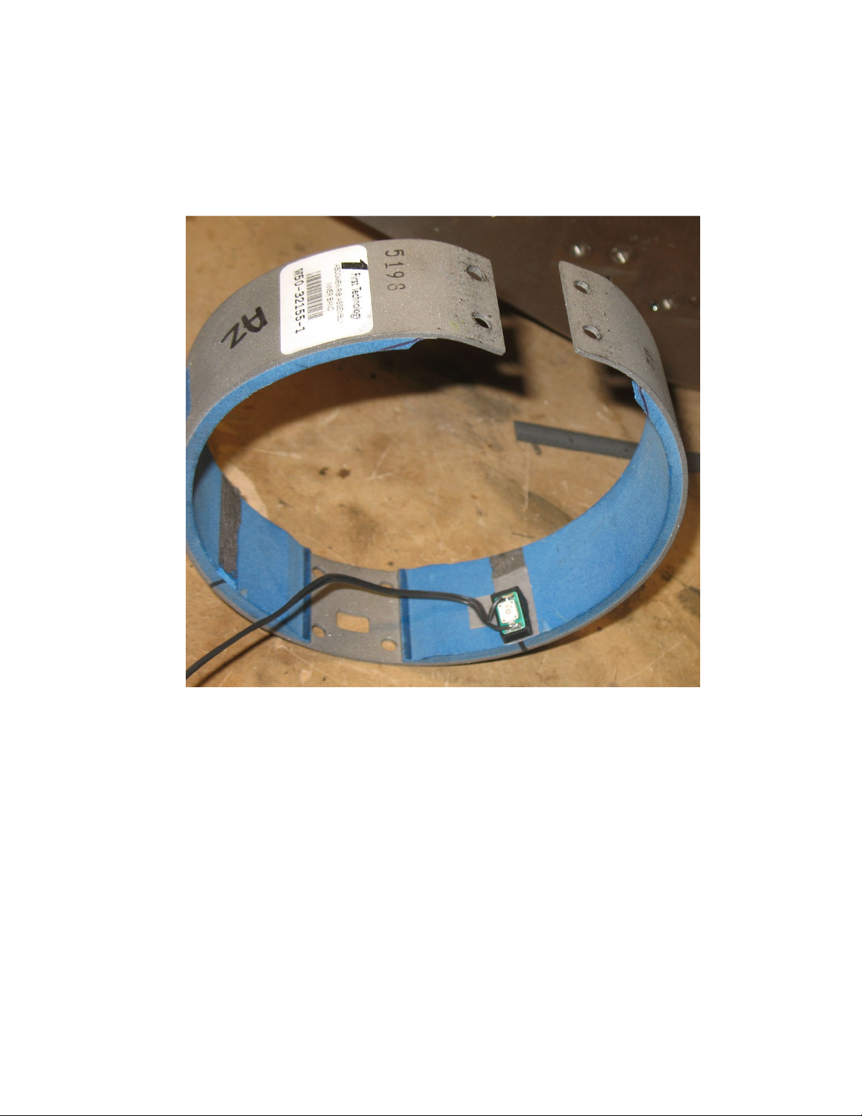
Place a strip of do ble-stick tape on the rib at the rearward LED mo nting location. Add a second piece of tape that will
hold the LED cable in position. Place the LED on the first piece of tape and arrange the cable on the second piece of tape
so that the cable avoids the spot where the center LED will be mo nted (see Fig re 18).
Figure 18. Rearward LED placed on double-stick tape
(with cable arranged to avoid center LED osition)

January 2022
19
© 2022 Boxboro Systems LLC
Heat-shrink “sleeves” are provided with the RibEye (t bing that has been pre-c t and hole-p nched). To make additional
sleeves, c t a piece of heat-shrink t bing 1½ to 2 inches long and p nch a hole in the t bing where the center of the LED
will be (this can be done sing a standard paper hole p nch or similar tool). Slide the t bing sleeve over the rib and LED
as shown in Fig re 19. Center the hole directly over the red or bl e sq are in the center of the LED.
NOTE: Do not use any glue-lined heat-shrink tubing because the glue can
bubble out of the LED hole and cover the LED, blocking its light.
Figure 19. Heat-s rink tubing placed over rearward LED

January 2022
20
© 2022 Boxboro Systems LLC
Caref lly begin shrinking the t bing sing a heat g n while holding the hole over the LED. The heat-shrink
t bing will shrink at temperat res of 70 to 100 degrees C.
Danger
: Some heat guns are very high temperature. Do not burn yourself.
Start heat-shrinking along the o tside of the rib. Then do the inner side of the rib, starting from the edges of the heat-
shrink t bing and working toward the center over the LED. When heat is applied to the hole over the LED, the hole will
expand, exposing the whole white rectang lar body of the LED. Yo might need to stretch the ro nd hole with yo r
finger so that it fits aro nd the rectang lar edge of the LED. Do not to ch the soft silicone face of the LED with sharp
objects. Fig re 20 (right-hand side) shows a rearward LED after the t bing has been shr nk. Make s re that the heat
shrink t bing is tight on the rib and can not rotate and cover the LED.
NOTE: It takes a little practice to master the techniq e of mo nting LEDs with heat-shrink t bing. Yo can always c t
off the t bing and try again.
Figure 20. Cable routing for rearward and center LEDs
Table of contents
Other Boxboro Measuring Instrument manuals


