DualLite UFO-5AW User manual

INSTALLATION INSTRUCTIONS
! IMPORTANT SAFEGUARDS !
WHEN USING ELECTRICAL EQUIPMENT, BASIC SAFETY PRECAUTIONS SHOULD ALWAYS BE
FOLLOWED, INCLUDING THE FOLLOWING:
READ AND FOLLOW ALL SAFETY INSTRUCTIONS
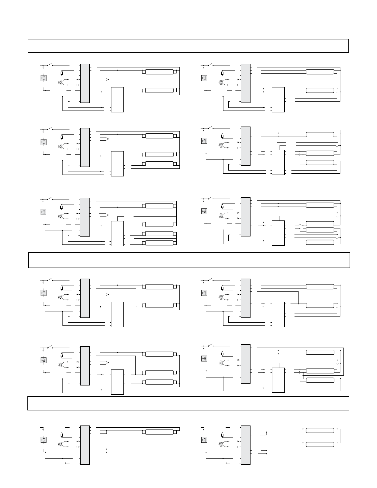
1. To prevent high voltage from being present on red & yellow output leads prior to installation,
inverter connector must be open. Do not join inverter connector until installation is complete and
AC power is supplied to the emergency ballast.
2. This product is for use with most 2’ through 8’ (17 W - 215 W) single pin or bipin fluorescent lamps,
including energy saving, circline, U-shaped and rapid-start (4-pin) long compact fluorescent
lamps.
3. Make sure all connections are in accordance with the National Electrical Code and any local
regulations.
4. To reduce the risk of electric shock, disconnect both normal and emergency power supplies and
inverter connector of the emergency ballast before servicing.
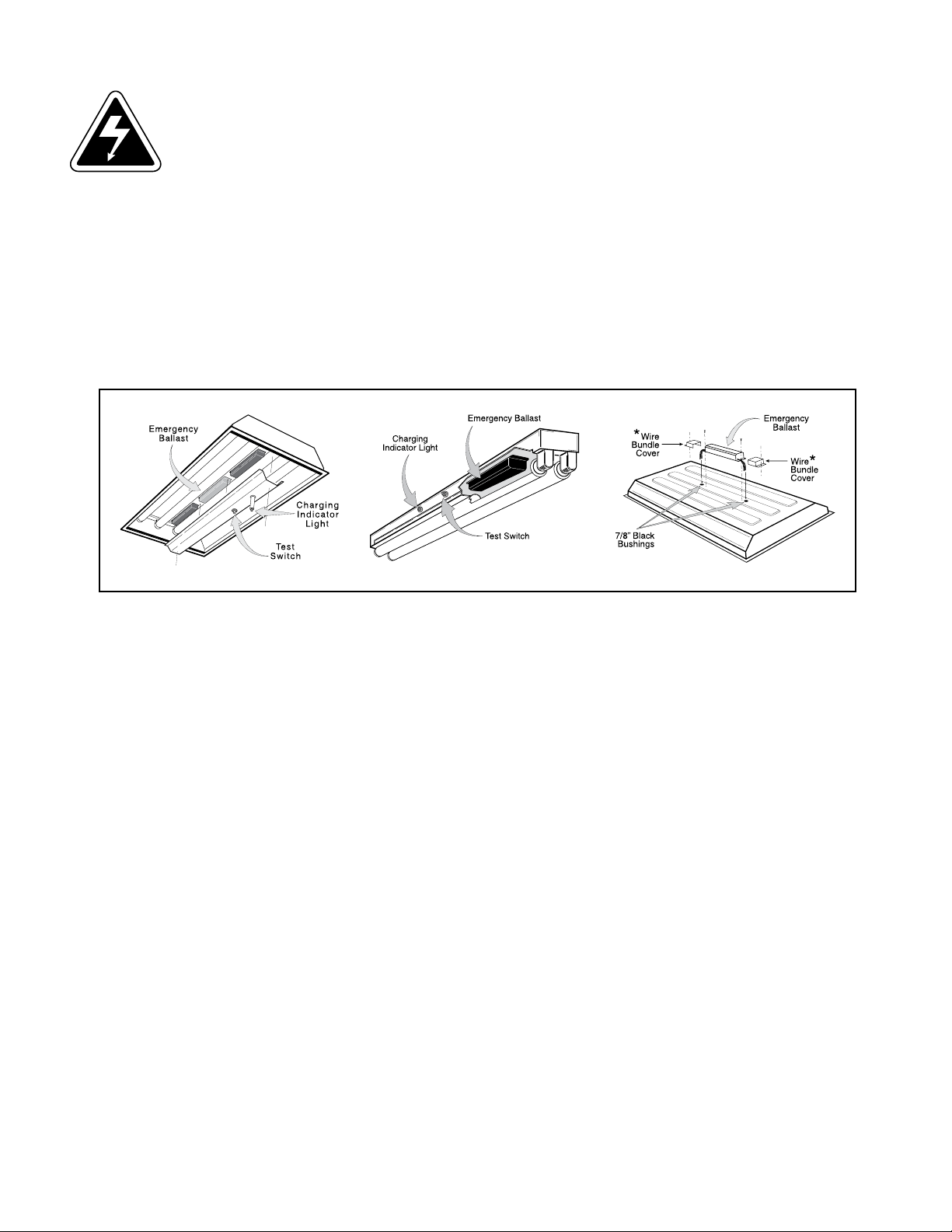
5. This emergency ballast is for factory or field installation in either the ballast channel or on top of
the fixture.
6. This product is suitable for damp locations where the ambient temperature is 0°C minimum,
+50°C maximum. Product is also suitable for installation in sealed and gasketed fixtures. Product
is not suitable for heated air outlets and wet or hazardous locations.
7. An unswitched AC power source is required (120 or 277 VAC, 60 Hz).
8. Do not install near gas or electric heaters.
9. Do not attempt to service the battery. A sealed, no-maintenance battery is used that is not field
replaceable. Contact the manufacturer for information on service.
10. The use of accessory equipment not recommended by the manufacturer may cause an unsafe
condition.
11. Do not use this product for other than intended use.
12. Servicing should be performed by qualified service personnel.
CAUTION: Verify that all replacement lamp types marked on the installed luminaire are also identified
as suitable for use with this inverter/charger pack.
SAVE THESE INSTRUCTIONS
11/26/13
©
Hubbell Lighting, Inc. • 701 Millennium Blvd • Greenville, SC 29607 • (864) 678-1000 • FAX (864) 678-1415 • www.dual-lite.com
443529080531
UFO-5AW
Ni - Cd
CONTAINS NICKEL-CADMIUM
RECHARGEABLE BATTERY.
MUST BE RECYCLED OR
DISPOSED OF PROPERLY.
WARNING – This product contains chemicals known to the State of California to cause cancer, birth defects and/or other
reproductive harm. Thoroughly wash hands after installing, handling, cleaning, or otherwise touching this product.

INSTALLATION
NOTE: Make sure the necessary branch circuit wiring is available. An unswitched source of power is
required. The emergency ballast must be fed from the same branch circuit as the AC ballast.
1. Disconnect AC power from the xture. Remove the ballast channel cover and install the emergency ballast
either in the ballast channel (see Illustrations 1 & 2) or on top of the xture* (see Illustration 3).
2. Select the appropriate wiring diagram to connect the emergency ballast to the AC ballast and lamp. Make sure
all connections are in accordance with the National Electrical Code and any local regulations.
3. Install the test switch through the ballast channel cover of a troffer or through the side of a strip xture. Drill a
1/2" hole and install the switch as shown (see Illustration 1 & 2). Refer to the wiring diagrams section and wire
the test switch so it removes AC power from the unswitched hot line to the emergency ballast.
4. Refer to Illustration 4 and install the charging indicator light so that it will be visible after the xture is installed.
5. In a readily visible location, attach the label “CAUTION–This Unit Has More Than One Power Connection
Point. To Reduce The Risk Of Electric Shock, Disconnect Both The Branch Circuit-Breakers Or Fuses And
Emergency Power Supplies Before Servicing.”
WARNING: TO PREVENT HIGH VOLTAGE FROM BEING PRESENT ON RED AND YELLOW
OUTPUT LEADS PRIOR TO INSTALLATION, INVERTER CONNECTOR MUST BE OPEN. DO
NOT JOIN INVERTER CONNECTOR UNTIL INSTALLATION IS COMPLETE AND AC POWER
IS SUPPLIED TO THE EMERGENCY BALLAST.
2
ILLUSTRATION 2
ILLUSTRATION 1 ILLUSTRATION 3
NOTE: After installing the charging indicator light and test switch, mark each with the appropriate label. If
a detached charging indicator light is used, connect by matching wire colors and install as shown
in Illustration 4.
*For installation on top of the xture, wire bundle covers may be required by state or local codes. These covers are available from the
manufacturer as an accessory kit and must be ordered separately. Call your local distributor or the factory for complete infomation.

6. After installation is complete, supply AC power to the emergency ballast and join the inverter connector.
7. A short-term discharge test may be conducted after the emergency ballast has been charging for one hour.
Charge for 24 hours before conducting a long-term discharge test. Refer to OPERATION.
OPERATION
When AC power is applied, the charging indicator light is illuminated, indicating the battery is being charged. When
power fails, the emergency ballast automatically switches to emergency power, operating one or two lamps at
reduced illumination. When AC power is restored, the emergency ballast returns to the charging mode and delays AC
ballast operation for approximately three seconds to prevent false-tripping of AC ballast (end-of-lamp-life) shutdown
circuits. This emergency ballast will operate the rated lamp load for a minimum of 90 minutes.
MAINTENANCE
Although no routine maintenance is required to keep the emergency ballast functional, it should be checked
periodically to ensure that it is working. The following schedule is recommended:
1. Visually inspect the charging indicator light monthly. It should be illuminated.
2. Test the emergency operation of the xture at 30-day intervals for a minimum of 30 seconds. Either one or two
lamps should operate at reduced illumination.
3. Conduct a 90-minute discharge test once a year. Either one or two lamps should operate at reduced illumination
for at least 90 minutes.
REFER ANY SERVICING INDICATED BY THESE CHECKS TO QUALIFIED PERSONNEL.
ILLUSTRATION 4
NOTE: After installing the charging indicator light and test switch, mark each with the appropriate label.
3
troffer style fixture STRIP STYLE FIXTURE
Charging
Indicator
Light
1/2" White
Bushing
Violet (+)
Brown (–)
Violet (+)
Brown (–)
1/2" White
Bushing
5/8" Black
Bushing
5/8" Black
Bushing
1/2" Punch
Fixture Fixture
Charging
Indicator
Light
* If violet and brown leads are detached, connect to
unit by matching wire colors.

EMERGENCY BALLAST AND AC BALLAST MUST BE FED FROM THE SAME BRANCH CIRCUIT.
TYPICAL SCHEMATICS ONLY. MAY BE USED WITH OTHER BALLASTS. CONSULT THE FACTORY FOR OTHER WIRING DIAGRAMS.
WIRING DIAGRAMS for 1-LAMP emergency operation
4
FIG D THREE (3) LAMP RAPID START BALLAST
FIG B TWO (2) LAMP RAPID START BALLAST
FIG A TWO (2) LAMP INSTANT START BALLAST
FIG C THREE (3) LAMP INSTANT START BALLAST
WIRING DIAGRAMS for 2-LAMP emergency operation (2'-4', 17-40 W lamps only)
FIG G TWO (2) LAMP INSTANT START BALLAST FIG H TWO (2) LAMP RAPID START BALLAST
FIG I THREE (3) LAMP INSTANT START BALLAST FIG J THREE (3) LAMP RAPID START BALLAST
WIRING DIAGRAMS for Emergency-Only fixtures
FIG K ONE (1) 32-215 W LAMP WITHOUT AC BALLAST FIG L TWO (2) 17-40 W LAMPS WITHOUT AC BALLAST
FIG F FOUR (4) LAMP RAPID START BALLAST
FIG E FOUR (4) LAMP INSTANT START BALLAST
WHITE
B
A
L
L
A
S
T
VIOLET
BROWN
WHT/BLK
E
M
E
R
G
E
N
C
Y
RED
WHITE
HOT WHT/RED
CHARGING
INDICATOR
LIGHT
INVERTER
CONNECTOR
BLACK 120V
OR
ORANGE 277V
(CAP UNUSED LEAD)
WALL SWITCH
B
L
K
B
L
K
TEST
SWITCH
COMMON
)
(EMERGENCY
LAMP 1
RED
YEL/BLK
YELLOW
BLUE
2 LAMP
INSTART
START
BALLAST
WHT
BLK
BLUE
RED
BLU/WHT
LAMP 2
BLUE
WHITE
B
A
L
L
A
S
T
VIOLET
BROWN
WHT/BLK
E
M
E
R
G
E
N
C
Y
RED
WHITE
HOT WHT/RED
CHARGING
INDICATOR
LIGHT
INVERTER
CONNECTOR
BLACK 120V
OR
ORANGE 277V
(CAP UNUSED LEAD)
WALL SWITCH
B
L
K
B
L
K
TEST
SWITCH
COMMON
)
(EMERGENCY
LAMP 1
LAMP 2
RED
YEL/BLK
YELLOW
BLU/WHT
BLUE
2 LAMP
RAPID
START
BALLAST
RED
BLUE
WHT
BLK
RED
BLUE
YELLOW
YELLOW
WHITE
B
A
L
L
A
S
T
VIOLET
BROWN
WHT/BLK
E
M
E
R
G
E
N
C
Y
RED
WHITE
HOT WHT/RED
CHARGING
INDICATOR
LIGHT
INVERTER
CONNECTOR
BLACK 120V
OR
ORANGE 277V
(CAP UNUSED LEAD)
WALL SWITCH
B
L
K
B
L
K
TEST
SWITCH
COMMON
)
(EMERGENCY
LAMP 1
LAMP 2
LAMP 3
RED
YEL/BLK
YELLOW
BLUE
3 LAMP
INSTANT
START
BALLAST
WHT
BLK
BLUE
RED
BLU/WHT
BLUE
BLUE
WHITE
B
A
L
L
A
S
T
VIOLET
BROWN
WHT/BLK
E
M
E
R
G
E
N
C
Y
RED
WHITE
HOT WHT/RED
CHARGING
INDICATOR
LIGHT
INVERTER
CONNECTOR
BLACK 120V
OR
ORANGE 277V
(CAP UNUSED LEAD)
WALL SWITCH
B
L
K
B
L
K
TEST
SWITCH
COMMON
RED
)
(EMERGENCY
LAMP 1
LAMP 2
LAMP 3
RED
YEL/BLK
YELLOW
BLU/WHT
BLUE
3 LAMP
RAPID
START
BALLAST
BLUE
WHT
BLK
YELLOW
YELLOW
BLUE
RED
BLU/WHT
BLU/WHT
WHITE
B
A
L
L
A
S
T
VIOLET
BROWN
WHT/BLK
E
M
E
R
G
E
N
C
Y
RED
WHITE
HOT WHT/RED
CHARGING
INDICATOR
LIGHT
INVERTER
CONNECTOR
BLACK 120V
OR
ORANGE 277V
(CAP UNUSED LEAD)
WALL SWITCH
B
L
K
B
L
K
TEST
SWITCH
COMMON
)
(EMERGENCY
LAMP 1
LAMP 4
LAMP 2
LAMP 3
RED
YEL/BLK
YELLOW
BLUE
4 LAMP
INSTANT
START
BALLAST
WHT
BLK
BLUE
YELLOW
BLU/WHT
BLUE
RED
YELLOW
RED
WHITE
B
A
L
L
A
S
T
VIOLET
BROWN
WHT/BLK
E
M
E
R
G
E
N
C
Y
RED
WHITE
HOT WHT/RED
CHARGING
INDICATOR
LIGHT
INVERTER
CONNECTOR
BLACK 120V
OR
ORANGE 277V
(CAP UNUSED LEAD)
WALL SWITCH
B
L
K
B
L
K
TEST
SWITCH
COMMON
)
(EMERGENCY
LAMP 1
LAMP 4
LAMP 2
LAMP 3
RED
YEL/BLK
YELLOW
BLU/WHT
BLUE
4 LAMP
RAPID
START
BALLAST
RED
WHT
BLK
YELLOW
YELLOW
RED
BROWN
BLUE
BLU/WHT
BROWN
BLUE
BLU/WHT
WHITE
B
A
L
L
A
S
T
VIOLET
BROWN
WHT/BLK
E
M
E
R
G
E
N
C
Y
RED
WHITE
HOT WHT/RED
CHARGING
INDICATOR
LIGHT
INVERTER
CONNECTOR
BLACK 120V
OR
ORANGE 277V
(CAP UNUSED LEAD)
WALL SWITCH
B
L
K
B
L
K
TEST
SWITCH
COMMON
LAMP 1
RED
YEL/BLK
YELLOW
BLUE
2 LAMP
INSTART
START
BALLAST
WHT
BLK
BLUE
RED
BLU/WHT
LAMP 2
BLUE
WHITE
B
A
L
L
A
S
T
VIOLET
BROWN
WHT/BLK
E
M
E
R
G
E
N
C
Y
RED
WHITE
HOT WHT/RED
CHARGING
INDICATOR
LIGHT
INVERTER
CONNECTOR
BLACK 120V
OR
ORANGE 277V
(CAP UNUSED LEAD)
WALL SWITCH
B
L
K
B
L
K
TEST
SWITCH
COMMON
LAMP 1
LAMP 2
RED
YEL/BLK
YELLOW
BLU/WHT
BLUE
2 LAMP
RAPID
START
BALLAST
RED
BLUE
WHT
BLK
RED
BLUE
YELLOW
YELLOW
WHITE
B
A
L
L
A
S
T
VIOLET
BROWN
WHT/BLK
E
M
E
R
G
E
N
C
Y
RED
WHITE
HOT WHT/RED
CHARGING
INDICATOR
LIGHT
INVERTER
CONNECTOR
BLACK 120V
OR
ORANGE 277V
(CAP UNUSED LEAD)
WALL SWITCH
B
L
K
B
L
K
TEST
SWITCH
COMMON
)
(EMERGENCY
LAMP 1
LAMP 2
LAMP 3
RED
YEL/BLK
YELLOW
BLUE
3 LAMP
INSTANT
START
BALLAST
WHT
BLK
BLUE
RED
BLU/WHT
BLUE
BLUE
)
(EMERGENCY
WHITE
B
A
L
L
A
S
T
VIOLET
BROWN
WHT/BLK
E
M
E
R
G
E
N
C
Y
RED
WHITE
HOT WHT/RED
CHARGING
INDICATOR
LIGHT
INVERTER
CONNECTOR
BLACK 120V
OR
ORANGE 277V
(CAP UNUSED LEAD)
WALL SWITCH
B
L
K
B
L
K
TEST
SWITCH
COMMON
RED
)
(EMERGENCY
LAMP 1
LAMP 2
LAMP 3
RED
YEL/BLK
YELLOW
BLU/WHT
BLUE
3 LAMP
RAPID
START
BALLAST
BLUE
WHT
BLK
YELLOW
YELLOW
BLUE
RED
BLU/WHT
BLU/WHT
)
(EMERGENCY
LAMP
RED
YEL/BLK
YELLOW
BLU/WHT
BLUE
CAP
CAP
CAP
WHITE
B
A
L
L
A
S
T
VIOLET
BROWN
WHT/BLK
E
M
E
R
G
E
N
C
Y
RED
WHITE
HOT WHT/RED
CHARGING
INDICATOR
LIGHT
INVERTER
CONNECTOR
BLACK 120V
OR
ORANGE 277V
(CAP UNUSED LEAD)
B
L
K
B
L
K
TEST
SWITCH
COMMON
CAP
LAMP
RED
YEL/BLK
YELLOW
BLU/WHT
BLUE
CAP
CAP
LAMP
CAP
WHITE
B
A
L
L
A
S
T
VIOLET
BROWN
WHT/BLK
E
M
E
R
G
E
N
C
Y
RED
WHITE
HOT WHT/RED
CHARGING
INDICATOR
LIGHT
INVERTER
CONNECTOR
BLACK 120V
OR
ORANGE 277V
(CAP UNUSED LEAD)
B
L
K
B
L
K
TEST
SWITCH
COMMON
CAP
Other DualLite Batteries Pack manuals
Popular Batteries Pack manuals by other brands

Inventus Power
Inventus Power PROTRXion M-24V60-TRX quick start guide

MRHANDSFREE
MRHANDSFREE Portable Power Charger Pure Edition user manual

Tripp Lite
Tripp Lite External Battery Pack BP240V557C-1PH specification

PowerWalker
PowerWalker LiFe Battery System 48-100 manual

Silvercrest
Silvercrest 279396 operating instructions

Tripp Lite
Tripp Lite BP Series owner's manual

Tripp Lite
Tripp Lite BP48V60-3UNAFTA Specifications

PowerWalker
PowerWalker BP S48T-12x9Ah user manual

Tripp Lite
Tripp Lite BP480V55 Specification sheet

nedis
nedis UPBK65W30000BK quick start guide

Deka
Deka fahrenheit Installation and operating instructions

dji
dji MAVIC 3 BWX260-5000-15.4 Product information