manuals.online logo
Brands
  1. Home
  2. •
  3. Brands
  4. •
  5. B+B SmartWorx
  6. •
  7. Server
  8. •
  9. B+B SmartWorx VESR424D User manual

B+B SmartWorx VESR424D User manual

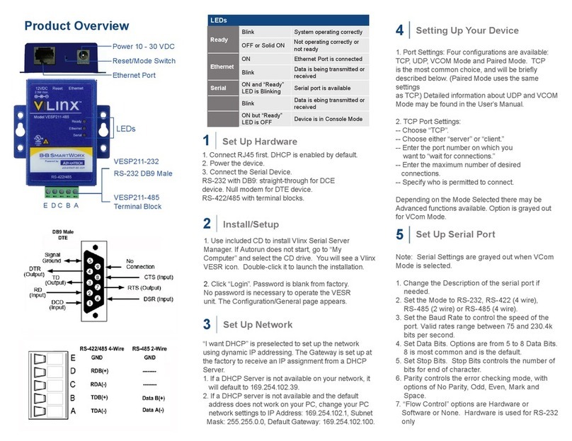
Serial Port Pinout - Terminal Block (# VESR424D)
Terminal RS-232 RS-422 RS-485
ARTS TDA (-) Data A (-)
B TD TDB (+) Data B (+)
C CTS RDA (-) ---
D RD RDB (+) ---
E GND GND GND
Documentation N umber: 710-11137-00_r1_VESR424x_1918qsg
1 (888) 948-2248 | Europe: +353 91 792444
707 Dayton Road | PO Box 1040 | Ottawa, IL 61350
Phone: (815) 433-5100 | Fax: (815) 433-5109
www.advantech-bb.com | E-mail: support@advantech-bb.com
Before you begin, be
sure you have the following:
Model VESR424D or VESR424T
Ethernet Serial Server
Fast and easy on the web:
www.advantech-bb.com
+ VESR424D or VESR424T
+ CD with Software & Manual
+ DIN Rail & Panel Mount Brackets
QUICK START
GUIDE
Serial Port Pinout - DB9 (# VESR424T)
Terminal RS-232 RS-422/RS-485
4-Wire
RS485
2-Wire
1 DCD RDA (-) ---
2 RD RDB (+) ---
3 TD TDB (+) Data B (+)
4 DTR TDA (-) Data A (-)
5 GND GND GND
6 DSR --- ---
7RTS --- ---
8 CTS --- ---
9 --- --- ---
VESR424D
VESR424T
SUITABLE FOR USE IN CLASS I, DIVISION 2, GROUPS A, B,
C AND D HAZARDOUS LOCATIONS, OR NONHAZARDOUS
LOCATIONS ONLY.
CONVENANT À L’EMPLOI DANS LES SITES DANGEREUX
DE CLASSE I, DIVISION 2, GROUPES A, B, C ET D, OU
DANS LES SITES NON HASARDEUX SEULEMENT
UL Class 1 / Division 2
5
WARNING - EXPLOSION HAZARD - SUBSTITUTION OF ANY
COMPONENT MAY IMPAIR SUITABILITY FOR CLASS I, DIVISION 2.
ATTENTION - DANGER D’EXPLOSION - LA SUBSTITUTION DE
COMPOSANTS PEUT ENTRAÎNER UNE ADÉQUATION À LA
CLASSE I, DIVISION 2.
The unit is to be powered by a Class 2 power source, of a grounded-
type, when power is applied to the barrel connector.
L’unité doit être alimentée par une source d’alimentation de classe 2, de
type mise à la terre, lorsque le connecteur du canon est alimenté.
THE POWER CABLE MUST HAVE A MINIMUM RATING OF 80 °C.
LE CÂBLE D’ALIMENTATION DOIT AVOIR UNE INDICATION
MINIMALE DE 80 °C.
Power cannot be applied to both the terminal block and barrel
connectors simultaneously.
L’alimentation ne peut pas être appliquée simultanément aux
connecteurs du bornier et du barillet.
The use of coaxial cable for the eld wiring shall be in accordance with
Class 2/Class 3 requirements in Article 725 of the NEC.
L’utilisation d’un câble coaxial pour le câblage sur site doit être conforme
aux exigences de classe 2 / classe 3 de l’article 725 du NEC.
One Conductor Per Terminal
Un conducteur par borne
Use Copper Wire Only
Utiliser uniquement du l de cuivre
Wire Size: 28 to 16 AWG
Taille de l: 28 à 16 AWG
Tightening Torque: 5 KG-CM
Couple de serrage: 5 KG-CM
Wire Temperature Rating: 105 °C Minimum (Sized for 60 °C Ampacity)
Indice de température du l: 105 °C Minimum (calibré pour 60 °C)
80 °C Maximum Surrounding Ambient Air Temperature
80 °C Température ambiante ambiante maximale
Install/Connect the Hardware
Install/Run Vlinx Manager
Congure the Serial Server Test and Verify Operation
1
2
3 4
Unpack the serial server from the shipping container.
Verify that all included items are present:
• Vlinx™VESR4x4 serial server module
• CD with Vlinx Manager software and user
manual
• (2) panel mount adapters and (4) mounting
screws
• DIN rail mount adapter and (3) mounting
screws.
• This quick start guide
General Setup
• Enter a name for the serial server. This name will
show up in the serial server list in Vlinx Manager.
• Change the login password, if desired.
Enter The Network Settings
• The serial server is congured at the factory to get
an IP address automatically (DHCP). If a DHCP
server is not available on your network, it will default
to 169.254.102.39.
• If a static IP is desired, uncheck the box, “I want
DHCP to setup the network”. Enter the static IP,
Subnet Mask, and Default Gateway information.
Setup the Serial Port Communications
• For each serial port on the device, select the
communications mode: RS-232, RS-422, RS-485
(2-wire), RS-485 (4-wire) .
• Select the communications parameters (Baud Rate,
Data Bits, Stop Bits, Parity and Flow Control) for
your serial device.
Setup the Serial Port Network Protocol
• Select the type of network protocol you want to use
for each port: TCP, UDP, VCOM or Paired Mode.
• TCP: select whether the serial server will operate
as a Client or Server, then congure the required
IP address, port numbers and other related
parameters.
• UDP: congure the IP addresses, ports and other
related parameters for the devices that you want to
receive data from and send data to.
• VCOM: congure the serial port to act as a virtual
COM port on the PC. You must also add the VCOM
driver to the PC using the “Add” button in Vlinx
Manager.
• Paired Mode: congure the serial server to be
paired with another serial server. Congure it as
either the client or the server in the pair and set up
the IP address, port numbers, etc.
• Set up Advanced Parameters, as necessary, for
your application. Click on the “Advanced” button
to set up serial and network timers and packet
delimiters.
Save your conguration to the serial server
• The device will re-boot after saving the settings.
• Set up serial server as a TCP Server on serial
port 1.
• Set serial port to RS-232 on serial port 1.
• Set to 9600 8-N-1 on serial port 1.
• Loopback serial port 1 by connecting TD to
RD.
• Open a command window and type “telnet
x.x.x.xyyyy” where x.x.x.x is the IP address of
the serial server and yyyy is the port number
of the serial port.
• Type characters on the keyboard. The
characters should appear in the window. If not,
double check your settings.
LED Status Indicators
LED Color Status
Power Green On = Power Connected
Ready Green
On = Initialization
Flashing Slowly = Normal Operation
Flashing Quickly = Device Re-booting
Speed Yellow On = 100Mbps
Off = 10Mbps
Link Green On = Ethernet Connected
Flashing = Data TX/RX
Serial Ports
1, 2, 3, 4 Green On = Serial Port Open
Flashing = Data TX/RX
• Mount the serial server using panel or DIN rail
mount adapters.
• Connect a 10 to 58 VDC power supply (6.0 W
required).
• Connect to the network, using a standard
Ethernet cable.
• Connect the serial device, using the appropri-
ate cable for your model:
• RS-232 with DB9: straight-through for
DCE device, null modem for DTE device.
• RS-232/422/485 with terminal blocks.
Install Vlinx Manager:
• Insert the Vlinx manager software CD into the
computer. The install program should auto-
matically run.
• Follow the prompts to install the software.
Reset Switch Operation
Hold in Reset (mode)
Switch for... Result
0 to 2 seconds Initiates a Hardware Reset
2 to 10 seconds Enters Console Mode
More than 10 seconds Resets to Factory Defaults

This manual suits for next models

1

Other B+B SmartWorx Server manuals

B+B SmartWorx VESP211 Series User manual

B+B SmartWorx

B+B SmartWorx VESP211 Series User manual

B+B SmartWorx UE204 User manual

B+B SmartWorx

B+B SmartWorx UE204 User manual

B+B SmartWorx VESP211 User manual

B+B SmartWorx

B+B SmartWorx VESP211 User manual

Popular Server manuals by other brands

Lenovo ThinkServer RD230 manual

Lenovo

Lenovo ThinkServer RD230 manual

Acer AR180 F1 Series user guide

Acer

Acer AR180 F1 Series user guide

Vpon VP-500 manual

Vpon

Vpon VP-500 manual

Siemens Nixdorf MX300 Series operating manual

Siemens Nixdorf

Siemens Nixdorf MX300 Series operating manual

Intel R1000GZ Technical product specification

Intel

Intel R1000GZ Technical product specification

Quanta Computer QuantaGrid Series user guide

Quanta Computer

Quanta Computer QuantaGrid Series user guide

HP NonStop NS-series Operation guide

HP

HP NonStop NS-series Operation guide

Vingtor Stentofon AlphaCom XE Series Installation, configuration & operation

Vingtor Stentofon

Vingtor Stentofon AlphaCom XE Series Installation, configuration & operation

Fujitsu SPARC Enterprise M3000 Product notes

Fujitsu

Fujitsu SPARC Enterprise M3000 Product notes

Intergraph InterServe 80 SL manual 

Intergraph

Intergraph InterServe 80 SL manual 

Supero SUPERSERVER 5015B-T user manual

Supero

Supero SUPERSERVER 5015B-T user manual

Avid Technology AirSpeed 5000 Verification and Test Procedure

Avid Technology

Avid Technology AirSpeed 5000 Verification and Test Procedure

Bull Escala Power7 Series Site and Hardware Planning

Bull

Bull Escala Power7 Series Site and Hardware Planning

NEC UNIVERGE NEAX 2000 IPS Configuration guide

NEC

NEC UNIVERGE NEAX 2000 IPS Configuration guide

Chip PC Xtreme PC NG6050 Specifications

Chip PC

Chip PC Xtreme PC NG6050 Specifications

Gigabyte R183-Z90-AAV1 user manual

Gigabyte

Gigabyte R183-Z90-AAV1 user manual

Xerox CX240 user guide

Xerox

Xerox CX240 user guide

Dell PowerEdge 2500SC Hardware installation guide

Dell

Dell PowerEdge 2500SC Hardware installation guide

manuals.online logo
manuals.online logoBrands
  • About & Mission
  • Contact us
  • Privacy Policy
  • Terms and Conditions

Copyright 2025 Manuals.Online. All Rights Reserved.