B+K precision KNG Series User manual

KNG MOBILE RADIO INSTALLATION GUIDE
1 INTRODUCTION
This document provides guidelines for the installation of BK Radio’s KNG
Mobile radios. Failure to adhere to these guidelines may result in diminished
performance or physical damage to the radio. Installations should only be
performed by RELM authorized dealers or technicians.
2 GENERAL
Plan your installation carefully. Locate the radio and microphone within easy
reach, giving the operator a clear view of the display.
When selecting a mounting position for your KNG Mobile, look for a flat surface
that will provide adequate space for the radio and cable attachments. For dash
mount installation clearance of at least 12” x 7 1/2” is recommended.
Do not locate the radio, microphone or speaker in a position that interferes with
safe operation of the vehicle or equipment.
It is recommended to run all necessary cables or wires prior to installation of a
radio or remote control head.
RECOMMENDED INSTALLATION ORDER
Prepare and route power cable assembly1.
Connect Ignition sense (if used)2.
Install Antenna(s) and route cable3.
Install remote speaker(s) and route speaker wire4.
Route any connections to be made to the radio or remote accessory5. connector(s)
Install remote control head (if used)6.
Install dash mount/radio core7.
3 REQUIRED EQUIPMENT
Small flat blade screw driver.•
Wire crimper or pliers•
KAA0630 KNG Dash mount installation kit•
ADDITIONAL EQUIPMENT
KAA0638 KNG Remote mount installation kit•
KAA0635, KAA0636 or KAA0637 Remote mount cable assembly•

Page 2 RELM Wireless
KNG MOBILE INSTALLATION GUIDE
PARTS LISTS
Item Part Number Description
1 1400-31014-900 Bracket, Mounting, KNG-M
2 2402-31024-801 Knob, Clamping, KNG-M QTY 4
3 6006-31024-000 Cable Assembly, Power Cord, KNG-M
4 2100-30937-603 Fuse Holder
5 5106-30937-803 Maxi Blade Fuse, 30A
6 6006-31026-300 Cable Assembly, Accessory, 25_PIN,
KNG-M
7 2107-30931-502 Terminal, Barrel-Crimp, 8GA
8 2837-10000-023 Self Tapping Screw, #10 QTY 6
Table 1 – KAA0630 Dash-Mount Install Kit Parts List
Item Part Number Description
1 1400-31030-400 Bracket, Mounting, Remote-Mount,
KNG-M
2 1411-31030-500 Ratchet, Mounting, Remote Head,
KNG-M QTY 2
3 2837-10000-023 Self Tapping Screw, #10 QTY 4
4 2100-30937-601 Fuse Holder, ATC w/14GA Lead
5 2107-30931-503 Terminal, Barrel-Crimp, 16-14GA QTY 2
6 5106-30937-704 Fuse, Blade 7 1/2A, 32V, FastActing
7 2123-31032-800 Thumbscrew, Wingnut, Remote Head,
KNG-M QTY 2
9 6006-31024-200 Cable Assy, Power Cord, KNG-M RCH
10 6006-31026-300 Cable Assembly, Accessory, 25_PIN,
KNG-M
Table 2 – KAA0638 Remote-Mount Install Kit Parts List
Item Part Number Description
1 6006-31034-300 Cable Assy, Data, KNG-M
Remote-Head, 8 ft. KAA0635
1 6006-31034-301 Cable Assy, Data, KNG-M
Remote-Head, 17 ft. KAA0636
1 6006-31034-302 Cable Assy, Data, KNG-M
Remote-Head, 25 ft. KAA0637
Table 3 - KAA0635/636/637 Remote Cable Assembly Kit Parts List
RELM Wireless Page 3
KNG MOBILE INSTALLATION GUIDE
4 HARDWARE MOUNTING
4.1 WIRING
Once the equipment location is chosen, determine the best routing for cables
and wires to connect the system. Use a rubber grommet to protect the wires
when passing through sheet metal. Avoid any route that subjects the wire to
pinching, cutting, or high heat from the engine or other vehicle components.
Avoid splicing into old or existing power lines.
The radio must be used with a 12 volt, NEGATIVE GROUND electrical system.
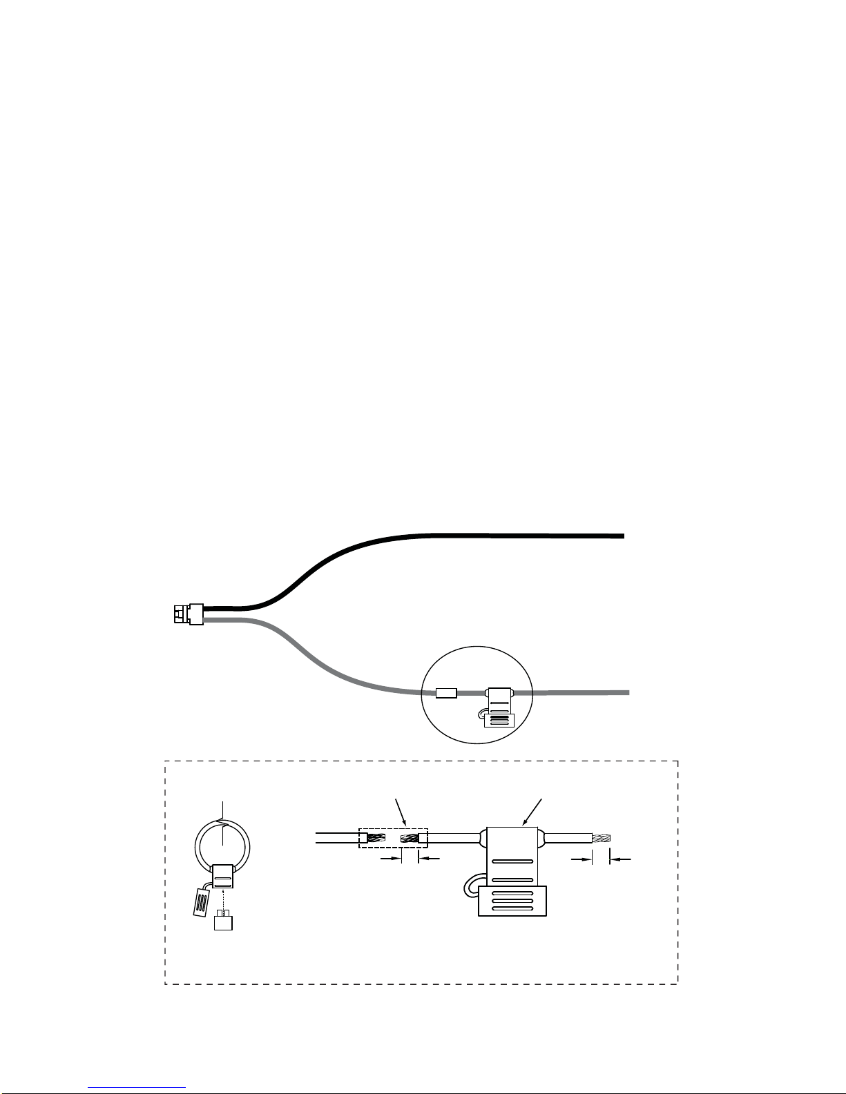
Carefully route the A+ wiring assembly from the radio connection to the1. battery compartment.
Using the supplied barrel crimp, attach the fuse holder (Item 4) as close to2. the battery as possible as shown in figure 1.
(NOTE: Only use 30 Amp rated fuses on the A+ line for dash mount/radio
core power cord. Only use 7 1/2 Amp rated fuse on the A+ line for remote
head power cords.)
Connect the red power lead (with fuse assembly) to the vehicles POSITIVE3. battery terminal. Using other positive voltage points is not recommended.
Connect the black lead to a good ground point on the chassis. Connection4. to the negative battery terminal is not recommended.
CUT HERE
Chasis
Ground
Vehicle
Battery
Red Wire
Black Wire
See Detail
3/4”
To Vehichle
Battery (+)
Red Wire
to Radio
1/4"
Barrel Connector (Item 7) Fuse Holder (Item 4)
DETAIL
- Install the fuse holder (Item 4) As close to the vehicle battery as possible.
- Strip one end to 1/4” and one end to 3/4”
- Fold the 3/4” exposed wire in half and crimp to red wire of the power cable
assembly using the barrel crimp connector (Item 7)
Blade Fuse
(Item 5)
Figure 1 - Power Cable Assembly
Page 4 RELM Wireless
KNG MOBILE INSTALLATION GUIDE
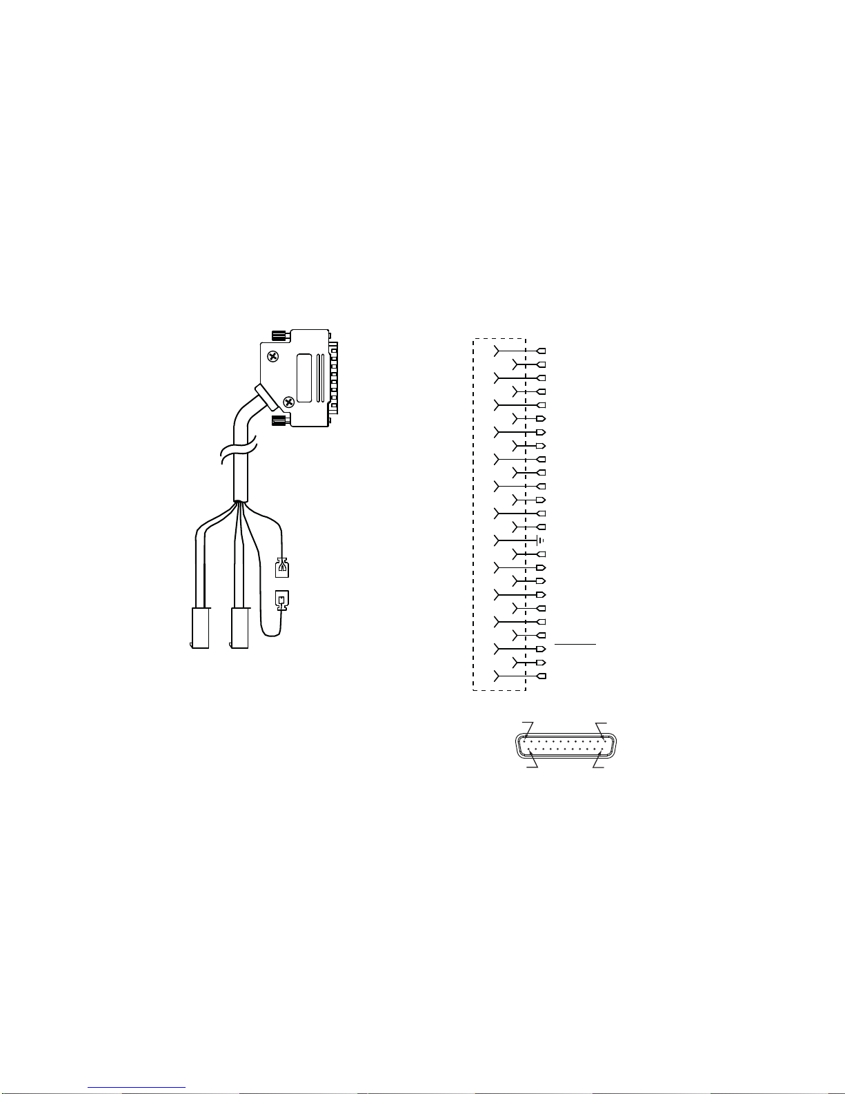
If vehicle ignition control of radio power up/power down is to be used,5. connect the red/white ignition sense line from the accessory cable to the
vehicle’s ignition. Leave the red wire disconnected. (See figure 2)
IMPORTANT: IF IGNITION SENSE WILL NOT BE USED, THE RED WIRE
MUST BE CONNECTED TO THE RED/WHITE WIRE OR THE RADIO
WILL NOT POWER-UP.
Route and connect any required accessory option controls to the accessory6. cable.
Pin 25
Pin 13
Pin 1
Pin 14
1
2
3
4
5
6
7
8
9
10
11
12
13
13
15
16
17
18
19
20
21
22
23
24
25
SPKR1+
SPKR1-
RF_USB_HOST_PWR
RF_USB_HOST_D+
RF_USB_HOST_D-
ACC_RS232_TXD
ACC_RS232_RTS
ACC_RS232_DSR
ACC_RS232_CTS
ACC_RS232_RXD
ACC_AUDIO_OUT
ACC_MIC
LOW_CURRENT_A+_OUT
FUSED_SWA+
IGNITION_SENS
EXT_EMERGENCY_INPUT
OPT_1_INPUT
OPT_2_INPUT
AUX_1_OUTPUT
AUX_2_OUTPUT
AUX_3_OUTPUT
ACC_PTT
SPKR2-
SPKR2+
Red Wire
(Fused A+, Pin 20)
See Note 1
Red/White Wire
(Ignition Sense, Pin 21)
See Note 1
NOTE 1: To enable vehichle ignition control ot
radio power up/power down, connect the
red/white ignition sense line to the vehichle’s
ignition. Leave the red wire discontected.
If ignition control is not used connect the red/white
wire to the Red wire.
REMOTE CONTROL HEADS DO NOT USE THIS
CONNECTION Relalys connected to Option outputs
3, 4 or 5 must be powered from fused A+
Figure 2 - Accessory Cable and Connections
Install your RF antenna and route the cable to the back of the dash mount/7. radio core install location.
Install the GPS antenna (if used) and route the cable to the back of the8. dash mount/radio core install location.
RELM Wireless Page 5
KNG MOBILE INSTALLATION GUIDE
4.2 SPEAKER INSTALLATION
KNG Mobile radios are not equipped with an internal speaker. Installation of at
least one KAA0261 external speaker is required. The dash mount/radio core
can accommodate two speakers. In addition, each remote control head can also
support dual speakers.
Speaker volumes are controlled independently by the volume knob on the
attached control head or radio.
Select a suitable install location for each speaker.1.
Use the template on page 15 or the speaker mounting bracket as a guide to2. drill 3 pilot holes.
After attaching the mounting bracket, secure the speaker to the bracket3. with the two side knobs.
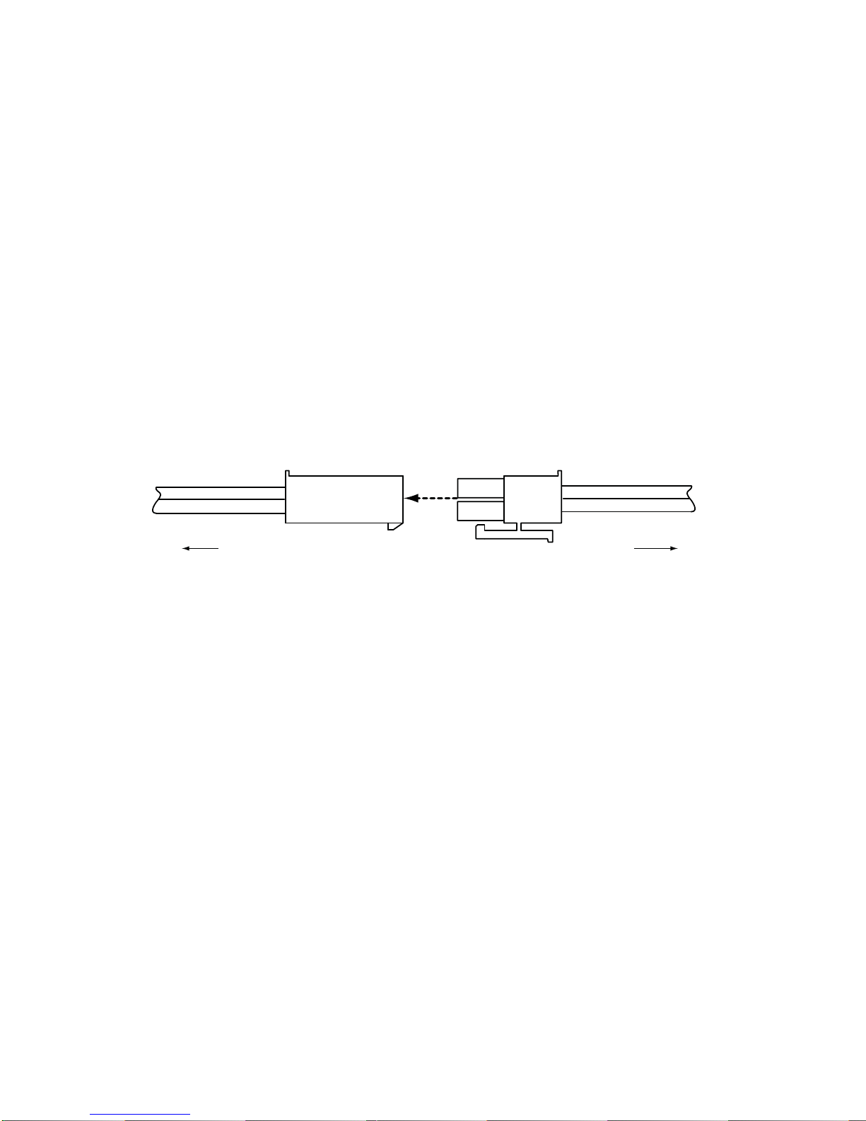
Once your speakers are installed, route the speaker connection wires to the4. mounting location for the desired radio or remote head.
Connect the speakers to the accessory connector. (See figure 3)5.
To Accessory Connector To Speaker
Figure 3 - Speaker Wire Connection
Page 6 RELM Wireless
KNG MOBILE INSTALLATION GUIDE
4.3 DASH-MOUNT/RADIO CORE INSTALLATION
Your KNG mobile radio can be configured as a stand alone dash-mount type
radio or used in conjunction with up to two KAA0660 remote control heads.
When used with a remote head, the main radio core remains operational.
If the main radio core is to be mounted in a hidden or inaccessible location,
RELM Wireless recommends the installation of a KAA0661 control cover (see
page 10).
NO. 26 DRILL (4 Places min.)
Ø 0.147
1.50
2.68
5.35
Figure 4 – KAA0630 Dash/Radio Core Recommended Hole Pattern
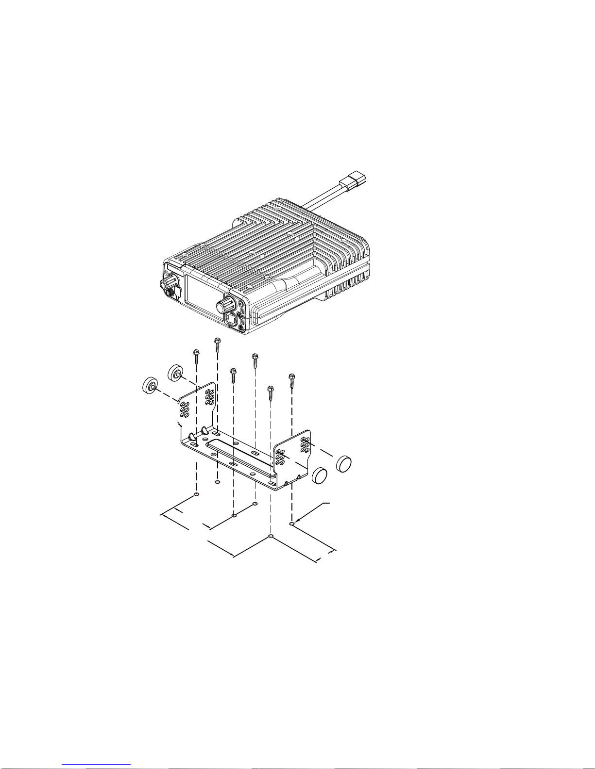
Drill 1/4” pilot holes through the mounting plate. A minimum of four holes is1. recommended. A mounting template can be found on page 11 or use the
mounting bracket as a template. Make sure the holes are free from the
metal flashing.
Fasten the mounting bracket to the chassis using the #10 self tapping2. screws (Item 8).
Connect the speakers and any other accessories to the 25-pin accessory3. cable. (See Figure 2)
RELM Wireless Page 7
KNG MOBILE INSTALLATION GUIDE
Attach and secure the accessory connector with a small flat blade screw4. driver.
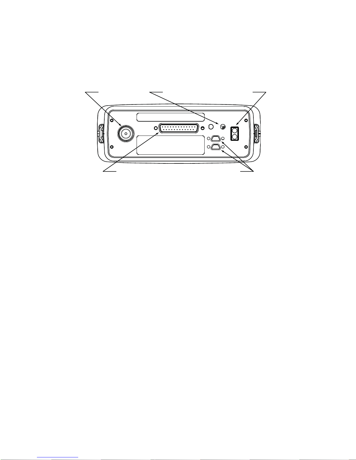
Attach the RF antenna (and GPS antenna if used) to the radio’s antenna5. port(s). (See figure 5)
Connect the power cable assembly to the DC Power input connection.6.
GPS Antenna Port
Type - MMCX
RF Antenna Port
Type - MMCX
Accessory Connector Remote Head Connectors
DC Power
Connection
Figure 5 - Dash Mount/Radio Core Back Panel Connections
Position the radio into the bracket at the desired angle.7.
Install and tighten the 4 mounting knobs (Item 2).8.
4.4 REMOTE-MOUNT CONTROL HEAD INSTALLATION
Installation of a KNG remote control head requires install kit KAA0638 hardware
kit and the proper cable kit to provide adequate cable for installation.
Remote Cable Kit Part Numbers
KAA0635 - 8 foot remote cable assembly•
KAA0636 - 17 foot remote assembly•
KAA0637 - 25 foot remote assembly•
Optional Equipment
KAA0261 Speaker Kit•
Prep the remote head power cable as described in Section 4.11.
Route the remote cable from the radio core location to the remote head2. location.
Attach the cable to one of the two remote head connectors on the back of3. the main unit. (See Figure 5).
Secure the remote cable with a small flat blade screw driver.4.
Drill 1/4” pilot holes through the mounting plate. A minimum of four holes is5. recommended. A mounting template can be found on page 13 or use the

Page 8 RELM Wireless
KNG MOBILE INSTALLATION GUIDE
mounting bracket as a template. Make sure the holes are free from the
metal flashing.
Fasten the mounting bracket to the chassis using the #10 self tapping6. screws (Item 3).
Connect the speakers and any other accessories to the 25-pin accessory7. cable. (See Figure 2)
NOTE: The volume of a speaker attached to a control head is controlled
independently by the control head. If no speaker is attached to the control
head the accessory connector is not required for radio operation.
Attach and secure the accessory connector with a small flat blade screw8. driver.
Attach an secure the remote power cable with a small flat blade screw9. driver.
Position the control head into the bracket at the desired angle.10.
Install and tighten the 2 mounting knobs (Item 7).11.
5 4 3 2 1
9 8 7 6 CTRL1_AUDIO_IN-
CTRL1_AUDIO_IN+
RF_PWRON
CTRL_RS485-
CTRL_RS485+
CTRL_POWER_HOLD
CTRL_AUDIO_OUT+
CTRL_AUDIO_OUT-
1
2
3
4
5
6
7
8
9
Figure 6 - Remote Head Connections
Control Head Address Assignment
If more than one control head is attached to the KNG, a address of “2” will need
to be assigned to one of the control heads. Use the following steps to set the
address:
Once the installation is complete, hold the Home button1. on the control
head while powering up the radio.
1. Control Head Address
2. Screen Calibration
3. Version
ESC NEXT PREV ENT
Configuration Menu At the configuration menu select “Control2.
Head Address”.
Use the up/down arrow button to select the3.
control head address.
Press ENT to set.4.
The control head will automatically cycle power and be ready for normal
operation.

RELM Wireless Page 9
KNG MOBILE INSTALLATION GUIDE
4.5 MICROPHONE MOUNTING
For proper operation of monitor modes, a microphone hanger clip must be used.
Mount the microphone hanger clip securely to the desired location. The KNG
mobile microphones have a self grounding hang-up button. No grounding is
required for the hang-up clip.
Drill 1/4” pilot holes through the mounting plate. A mounting template can1. be found on page 15 or use the hang-up clip as a template. Make sure the
holes are free from the metal flashing.
Fasten the mounting bracket to the chassis using self tapping screws.2.
To connect the microphone to the radio:
Align the notch on the microphone connector toward the top of the radio.1.
Gently slide the connector onto the radio’s microphone jack.2. DO NOT FORCE. EXCESS PRESSURE COULD DAMAGE THE
MICROPHONE.
Tighten the connection by screwing the microphone connector sleeve in a3. clockwise direction.
FINGER TIGHTEN ONLY
TO RADIO
MIC CONNECTOR
PART OF MICROPHONE
Microphone Connection Pinout
GND
Tx RS232
Key Data
+5V
Rx RS232
Mic -
Mic +
-PTT
1
2
3
4
5
6
7
8
8
5
2
7
1
4
Microhone
Pin Location
8
5
2
7
14
Radio
Pin Location
Figure 7 - Microphone Connections
4.6 ANTENNA INSTALLATION
Use only 50 ohm antenna in the proper frequency range. Make sure the
antenna is capable of handling the radio’s output power.
Install the antenna as instructed per the antenna’s manufacturer guidelines.
Keep the antenna free from other equipment and hardware. Keep the antenna
cable as short as possible and free from being pinched or in the way of other
mechanical hardware.
Page 10 RELM Wireless
KNG MOBILE INSTALLATION GUIDE
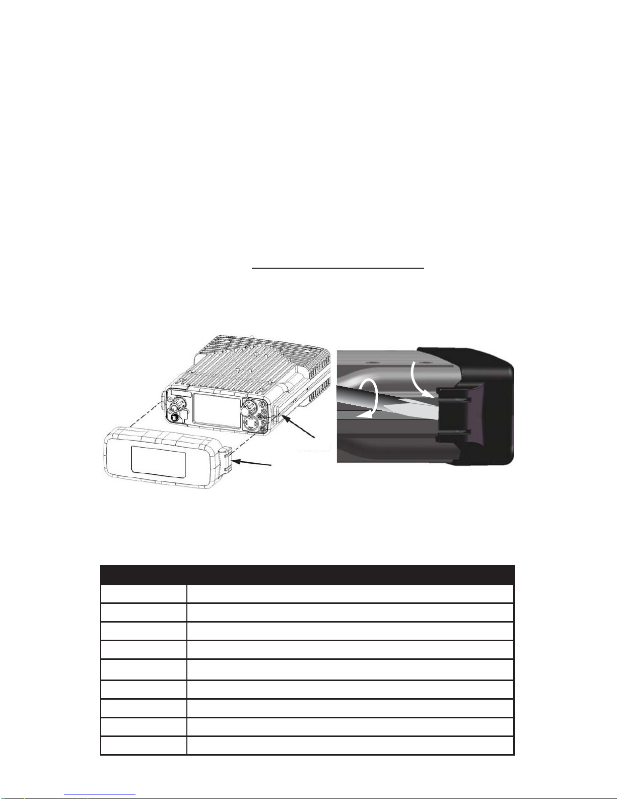
4.7 KAA0661 COVER INSTALLATION AND REMOVAL
Installation:
Line the radio knobs up with the openings inside the cover.1.
Slide the cover over the front of the radio until the tabs click into the side2. channels of the radio. (See Figure 8.)
Removal:
IMPORTANT: Angling the cover during removal could damage the radio knobs.
Release both tabs before removing the cover.
Use a flat blade screw diver to pry up the tab while gently pushing toward1. the front of the radio. (See Figure 8.)
When the tab pops free do not continue pushing the cover, perform the
same action on the other tab.
When both tabs are free pull the cover straight off the radio.2.
Channe
l
Tab
Figure 8 - KAA0661 Installation and Removal
4.8 INSTALLATION ACCESSORIES
Part Number Description
KAA0276 KNG Mobile Standard Microphone
KAA0290 KNG Mobile Keypad/Smart Microphone
KAA0621 KNG Mobile Speaker with Mounting Bracket
KAA0630 KNG Dash Mount/Radio Core Installation Kit
KAA0638 KNG Remote Head Installation Kit (Requires cable assembly)
KAA0636 8 ft. Remote Cable Assembly
KAA0637 17 ft. Remote Cable Assembly
KAA0638 25 ft. Remote Cable Assembly
KAA0661 Display Cover

RELM Wireless Page 11
KNG MOBILE INSTALLATION GUIDE
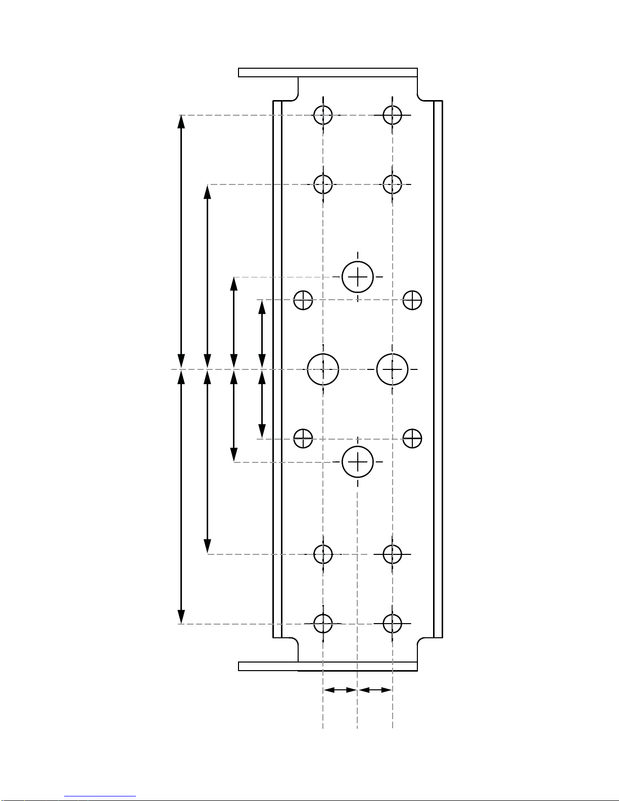
4.8 MOUNTING TEMPLATES
1 5/16”
2 5/8”
3/4”
3/4”
1 5/16”
2 5/8”
Figure 9 - KAA0630 Dash Mount/Radio Core Mounting Template

Page 12 RELM Wireless
BLANK PAGE
RELM Wireless Page 13
KNG MOBILE INSTALLATION GUIDE
3/8”
3/8”
2.75” 2.75”
2” 2”
1” 1”
3/4” 3/4”
Figure 10 - KAA0638 Remote Mount Mounting Template

Page 14 RELM Wireless
BLANK PAGE

RELM Wireless Page 15
KNG MOBILE INSTALLATION GUIDE
1” 1”
1/2”
3/8”
3/8” Diameter
Figure 8 - KAA0261 Speaker Mounting Template
.18”
1.6”
.68”
1.44”
Figure 11- KNG Microphone Clip Mounting Template

© 2012 RELM Wireless Corporation
PN 7001-31046-500 Rev C


