BPS CLIMA FI-1934-1810-R00 User manual
Pag. 1/2 Ref.: PSD; Canaliz.Medie/Medium units Istruzione di montaggio – Assembling instruction Note: \ Code: FI-1934-1810-R00
Pressostato aria per sezioni filtro (Rif. Versioni F-H- )
Air pressure switch for filter sections (Ref. Versions F-H- )
IT Originale
EN Translation
Istruzione N° – N° Instruction
FI-1934
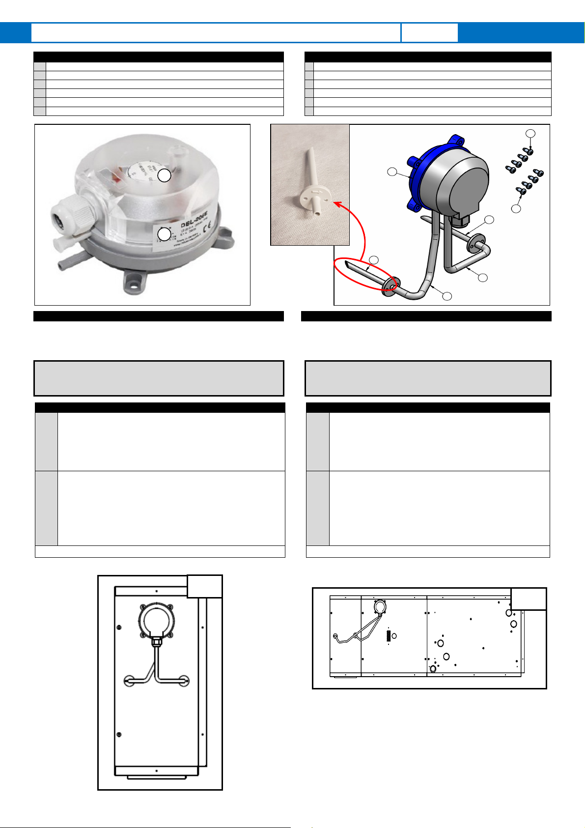
COMPONENTI FORNITI SUPPLIED ITEMS
1 n 1 Pressostato aria 1
n 1 Air pressure switch
2 n 2 Presa pressione 2
n 2 Pressure probe
3 n 2 Tubetto in silicone da Ø 8 x 300 3
n 2 Silicone tube Ø8 x 300
4 n 4 Viti autofilettanti da Ø 3.2 x 9 fissaggio pressostato 4
n 4 Self-tapping screws Ø3.2 x 9 for pressure switch fixing
5 n 4 Viti autofilettanti da Ø 3.2 x 9 fissaggio prese pressione 5
n 4 Self-tapping screws Ø3.2 x 9 for fixing the pressure points
\ Imballo dell’accessorio e la presente Istruzione di montaggio \
Packaging of the accessory and hereby Assembly instruction
DESCRIZIONE
DESCRIPTION
Pressostato aria adatto per il controllo della pressione differenziale,
impiegato sulle sezioni filtro per la segnalazione di un’eventuale
ostruzione o intasamento. Installato in ambienti con aria e gas non
corrosivi e non infiammabili.
Air differential pressure switch used with air filter section to advise when a
filter starts clogging. Installed in environments with non-corrosive and
non-flammable air and gas.
Questo foglio istruzioni è parte integrante del libretto dell’unità sulla
quale viene installato l’accessorio.
A tale documento si rimanda per le AVVERTENZE GENERALI.
Hereby instruction sheet is an integral part of the unit’s manual on which
the accessory is installed.
Please refer to hereby manual for GENERAL RECOMMENDATIONS.
L’installazione deve essere effettuata da personale qualificato. The installation must be performed by qualified personnel.
Note INSTALLAZIONE
INSTALLATION Note
Nota
1
Fissa
re il corpo del pressostato (1) nella posizione ritenuta più
adeguata in funzione della configurazione e delle esigenze di
installazione, ponendo particolare attenzione affinchè le viti non
interferiscano con elementi interni (es.filtro). Ad esempio:
A) Installazione sulla spalla del filtro.
B) Installazione sull’unità in prossimità della morsettiera,
compatibilmente con L tubi presa pressione.
Note
1
Fix the
pressure switch
(1) in the
most ap
propriate
position
according to the configuration and installation requirements,
paying particular attention that the screws don’t interfere with
internal elements (filter). For example:
A) Installation on the filter shoulder.
B) Installation on the unit near the terminal board,
compatibly with L pressure intake pipes.
Nota
2
Il valore di taratura del pressostato differenziale (tramite la
manopola M) varia a seconda:
-della tipologia del filtro (piano/ondulato/a tasche),
-della taglia/modello/versione,
-del punto di lavoro in cui viene fatta lavorare l’unità.
In tutti i casi, il valore MAX della taratura di intervento non deve
superare il valore delle Pdc aria filtro sporco indicate sulla
documentazione dell’unità.
Il pressostato è compatibile con gli accessori QA-1 e QA-3*
Note
2
The cali
bration
va
lue of t
he
differential pressure switch
(using the
knob M) varies according to:
- the type of filter (flat / undulated / pocket bags),
- the size / model / version,
- the unit working point.
In all cases, the MAX value of the intervention point must not
exceed the air pressure drops value of the dirty filter indicated on
the unit documentation. The pressure switch is compatible with
accessories QA-1 and QA-3 *
*QA-1: quadro con blocco unità a seguito intervento del pressostato, con obbligo riarmo manuale di reset;
QA-3: quadro di segnalazione con spia verde corretto funzionamento + spia rossa allarme intervento pressostato * QA-1: panel with unit block following intervention of the pressure switch, with manual reset obligation;
QA-3: signaling panel with green light for correct operation + red light for intervention pressure switch;
B
1
M
A
1
2
2
3
3
4
5
Pag. 2/2 Ref.: PSD; Canaliz.Medie/Medium units Istruzione di montaggio – Assembling instruction Note: \ Code: FI-1934-1810-R00
Pressostato aria per sezioni filtro (Rif. Versioni F-H- )
Air pressure switch for filter sections (Ref. Versions F-H- )
IT Originale
EN Translation
Istruzione N° – N° Instruction
FI-1934
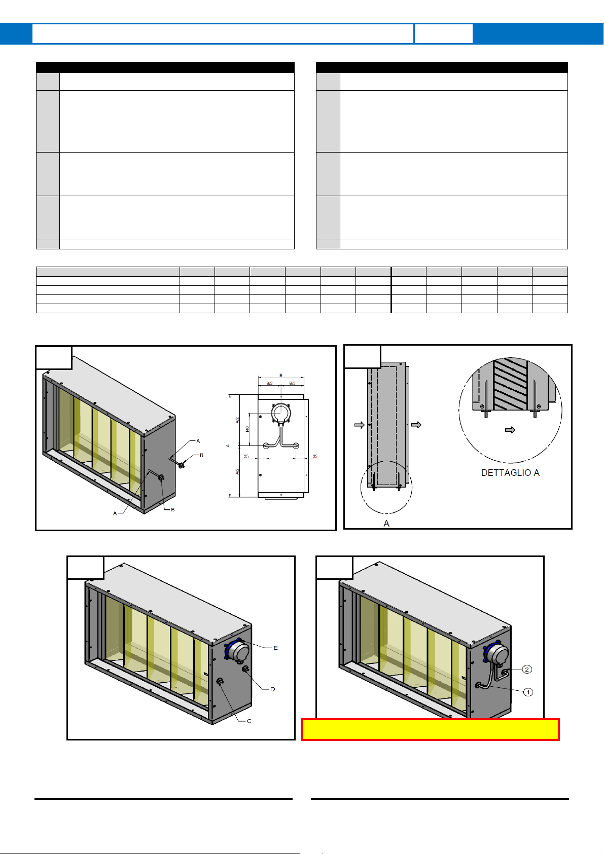
INSTALLAZIONE
INSTALLATION
1 Forare con una punta da trapano Ø8 nella posizione “A”
secondo, ad esempio, le quote rilevabili nella fig.1 1 Drill with a Ø8 drill bit in position “A” according, for example, to
the dimensions shown in fig.1
2
Inserire le prese pressioni sino al battente (fig.2) facendo
attenzione che la punta inclinata sia posizionata nel senso di
marcia della aria (dettaglio “A”).
Quindi segnare le posizioni di fissaggio delle prese di pressione e
forare con una punta Ø3.
Infine, avvitare le viti autofilettanti da Ø3,2x9 per fissare le 2 prese
di pressione.
2
Insert completely the pressure probe(fig.2) making sure that the
inclined tip is positioned in the direction of air flow (detail “A”).
Mark the fixing position of the pressure point and drill with a Ø3
bit.
Finally, screw the self-tapping screws Ø3,2x9 to fix the 2 pressure
probe.
3
Posizionare il pressostato aria secondo le quote della fig.1.
Segnare la posizione delle viti.
Forare con una punta Ø3.
Avvitare le viti autofilettanti da Ø3,2x9 per fissare il corpo del
pressostato.
3
Position the air pressure switch according to the dimensions in
fig. 1. Mark the position of the screws.
Drill with tip Ø3.
Screw the self-tapping screws Ø3,2x9 to fix the pressure switch.
4
Collegare i tubetti di silicone:
a) Presa pressione (fig.4 n 1) con “P1 + “ del pressostato aria.
b) Presa pressione (fig.4 n 2) con “P2 – “ del pressostato aria. 4
Connect the silicone tubes:
a) Pressure probe (fig. 4 n 1) with “P1 +“ of the air pressure
switch.
b) Pressure probe (fig. 4 n 2) with “P2 -“ of the air pressure
switch.
Nota
Eseguire il collegamento elettrico seguendo lo schema elettrico.
Nota
Make the electrical connection following the wiring diagram.
Taglia
1.. 2.. 3.. 4.. 5.. 6.. 12.. 13.. 14.. 15.. 16..
Per tutti/ for all A[mm]
380 440 440 480 570 570 440 440 480 600 600
Piano piano/Flat filter
B[mm]
150 150 150 150 150 150 150 150 150 150 150
Filtro Ondulato/Undulated filter
B[mm]
200 200 200 200 200 200 200 200 200 200 200
Filtro a Tasche/Pocket bags filter
B[mm]
500 500 500 500 500 500 500 500 500 500 500
Per ulteriori informazioni rivolgersi al nostro ufficio tecnico che rimane a disposizione
per qualsiasi chiarimento e per la progettazione di soluzioni personalizzate.
For further information make reference to our Technical department, which is
available for explanations and for the design of customised solutions.
RISULTATO FINALE - FINAL RESULT
1 2
3 4
Popular Switch manuals by other brands


SMC Networks
SMC Networks TigerStack user guide

ETI
ETI BU-DUSK-1 quick start guide

NETGEAR
NETGEAR FSM7326P - ProSafe Managed Switch Specifications

Alstom
Alstom DS Agile H38 Series Installation and operating instructions

Intellinet
Intellinet 561082 instructions

Freedom9
Freedom9 freeConnect 2400 user manual