Table of Contents
1About this instruction .............................................................................................5
1.1 Scope .....................................................................................................................................................5
1.2 Document conventions........................................................................................................................5
2Safe use of VCM-3 / VCM-3 Ex................................................................................5
2.1 Disclaimer of liability............................................................................................................................5
2.2 Intended use..........................................................................................................................................5
2.2.1 General Information................................................................................................................................................6
2.3 General warnings..................................................................................................................................7
2.3.1 Staff requirements..................................................................................................................................................7
2.4 Grounding information.........................................................................................................................7
3Product Description ................................................................................................8
3.1 Main functionality .................................................................................................................................8
3.2 Overview of the VCM-3 unit .................................................................................................................9
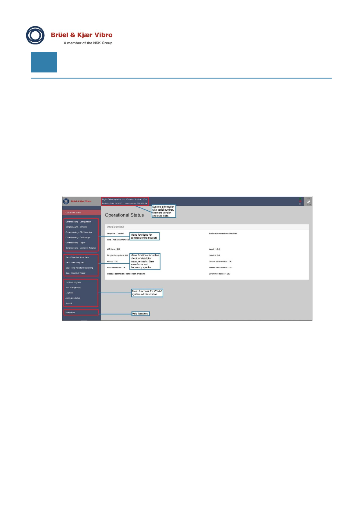
3.3 The VCM-3 Homepage........................................................................................................................10
3.4 Technical specification summary.....................................................................................................11
4Mechanical installation .........................................................................................12
5Basic operation of the VCM-3...............................................................................14
5.1 First time the VCM-3 is powered up..................................................................................................14
5.2 About LED indicators.........................................................................................................................14
5.3 Power Up/Down...................................................................................................................................15
5.4 Reset to default IP address................................................................................................................17
6Power connections................................................................................................18
6.1 Power connection –Supply current .................................................................................................18
6.2 Power connection –External sensor power....................................................................................19
7Termination of sensor signals..............................................................................20
7.1 Electrical Parts....................................................................................................................................20
7.2 Sensor connection terminals ............................................................................................................20
7.3Shielding..............................................................................................................................................21
7.4 Constant current line drive accelerometers (CCS) channel 1-12 ..................................................22
7.5 Brüel & Kjær Vibro AS-247 dual axis accelerometers on channel 11-12.....................................23
7.6 Brüel & Kjær Vibro AS-247 dual axis accelerometers on channel 1-10.......................................24
7.7 Displacement sensors (proximity probes) channel 1-10................................................................25
7.8 Displacement sensors (proximity probes) channel 11 and 12.......................................................26
7.9 Displacement sensors (proximity probes) channel 13-16..............................................................27
7.10 4-20 mA input channel 17-24 .............................................................................................................28
7.11 Speed sensor, proximity switch, PNP and NPN type......................................................................29
7.12 Rogowski probe for current and power measurements.................................................................31
7.13 Digital inputs .......................................................................................................................................32