Braaap Moto3 User manual

1Moto3 User Manual
moto3 User manual

2Moto3 User Manual
Preface
Firstly, thank you for purchasing the braaap Moto3.
This is an introduction to the basic structure, adjustment methods and maintenance of the moto3. This manual is designed
to help you get to know your motorcycle and teach you how to maintain it to its optimum performance.
This type of motorcycle has reached the standard of GB 14621-2011<Limitation of exhaust emission for motorcycle & trail
bike and their measurement method (Double idle state me1hod)>, GB 14622-2007< Limitation of exhaust emission for
motorcycle(Method under operating mode), The 3n1 phase of China)> and GB 20998-2007< Limitation of fuel evaporative
pollutants for motorcycle & trail bike and their measurement method>, all the standards above has been reached when the
products left factory.
We may make structural improvements to the motorcycle in the future. The pictures and contents of this service manual may
be slightly different to current products. Products herein are subject to change without notice at any time.
Warning-Caution:
Please carefully read this manual and keep all of the essentials in mind. The words “Warning”, “Caution” are an emphasis
on important subjects that may need extra attention for your own safety.
Warning: This word is involves driving safety, please read these sections carefully.
Caution: This word is for matters that need attention related to operation and maintenance of the motorcycle.

3Moto3 User Manual

4Moto3 User Manual
CONTENTs
UserAgreement.............................................................................................................5
I. Riding Safety..............................................................................................................6
II. Main Technological parameters.................................................................................9
III.Structure of the motorcycle......................................................................................11
Parts name.................................................................................................................12
Moter indicator lamp...................................................................................................14
GulpValve....................................................................................................................15
IV.Operation................................................................................................................16
Powerswitch................................................................................................................16
Fuelswitch...................................................................................................................16
Enginestart-up.............................................................................................................17
Engine Run In.............................................................................................................17
Right switch assy........................................................................................................18
Left switch assy...........................................................................................................19
Gearshifting................................................................................................................20
V. Matters need attention in driving.............................................................................21
VI.Checking, adjustmentandmaintenance..................................................................22
Oil check.....................................................................................................................22
OilReplacement..........................................................................................................23
Oil tank washing..........................................................................................................23
Checking the spark plug.............................................................................................23
Checking and replacing the air filter............................................................................24
Adjusting the throttle cable..........................................................................................25
Fine Tuning the Carburetor..........................................................................................25
Checking and adjusting the valve cap.........................................................................26
Adjusting the clutch.....................................................................................................27
Adjusting the brake pedal............................................................................................27
Kick stand...................................................................................................................27
Front and rear disc brake maintenance......................................................................28
ChainAdjustment........................................................................................................30
Adjusting the braking switch........................................................................................30
Checking the battery...................................................................................................31
Replacing the fuse......................................................................................................31
Tires............................................................................................................................32
Tire pressure...............................................................................................................32
Replacing the headlight..............................................................................................32
Table of fastening parts torque,...................................................................................33
Maintenance periodic table.........................................................................................33
VII. Washing................................................................................................................35
VIII. Maintenance during stops....................................................................................36
Storage maintenance..................................................................................................36
Return to use..............................................................................................................37
IX. Electric start explanation........................................................................................37
X. Electrical schematic diagram..................................................................................38

5Moto3 User Manual
User agreement
There is a wide range of spare parts available in the after-sales market. We are unable to test and approve all of these parts.
Unsafe spares may cause damage to the bike and may cause harm to the rider/riders. If you wish to source spares or cus-
tom parts outside of braaap’s range then please contact your local braaap service agent to ensure the safety of the rider/
riders and the performance and longevity of the motorcycle.
If installing spare parts you can follow these steps as a rough guide. If you are still unsure please contact your local braaap
service agent.
1. Any accessories should be as close to the bikes body and center of gravity as possible.
2. Check ground clearance and angle of installation accessories, unsuitable installation may decrease safety degree, hin-
dering mechanical systems such as shock absorber, steering and controlling parts are not allowed.
3. Accessories’ installation on handle bar or front fork may lead to serious imbalance. Extra weight on front end may de-
crease sensitivity of turning, shock on front wheel and instability during driving. Minimum the weight of accessories to
be installed on handle bar and front fork.
4. Windshield, backrest, saddle bag, suitcase are head-wind parts and may cause instability during driving, especially in
crosswind or go across with oversize vehicle. If there is bad installation or poor designed accessories, driving safety may
endangered. So, special attention should be paid on selection and installation of accessories.
5. Some accessories may cause deviation for driver’s seating position, which not only a limit to his activity scope but also
to his operational capability.
6. Extra electrical accessories may cause overloading, of which serious one may damage wires, or lead to power-<>ff and
endanger safety.

6Moto3 User Manual
Riding Safety
Safe riding
Before starting the engine, please carefully read the “pre riding inspection” and check the motorcycle to ensure the safety
of the riders. The motorbike rider must have there current motorcycle license. Riding without a license is strictly prohibited.
Please wear hi-visibility clothing, keep a safe distance between yourself and other motor vehicles, and use your indicators,
horn and other signaling devices correctly.
Please adhere to the correct speed when riding. Speeding may cause traffic accidents and or harm to others and yourself.
When riding a motorcycle, please put both hands on the handlebars and both feet on the pedals. The passenger should hug
the driver with both hands and put both feet on the back pedals.
Protective Article
Please select and wear a new helmet that adheres to Australia’s standards. Before riding please unsure that you have a safe
helmet, leather boots and appropriate clothing. Please unsure that any passengers that you ride with have similar protective
gear.
Cargo Loading
Please adjust the rear tire pressure and shock absorber according to the loaded weight and road conditions. This will ensure
that all cargo and/or people are solidly fixed and balanced.
Please do not tie any large and heavy items to the handlebars, front forks or front mudguard. As it may make the motorcycle
hard to steer.

7Moto3 User Manual
Accessories
All braaap accessories have been tested and deemed safe to use.
Please make sure to double check with your local service center if you are purchasing other accessories as they may not
be safe.
If installing new accessories do not let them interfere with the drivers sight, ground clearance or steering.
Please do not add any extra electrical accessories. The may cause an electrical overload that could damage the bike and
its electrics.
Warning
1. Altering the circuitry or installing anti theft devices is forbidden.
2. Copper wire or fuses with a different capacity are not to be used if a fuse blows.
3. When the motorcycle has been switched off please unsure that you turn the fuel line off as well.
4. Max loading capacity of luggage is 5kg.
5. Certification should be moisture proof.
Our company is not responsible for the motorcycle damages caused from the above actions.
Checking before driving
Before driving, Check as following details:
Items to check Content of checking
Steering stem Flexible turning, no clearance and loosening
Brake The brake light should be shining when the brakes are applied
Fuel levels Make sure that you have enough fuel for the journey ahead.
Gear box Check that the oil level is at the correct level, ad more when necessary
Throttle Throttle lever and cable should have suitable clearance of smooth refueling and sensitive turning-off.
Clutch Suitable clearance and no binding
Tire Correct air pressure, no crack and wound
Transmission chain Suitable tightness with appropriate lubrication
lights and horn Check the performance of lights and horn
Oil Check oil gauge and confirm correct oil level

8Moto3 User Manual
Riding Essentials
Warning
1. We suggest that you find a nonpublic road to practice on in your initial stages of riding this motorcycle until you have
the necessary skills to control and operation the motorbike.
2. Driving with one hand on the handlebars is very dangerous. make sure both of your hands and feet are in the correct
riding position at all times.
3. Do not brake through a corner. Reduce to appropriate speed before taking the corner.
4. When the roads are wet or icy please allow for extra time to slow down before the corner.
5. Proceed with extra caution when exiting a tunnel, in a valley, passing a truck or when it is generally windy.
6. Always comply with traffic laws and speed limits.

9Moto3 User Manual
Main parameters
Model Data MODEL Data
Length 2030mm Braking deceleration Follow GB20073
Width 720mm Maximum gradeability >25”
Height 1120mm Bore x Stroke 65.5x67
Wheel base 1345mm Pressure ratio 9.0:1
Curb weight 153kg Maximum net power/Rotational speed 13kw/8000r/min
Load capacity I50kg (With driver) Maximum torque/Rotational speed 17N.m/6000r/min
Allowed maximum weight 303kg Idling rotational speed (1500+150)r/min
Load capacity of front axle 107kg Working volume of Cylinder 250ml
Load capacity of rear axle 196kg Spark plug D8EA
Size of front tyre 110/70-17 Clarence of spark plug (0.6-0.7)mm
Size of rear tyre 140/70-17 Air inlet valve: (0.04-0.06)mm
Maximum designed speed 115km/h Air outlet valve: (0.04-0.06)mm

10 Moto3 User Manual
Main parameters (Additional)
Model
Fuel consumption
Oil capacity
Fuel tank volume
Speed ratio transmission box
1st gear
2nd gear
3rd gear
4th gear
5th gear
6th gear
Terminal transmission ratio
Primary transitional ratio
Data
<2.91L/100km
1.2L
15.5L
3.083
2.063
1.450
1.130
0.957
0.815
3.231
3.091
Model
Fuse
Headlight
Taillight/Brake light
Front position light
Front turning signal
Rear position light
Battery
Rear turning signal
Ignition mode
Data
15A/15W
12V-35Wx2/55W
12V-0.34W/1.4W
12V-2W
12V-1.2Wx2
12V-0.34W
12V7Ah
12V-0.25Wx2
CDI electronic ignition
11 Moto3 User Manual
Structure of motorcycle
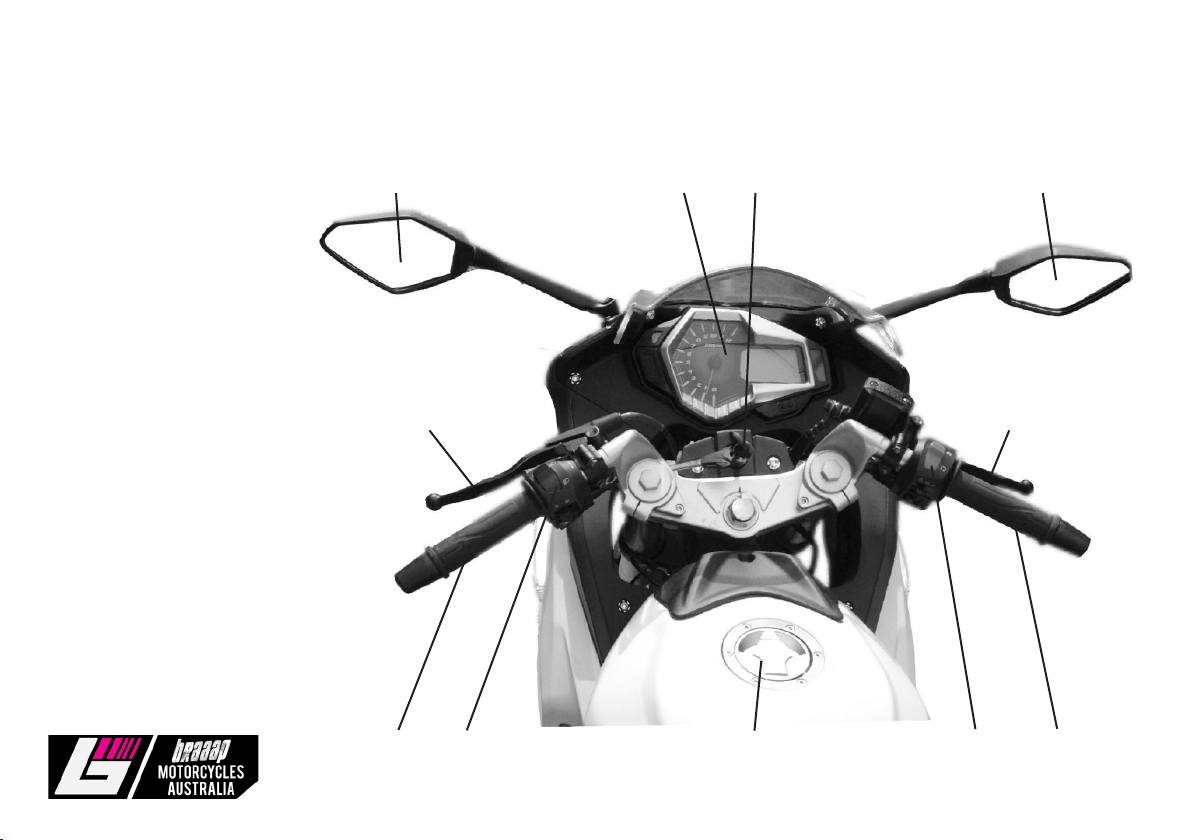
Parts name
1. Clutch lever
2. LH rear mirror
3. Speedometer
4. Power switch
5. RH rear mirror
6. Front brake lever
7. LH handlebar
8. LH handlebar switch
9. Fuel tank lock
10. RH handlebar switch
11. Throttle grip
2 3 4 5
1 6
7 8 9 10 11

12 Moto3 User Manual
Parts name Body
1. Headlight 1 2 3 4 5
2. Rear-view mirror
3. Fuel tank lock
4. Fuel switch
5. Rear indicators
6. Rear wheel
7. Rear shock absorber
8. Engine type and factory number
9. Gearshift pedal
10. Front shock absorber
11. Front disc brake
12. Front wheel
12 11 10 8 9 7 6

13 Moto3 User Manual
1. Muffler
2. Rear disc brake
3. Seat assy.
4. Rear braking pedal
5. Position of brand plate (Name plate, right side of frame)
6. Identification No.(VIN) Position (Right side of standing tube)
7. Gulp valve
7
1 2 3 4 5 6

14 Moto3 User Manual
Motor Indicator Lamp
Ref No. Parts name Note
1. Speed meter Indicates running speed, unit: km/h.
2. Odometer Indicates total mileage.
3. Fuel indicator When the needle is point at F it means the fuel tank is full, when it is pointing at the red
zone it means the fuel tank is low.
4. Gear indicator This Indicates which gear the motorcycle is currently in.
5. Tachometer Indicates the rotational speed of engine (r/min).
6. Right turning signal Indicator light flashes when turning right.
7. High beam This light flashes when you turn on the high beam.
8. Neutral indicator This light flashes when you are in neutral gear.
9. Left turning signal Indicator light flashes when turning left.
Warning 7 5 3 8
When indicating be sure to switch the indicator off
9 4 2 1 6

15 Moto3 User Manual
Gulp valvel
Functional introduction for secondary gulp valve of emission use with State III standard:
Connect air filter with air inlet tube, and then, connect air outlet tube to metal tube on the cylinder head. Connect the
negative pressure tube of the gulp valve with the air inlet tube on engine, control the entry of air into the exhaust pipe
through changing negative pressure in air inlet tube on the engine, decrease CO, HC, and Nox.
1. Negative pressure tube on gulp valve
2. Air inlet tube
3. Air outlet tube

16 Moto3 User Manual
IV. Operation
Power Switch
Position Function Note
On For parking (all circuit cut off) Key could be removed
Off For starting up and driving Key can’t be removed
Lock For locking Steering stem Key could be removed
Warning
When in locked position, do not push the motorcycle. As the
steering is locked and the motorcycle may loss its balance and
cause harm to the bike and/or the person or people pushing it.
Fuel switch
1. Filling the tank with fuel
Refer to the specifications for fuel tank capacity. Place the
Vehicle on its main stand, unscrew the fuel cap and fill the
tank with fuel.
After filling, tighten the fuel tank cap by aligning the ^ mark on
the cap with that on the fuel tank
Caution
Use unleaded or low-lead gasoline fuel graded #90 or higher.
2. Use of the fuel valve (switch on fuel tank)
1. open
2. closed
3. reserve
Caution
if the fuel tank valve lever is in the “open“ position quite often,
excessive fuel will enter the carburetor and may even flow into
the engine. If the engine is started in this condition it may cause
sever damage to the engine.
function
when the fuel cock is set
to the position, the fuel
passage is open
When the fuel line is set
to this position the fuel
line is closed
when the fuel cock is set
to this position the fuel in
reserve is being used
position
open
Closed
reserve
remarks
The fuel supply is turned
on
the fuel supply is cut off
the fuel in reserve is used
only after the normal fuel
supply has run out.

17 Moto3 User Manual
Engine stop
1. Loosen throttle lever to decrease the rotational speed of
engine.
2. Put the bike into neutral.
3. Turn the ignition switch to “OFF”
4. Turn the fuel valve ”OFF”
Engine run in period
For a new vehicle, the initial 1,000kms is the wear-in
period. In this period, the following items should be taken into
account:
1. Do not carry heavy goods and attempt to climb steep
slopes.
2. Do not exceed 50km.
3. Warm up the engine for 3-5min each time so as to
adequately lubricate the engine before each ride.
4. For the first 500kms do not go above 50kms an hour.
From 500-1000kms do not exceed 55kms
Warning
Do not start the engine in the room with poor ventilation or without ventilating device because carbon monoxide is very toxic.
Do not get off the motorcycle with the engine running if noone is around to guard it.
Engine Start-UP
1. Put key in ignition switch in the position of “ ”
2. Put the emergency stop switch in the position of “ ”
3. Confirm neutral position (make sure the neutral
indicator light is on).
4. Check the amount of fuel.
5. Turn the fuel valve cock to “Open”
Cold starting:
1. Raise up the choke lever on the carburetor (Tum off
choke valve).
2. Turn throttle 1/8,-1/4 of a turn.
3. Use electric or kick starting.
4. Slightly turn throttle lever, use rotational speed of
engine to warm the bike up.
5. when bike is warmed up, turn choke lever downward,
completely open the choke.
Caution
Make sure the engine is in neutral when starting otherwise
an accident may occur. When warming up the bike do not
rev the engine. Let it idle until it gets warm.

18 Moto3 User Manual
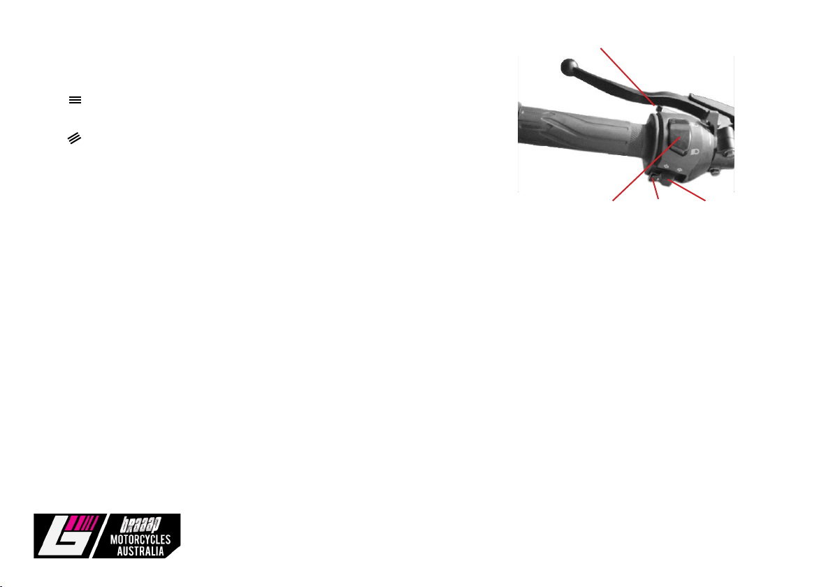
Right Switch Assy
(Electric starting is a little different to kick starting.)
1. Headlight switch
There are 3 positions on the headlight switch, i.e., “ “ “P “ and “ .“ (white
point sign)
“ “: Headlight, taillight and meter light are lit up.
“P “: Taillight, position light and meter light are lit.
“ .“: Headlight, Taillight, position light and meter light are off.
Cation
Headlight and taillight are not lit until the motorcycle is started.
2. Electric start button (only for electric start vehicle)
Electric start button is located under headlight switch. When the emergency off switch is set to the “ “ position and the
engine is in neutral gear. Push this button to start the engine.
3. Emergency shut off switch.
When engine is started the emergency shut off switch is normally set to the “ “ position. In emergency situations the
emergency off switch should be set to the “ “ position so as to shut off the power supply to the engine.
Warning
When engaging the electric start be sure to hold it in for no longer than 5 seconds at a time as a discharge can make the circuits and starter motor heat
abnormally. If the starter motor is not starting the engine after several attempts, stop and check the oil supply and starting circuit system.
(1) Headlight switch
(2) Electric start button
(3) Emergency shut off switch
1 2 3
19 Moto3 User Manual
Left switch assembly
1. Beam switch
D position indicates that the headlight is on high beam.
D position indicates that headlight is on low beam.
2. Indicator switch
<-- Position indicates that the left indicator is on.
---> Position indicates that the right indicator is on.
3. Horn
Push this button to get a loud sound from the horn.
4. High beam signal switch
Used for cutting in.
Warning
Use the indicators to change lanes and make turns. Be sure to turn the indicator off once you have made the turn.
(1) Beam Switch
(2) Indicator switch
(3) Horn
(4) High beam signal switch
1 2 3
4

20 Moto3 User Manual
Gear shifting
Preheat engine to make it run normally.
1. When the engine is at idle speed, engage the clutch (hold the clutch lever in) and push the gearshift pedal with your foot
to change gear. Enter the low gear (1st gear) position.
2. Gradually Increase the rotation speed of the engine while slowly releasing the clutch lever so that the bike starts to
slowly move forward.
3. Once the bike has reached a balanced running state, reduce the rotation speed of the engine then engage the clutch,
then raise the gear shift pedal to the 2nd gear position.
The same method can be used for the rest of the gears.
International Six-speed
6 Reverse gear
5
4
3
2
N Forward gear
1
Table of contents
Other Braaap Motorcycle manuals


