Bradcot MODUL-AiR User manual

1 | P a g e
MODUL-AiR ERECTING INSTRUCTIONS (V-1.10)
WE URGE YOU TO TAKE THE TIME TO STUDY THESE INSTRUCTIONS IN EVERY DETAIL!
** YOU MUST KEEP YOUR BOX WHILST YOUR AWNING IS UNDER WARRANTY **
This is a very large box which we have made especially for our iR awnings.
You will struggle to find a similar box if you choose NOT to keep the original.
We will be nable to collect yo r awning whilst nder warranty, if yo do not keep this box.
Firstly, check the contents of each box within 7 days of receipt. If for any reason some items are
found to be missing then it’s important we know which box they are missing from in order to send
you the correct quantity. check list can be found at the end of this document. This is a good time
to familiarise yourself with the various component parts of your awning.
INSTRUCTIONS
We recommend that the draught cloth and wheel arch cover are fitted first. This helps to avoid
catching parts of the awning within the wheel arch or under the caravan. (NB. Grease, oil, tyre
dressing etc, cannot be removed from the canvas and is not covered by the warranty)
IMPORTANT Ensure that all air valves are f lly closed (diagram 1). This can be achieved by pressing
in the valve insert within the valves core with your finger or thumb and turning it clockwise. (Do not
se pliers or similar to do this, it will damage the valve and this wo ld not be covered by o r
warranty.) The valves are fitted to the bottom of each main iR beam. (To test, push the insert
down with your finger and it should spring back up following your finger out of the valve.) See
below;
When inflating your new AiR awning, we recommend that for the first two or three times, you leave the dust
caps OFF the valves whilst inflating. Once you are happy that the awning is fully inflated, you can then replace
the dust caps. We recommend inflating using the centre valve on the 260 and 0 models or either of the
centre valves on the 90 model.
If whilst inflating the awning, any of the valves appear to be not fully closed, push in and out a couple of times
with your finger to rectify this.
V LVE CLOSED (Ready for inflation) V LVE OPEN (Ready for deflation)
Diagram
1
Diagram 2
2 | P a g e
The Modul- iR awning has both detachable side and front panels. It is generally easier to fit and
remove the awning from the caravan with all panels removed however: It is important that all
panels are fitted prior to any pegging or inflating of the awning. This is absol tely necessary to
ens re the correct awning footprint is established and the t bes inflate correctly within that
footprint.
Thread the awning piping into the caravan channel. You will need assistance here, one feeding the
channel, the other pulling the awning along the caravan. Do not pull the awning by the inflatable
beams as this will damage them. Most caravans are fitted with “feed in” points at the base or at
head height of the channel. The Modul- iR allows for the right hand facing side panel to also fit into
the caravan channel if required. This is a must if you are to use Modul- iR as a “F ll Awning”
configuration.
Position the awning on the caravan taking care to avoid windows, doors and lockers. It is important
to establish exactly where you want the awning footprint, as to change the position after erection
requires a full dismantle and re-peg!
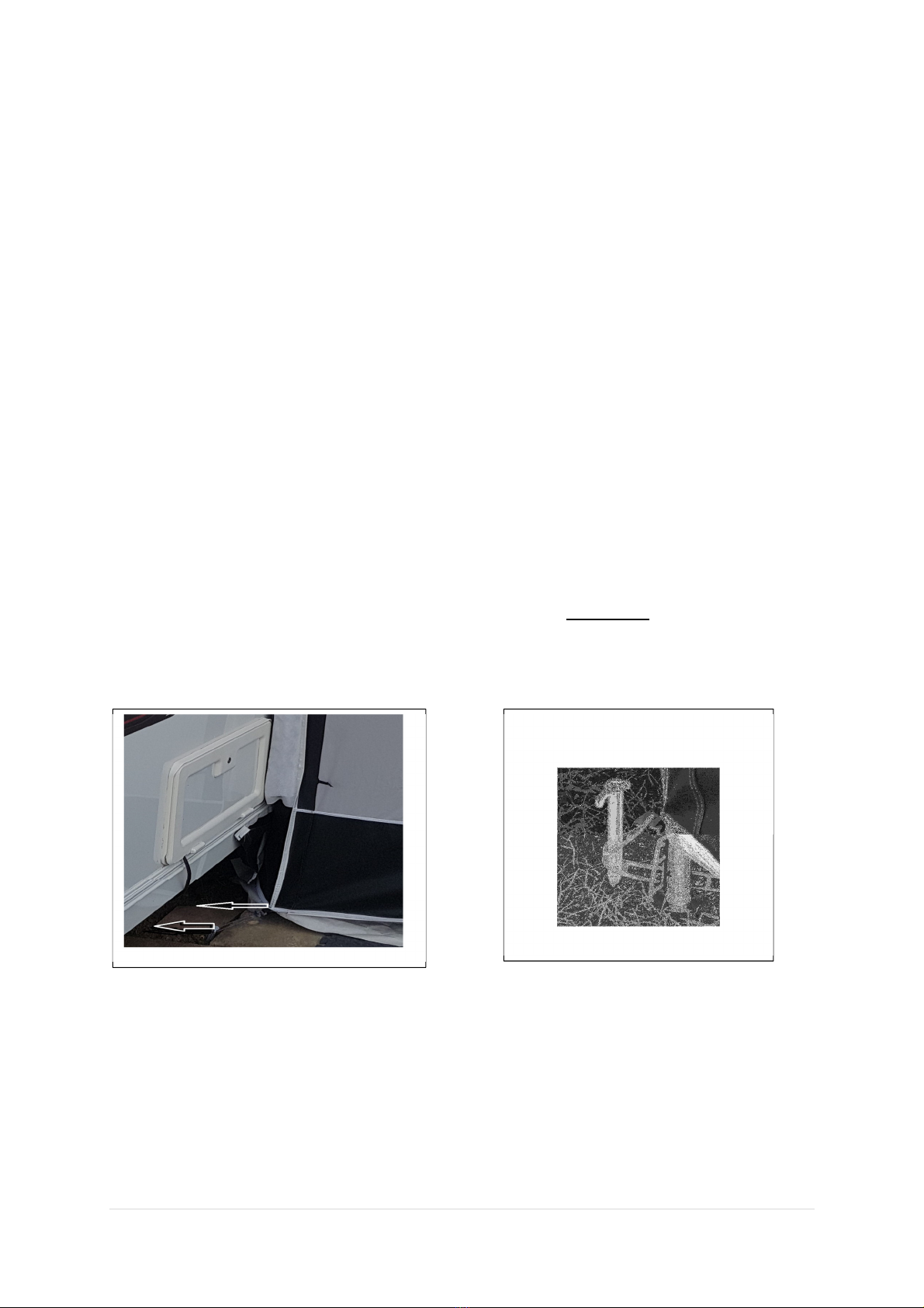
Fit pegging ladders to the two back corners of the awning on the clips provided. There are two
sewn-in clips at this point. One is for pegging the awning to the ground and the other is for the foot
of the back pole (see notes on next page). Please make sure you peg as shown in diagram 1 and pull
the side panels with the foam packers as close to the caravan wall as possible, ensuring both are
vertical and flush. To help get a secure fit, peg the ladder slightly nderneath the caravan as shown
below.
Make sure at this point that the side door zips are both fully closed. Connect the black clip and
buckle arrangement together (this is found at the top next to the caravan) and adjust the buckle to
ensure the piping fitment of both the main base unit and the side panel are fully closed together.
Diagram 1
Diagram 2
3 | P a g e
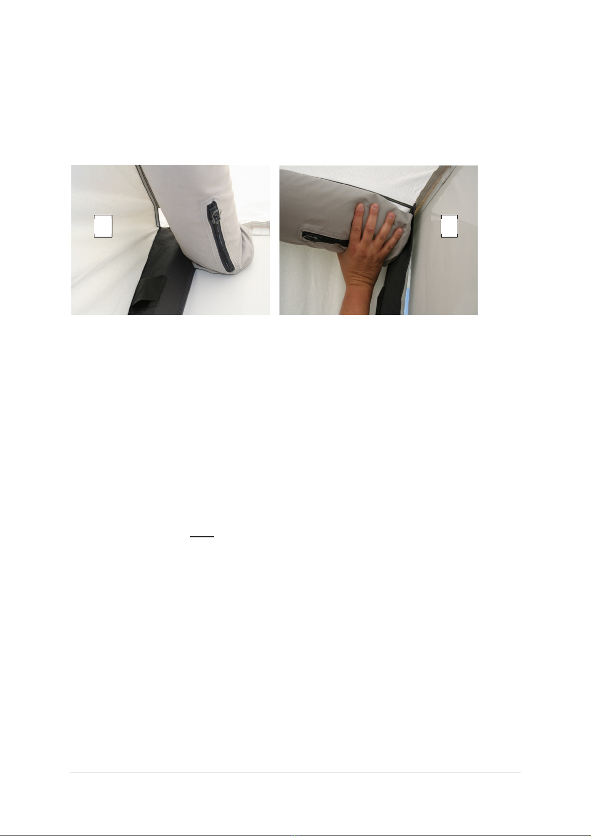
ssemble the two Easy lloy “back poles” and fit the blanked end of the pole into the small black
pocket on the “packer”, located down the side of the caravan. Ensure that the packer itself is lying
flat against the caravan. The AiR t be m st be f lly into the top corner of the awning with the
packer lying flat between the caravan and AiR t be and the Velcro strips art the very top attached.
s shown in the photos below.
Incorrect position of ir Beam Correct position of ir Beam
IMPORTANT The foot of the “back pole” should be inserted into a pegging ladder at the base of the
packer. By doing this, you will get much better tension and a much better overall appearance of the
awning. s mentioned previously, there are 2 sewn-in ladder clips at this point. One to peg to the
ground with and the other for this pole. See diagram 2 on page 2. pply a small amount of vertical
tension to the pole from the ground upwards, to hold the packer against the caravan. (Too much
tension here will damage the pocket into which the pole is fitted. lease make sure the pole is not
extended further than the height of the pocket). Tie the pole in position with the ties provided.
t this point you can peg the two front corners of the awning. Before pegging you must a) ensure
that the canvas footprint is square to the caravan and taut along the bottom of all three sides and, b)
you peg, if possible on the same “ladder” position you used when pegging at the back next to the
caravan. Ladder “Rung” number 3 is ideal. Rungs 1 and 6 are for emergency use only.
There are 2 pump adapters supplied. The larger for the electric pump, the smaller for the foot pump.
These should be fitted to each pump hose. You may have to remove any already fitted adapter from
the hose ensuring you leave on the fitting that connects to the pump. (It is easier to simply cut off
the unwanted fitting.)
Screw the valve inflation adapter into the chosen valve ensuring that it is not cross threaded. (This
should only require between 0.5 and 1.0 clockwise turn to seal sufficiently.)
If using the electric pump, set the dial located on the front of the pump body to “30”. This should
deliver a final pressure of approx. 0.3Bar, the working pressure. The pump will automatically stop at
the pre-set pressure. Should the pump not automatically stop, it is likely that a valve has been left
“locked open” (see paragraph 3 on page 1) or the adapter is cross threaded. (The pump is capable of
delivering up to 1.0Bar which is too high, so please ensure the dial is set correctly).
X

4 | P a g e
ttach the crocodile clips to the 12 volt power source, either on your caravan or car battery,
ensuring correct polarity. Firmly press the button on the pump and the pump should start. (The
switch is waterproofed and may require firm or repeated pressure until it starts up.)
When using the foot operated pump, connect in the same way. (5 ltrs. of air is delivered with each
press and the pump is only capable of inflating to a maximum of 0. Bar.)
During the inflation procedure, you will need to assist the inflation beams by lifting “GENTLY” on
the canvas from the centre and each front corner, with the storm strap fitments on the canvas.
IMPORTANT If sing the electric p mp yo will notice it will stop momentarily and immediately re-
start with a change in the so nd of the p mp. This is the change from turbine to piston pumping
mode and it is at this point yo sho ld assist the canvas.
Once fully inflated, check the awning’s position relative to the caravan. Make sure the awning is both
square to the caravan and that the base of the awning, along each side and across the front, are
taut. (If you chose to do this earlier check the fit and alignment and, if necessary, re-peg.)
Should there be any diagonal creases within the awning roof section, you should adjust the pegging
at the front corners. This should see the diagonal creases disappear.
Once happy with the general fit of the awning, attach the sliding pegging clips to the small piping
fitment on all the panels. Fit the remaining pegging ladders to both the sliding and fitted clips and
peg all round with the large grey plastic pegs. We strongly recommend that yo cross peg at each
doorway to reduce pressure on the zip and stop the sliders “riding up” and opening. (Keep the pump
attached for the moment in case it is necessary to partially deflate and re-inflate)
At this point of assembly yo may decide to fit an extension(s). If you are not fitting an extension
then proceed immediately to the section marked (*).
We recommend that the pressure be reduced on the “main” base unit of the awning, sufficient to
ensure the unit can stand unassisted but low enough to allow easy access to the “joining” zippers.
The left hand facing side panel should now be removed to allow a connection between the main unit
and the chosen extension. IMPORTANT It is vital that the side panel be separated from the main
nit by nzipping from the top of the awning and disconnecting the zippers at the gro nd level
end. (This removed side panel will then be re-fitted to the extension once the extension has been
fitted to the main unit. If using Modul-AiR in a “full awning” configuration with a front closure unit,
this side panel becomes redundant).
Thread the chosen extension into the awning channel from the front of the caravan until it meets
the main base unit. Connect the joining zippers on both the extension and main base unit.
IMPORTANT This connection m st be made at the gro nd level end, then slide the zipper’s slider
all the way to the other end of the zipper as far as it will go. (It is vital the zipper is fully closed at the
top next to the caravan).
Connect the black clip and buckle arrangement together (this is found at the top next to the caravan)
and adjust the buckle to ensure the piping fitment of both the main base unit and the extension are
fully closed together.
Repeat the above for each extension you wish to add. If using only one extension the side panel
should now be re-fitted again making sure the zipper connection is made at ground level. The black
clip and buckle arrangement will also need to be connected.

5 | P a g e
From inside the awning you will see that the extensions “cross beam” inflation tube is fitted with
Velcro on the end. This should be attached to the opposing Velcro found on the side of the main
inflation beams. The connection here can be re-adjusted at any time following inflation.
Once all required extensions are in place, repeat the first part of the pegging process as you did on
the main unit, re-inflate the main unit and then inflate each extension beginning with the extension
closest to the main unit. (Pressures required are the same for both the main unit and the
extensions.)
Once happy with the general fit of the awning, attach the “sliding” pegging clips to the small piping
fitment on all the extension panels. Fit the remaining pegging ladders to both the sliding and fitted
clips and peg all round with the large grey plastic pegs. We strongly recommend that yo cross peg
at each doorway to reduce pressure on the zip and stop the sliders “riding up” and opening. (Keep
the pump attached for the moment in case it is necessary to partially deflate and re-inflate)
(*) Using the “mushroom” headed pegs, secure the mud-wall inside the awning, pushing the pegs
through the eyelets within the mud-wall material.
ssemble the curtain rods by fitting the black plastic “rod ends” one to each tube. The rod ends have
2 internal diameters, the first for the thicker of the rods, the second for the thinner. Once pushed
home (they are a tight fit), they will remain in place and there is no need to remove them after use.
Slide the correct size curtain onto one of the thicker rods (one to each rod for the side panel
windows) then insert the thinner rod into it and fit the rod ends into the black loops found at the top
corners of each window. “Tie Backs” are provided at the bottom of each window. Please refer to the
curtain configuration sheet within the pack, to establish which curtains go where.
On the front windows, attach the elastic/toggle to the black loops at the bottom corner of each
window. This will ensure that when the curtains are drawn they are held against the front panel of
the awning.
Should there be the possibility of adverse weather conditions, we recommend that you use the
“storm straps” fitted to the front of the awning. These simply click into the fitted buckles and are
then pegged out at an appropriate angle and adjusted at the buckle. (Do not over-tension these as
they may adversely affect the overall shape of the awning.)
On a new awning we would advise starting the pump again to ensure any movement caused by the
bladder settling, has not dropped the pressure slightly. (This pumping cycle may not even start or
may last only a few seconds.)
There is an elasticated draw string fitted within the outer edges of the base unit and on one side of
each extension. This draw string should be tensioned from the bottom of the awning on both the
outer edges and where any extensions are fitted and can be locked by means of the toggle lock
attached to the draw string. The tension applied can vary from unit to unit but would recommend
that at least one metre of the draw string is pulled through but not more than two metres. This will
ensure the joining zips are fully protected from the weather. (Do not forget to de-tension these draw
strings before taking the awning down.)
That’s it, enjoy!

6 | P a g e
DEFLATION
When taking the awning down, open the dust covers and remove the pump from all valves. Deflate
by pushing in the valve insert with your finger at the same time twisting the insert anti- clockwise,
which will lock the valve open. We recommend that this is done with all the valves to ensure as
much air as possible leaves the bladders for packing. Then simply reverse the order of the
instructions. When packing the awning away lay the canvas outside down, on top of your ground
sheet, on the ground. Fold the side panels into the roof but leave the front panels flat on the floor.
Fold the roof and front lengthways into two (into three for the 90 model) and roll up the canvas
from the roof end. s the valves are still open this will allow all air pockets to empty and reduce the
size of the packed awning. (Once rolled, it is good practice to unroll and re-roll the canvas to expel
more air.) This process can be made much easier if the side and front panels are removed before
deflation. It is however important they are re-fitted prior to putting the awning up again to ensure
the correct “footprint” is achieved before inflation.
IMPORTANT
new awning will require time to “weather”. s such you may experience some leaking through the
sewn seams until such time as the thread within the stitch holes has had the opportunity to swell
and fill out the stitch holes. There is no time limitation on when this is achieved but 3 or 4 good
soakings should suffice. The most important part of the weathering process, is the awning drying
out thoroughly before the next rain fall. Light rain is ideal for this purpose but if subjected to very
heavy rain when new, considerable leaking may be experienced!
On first inflation, the air bladders within the awning may need to adjust themselves to “comfort” fit.
Should you see any areas where the inflation beams have a slightly twisted, misaligned or “lumpy”
appearance, it is advisable to deflate the beams and then re-inflate. Each time the awning is inflated
any “lumpy” areas will eventually disappear once the bladder has settled within the confines of its
carrier.
Please do not attempt to open any of the containment zips in the air beams at any time. There are
no c stomer serviceable parts contained within those zips and opening them witho t an express
written instr ction from Bradcot will invalidate yo r g arantee. These zips are fitted with a “ se
once only” sec rity tag and sho ld not be removed.
The air beams adjacent to the caravan are not attached to the main canvas for a small distance. This
is deliberate to allow a comfortable fit against the caravan.
The pressure within the beams is temperature sensitive. 20c degree change in ambient
temperature can be coped with by the beams. However, if you erected the awning on a hot day it is
advisable to re-pressurise the beams once the ambient temperature has dropped. This will ensure
the unit remains at working pressure when cold.
s with all marine grade (serviceable) valves some loss of air pressure and volume is inevitable
through the valve. s such we recommend that the foot operated pump is available on hand with
which to “top up”. If the beams are easily depressed with a hand grip you should top up from any
one of the valves. twice daily check is recommended.
The electric pump can draw considerable amps in piston mode. s such we do not recommend
extending its power lead. Connection must be made to a suitable 12 volt battery with the crocodile
clips. Do not attempt to fit a “cigar lighter” type plug to the lead. This co ld damage the cars wiring.

7 | P a g e
REGISTERING YOUR NEW AWNING
ll of our inflatable awnings come with a life time guarantee on the bladders and valves. Because of
this we strongly recommend that you keep your original receipt (preferably something with your
name and/or address on) along with this paperwork, as it will be needed in the event of a claim.
Please also register your new awning immediately on our website at www.bradcot-awnings.co. k.
(This service is available “on-line” only and is not available by telephone.) Registration ensures that
we have an accurate record of the units you have bought and that your details will be easily
accessed should you feel the need to contact us in the future. We can guarantee, you won’t
remember the size of the units 5 years down the line!
In the unlikely event you have any component parts missing from your package, please contact us
immediately with your order details at info@bradcot-awnings.co.uk. ny shortages or damage must
be reported with 7 days of you receiving the product to avoid any charges for the supply.
We wo ld also strongly recommend that yo complete the form on yo r Awning Ga rantee card
and keep for yo r own records along with yo r awning receipt and any original doc ments.
GENERAL CARE OF YOUR NEW AWNING
The following are some general “dos and don’ts” to help get long and faithful service from your
awning;
Do: Open out your awning at home, make yourself familiar with the contents and check for
anything missing using the packing check sheet attached.
Do: Ensure the awning rail on your caravan is clean and smooth running.
Do: Dry the awning fully within 7 days of taking it down.
Do: Wipe each pole with a dry cloth after the frame has been dismantled.
Do: Ventilate your awning as much as possible, or condensation can form on the underside of
the roof, which is often mistaken for leakage.
Do: Be aware that some seams may leak until “weathering” is complete. More information on
weathering and condensation can be found at www.bradcot-awnings.co.uk
Do: Clean all mud etc from the mudskirt and splashwall after each use.
Do: Wipe your awning with a clean cloth or brush with clean tepid water. Further cleaning
advice can be found at www.bradcot-awnings.co.uk
Do: Contact our customer services department for any advice on info@bradcot-awnings.co.uk
Don’t: If possible, pack your awning away whilst still wet or damp.
Don’t: Clean the awning with any type of detergent.
Don’t: Use any aerosol sprays on or near the canvas parts.
Don’t: Use any awning “tie-down” kit, other than that available from Bradcot UK. These can be
purchased via our website.
Don’t: Use any electrical appliances inside the awning. This is a fire hazard.
Don’t: Cook with a naked flame inside the awning.
Don’t: ttempt to erect the awning in windy conditions.
Don’t: Leave your awning unattended for long periods. You will be required to top up with air as
and when necessary.

8 | P a g e
MODUL-AiR PACKING CHECK LIST
(V-1.9)
The following is a list of contents that should be found within the “MODUL-AiR” AWNING BOX.
MAIN AWNING CANVAS PACK
GROUND PEG PACK (to include large and small pegs)
STORM STRAPS (Modul- iR 260 and 330 x 3. Modul- iR 390 x 4)
DRAUGHT CLOTH PACK (includes draught cloth, wheel arch, channel, Velcro)
PEGGING LADDER PACK
SLIDING “LADDER CLIP” PACK
CURTAIN PACK
CURTAIN ELASTIC PACK
CURTAIN ROD PACK (includes rods, rod end plugs (1 size) and Instructions)
INFLATION PACK (pump adapters for Modul- iR 260, 330 and 390 base units only)
INSTRUCTION PACK
MANUAL INFLATION FOOT PUMP (Modul- iR 260, 330 and 390 base units only)
BACK SUPPORT POLES x 2 (Modul- iR 260, 330 and 390 base units only)
BAG FOR SUPPORT POLES (Modul- iR 260, 330 and 390 base units only)
MODUL-AiR EXTENSION AND FRONT ENCLOSURE PACKING CHECK LIST
The following is a list of contents that should be found within the “EXTENSION” or “FRONT
CLOSURE” BOX.
GROUND PEG PACK (to include large and small pegs)
STORM STRAP X 1
DRAUGHT CLOTH PACK
PEGGING LADDER PACK
SLIDING “LADDER CLIP” PACK
CURTAIN PACK
CURTAIN ELASTIC PACK
CURTAIN ROD PACK (includes rods, rod end plugs (1 size) and instructions)
INSTRUCTION PACK
INSTRUCTION MANUAL UPDATES
Please check on line at www.bradcot-awnings.co.uk for any updated version of these instructions.
These are checked regularly and posted on line for you to download at your convenience.
Table of contents
Popular Tent manuals by other brands


Coleman
Coleman 1417721 Setup instructions

ShelterLogic
ShelterLogic Shed-in-a-Box 70483 manual

Royal garden
Royal garden GQC00229A Assembly instructions

may SCHIRM-SYSTEME
may SCHIRM-SYSTEME Albatros installation instructions

Wanderer
Wanderer Magnitude Assembly instructions

ABSCO SHEDS
ABSCO SHEDS CG34552N2 manual


