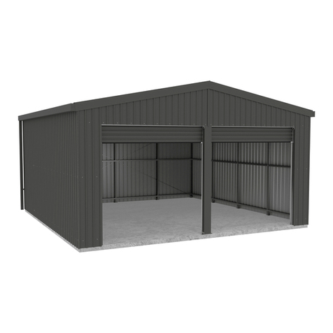
ABSCO SHEDS GCPDN2 User manual

Absco Industries Assembly Instruction Manual
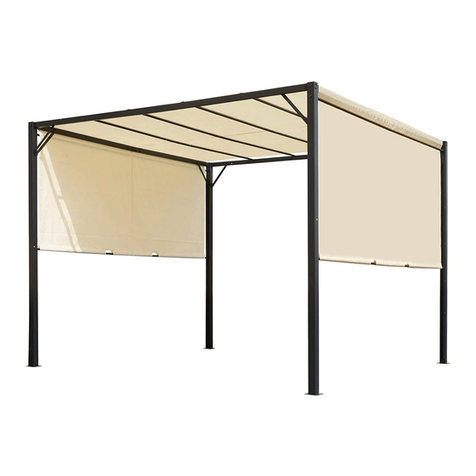
ABSCO GABLE CARPORT
MODEL: GCPDN2
6.0mW x 6.0mD x 2.98mH
Model: GCPDN2 8/06/23 1
AU: 1800 029 701
N Z: 0800 466 444
www.abscosheds.com.au
DOWNLOAD
OUR APP FOR
ASSEMBLY
VIDEOS
PLEASE LEAVE A REVIEW
Tell us about your experience!
Visit www.abscosheds.com.au/review
6445 mm
6345 mm
For construction in non-cyclonic areas
Wind rating: N2 as per AS4055-2021
If you require a higher wind rating please contact us:
Concrete footings & optional slab detailed in
engineering drawings pg 16,17

Absco Industries Assembly Instruction Manual
ABSCO GABLE CARPORT
MODEL: GCPDN2
6.0mW x 6.0mD x 2.98mH
Model: GCPDN2 8/06/23 2
Site Preparation
• Local council approval must be obtained prior
to construction of the carport. Once you have
selected your site you will need to create
and lodge a site plan to your local council or
certifier. You will also have to attach a copy of
the engineering drawings at the back of these
instructions to your site plan.
• The site for the carport must be level, refer
to concrete and foundation notes on the
engineering drawing.
General Instructions
• Beforecommencinganyassembly,readthrough
these instructions and engineers drawings in
detail to gain a thorough understanding of
assembly methods and associated details.
• Some components have been pre-punched.
Some 10mm holes will still have to be drilled.
It may be easier to drill a small pilot hole first.
• Measure, and check off all components using
the parts lists on the following pages prior to
commencement. To prevent damage in transit,
some components may be packed inside
others, almost hidden. Carefully examine
inside each component to ensure that you
have located every item. If a discrepancy is
found, contact Absco Industries immediately.
• Don’t cut any components to a different size
unless instructed.
• Three types of tek screws are supplied, take
care to use the right type for the step.
Safety Notes
• The assembly of this product requires some
lifting of heavy objects. Two person lifts are
required.
• Some parts have sharp edges and/or corners.
The use of gloves and safety shoes is highly
recommended. Pay attention to where these
parts can be safely handled, and plan the
handling of these parts before working with
them.
• Drilling sheet metal produces small metal
shavings the use of safety glasses and the
periodic clearing of these shavings throughout
the build is recommended.
• Use the appropriate personal protective
equipment for any tool used during the
assembly.
Tools Required
Some tools required include:
BEFORE STARTING ASSEMBLY
• Electric drill with chuck
• 3 and 10 mm drill bits
• Hammer drill
• 12 mm masonry drill bit
• Mallet
• ‘G’ clamps
• Tape measure
• Socket set
• 17 mm spanner / shifter
• Spirit level
• Water proof sealant (silicone)
• 1.8m ladder
• PVC solvent welding cement.
Absco Industries Assembly Instruction Manual
ABSCO GABLE CARPORT
MODEL: GCPDN2
6.0mW x 6.0mD x 2.98mH
Model: GCPDN2 8/06/23 3
QTY DESCRIPTION PART # CHK
6
TRUSS
TOP CHORD
2946 mm
C2946
6
TRUSS
BOTTOM CHORD
2910 mm
S2910
6
TRUSS
CENTRE VERTICAL
525 mm
M0525
6
TRUSS
MID VERTICAL
337 mm
P0337
6
TRUSS
OUTER VERTICAL
170 mm
P0170
6
TRUSS
INNER DIAGONAL
976 mm
R0976
QTY DESCRIPTION PART # CHK
6
TRUSS
OUTER DIAGONAL
958 mm
S0958
6
TRUSS
OUTER INFILL
650 mm
C0650
12
TRUSS
INNER INFILL
850 mm
C0850
12 PURLIN
2960 mm C2960
6
PURLIN
JOINER
200 mm
C0200
QTY DESCRIPTION PART # CHK
4
OUTER
EDGE BEAM
1585 mm
ZACO
117
2
OUTER
EDGE BEAM
2750 mm
ZACO
196
4GUTTER
3030 mm TR22
4
BARGE
FLASHING
3030 mm
TR06
16 STEEL SHEET
3030 mm 303
QTY DESCRIPTION PART # CHK
6
INNER
EDGE BEAM
1973 mm
ZACO
118
4COLUMN
75 x 75 x 2250 mm
COL
04
2DOWNPIPE
100 x 75 mm TR10
2
RIDGE
CAPPING
3030 mm
TR08
8STEEL SHEET
680 mm 068
C S
M C
P C
S C
P C
R
FRAME PACK
LARGE ITEMS

Absco Industries Assembly Instruction Manual
ABSCO GABLE CARPORT
MODEL: GCPDN2
6.0mW x 6.0mD x 2.98mH
Model: GCPDN2 8/06/23 4
QTY DESCRIPTION PART # CHK
2
DOWNPIPE
DROP
100 x 75 mm
RWG
18
4
DOWNPIPE
STRAP
450 x 20 mm
TR29
3
TRUSS TOP
JOINER PLATE
160 x 80
ZACO
201
18 PURLIN
BRACKET
BKT
11
4EDGE BEAM
END CAP
ZACO
155
1ROOF
STRAP
FAST
041
8ANGLE BRACE
40 x 30 x 620 mm
ZACO
232
4ANGLE BRACE
40 x 40 x 700 mm
ZACO
122
QTY DESCRIPTION PART # CHK
16 GUTTER
BRACKET
RWG
06
4GUTTER
END STOP TR25
6
TRUSS SIDE
JOINER PLATE
70 x 450 mm
ZACO
181
10 MULTIPURPOSE
BRACKET (MPB)
BKT
17
16
COLUMN BASE
BRACKET
12 mm HOLE
BKT
03
3FLY BRACE
40 x 40 x 850 mm
ZACO
125
6FLY BRACE
40 x 40 x 570 mm
ZACO
124
6FLY BRACE
40 x 40 x 320 mm
ZACO
123
COMPONENT LIST
FITTINGS PACK
QTY DESCRIPTION PART # CHK
1PHILLIPS HD
DRIVER BIT
FAST
038
16
BOLT
M10 x 20 mm
& NUT
FAST
018
16 DYNABOLT
12 x 60 mm
FAST
016
1000
HEX HD
TEK SCREW
10-16x16mm
FAST
035
400
HEX HD
TEK SCREW W/ NEO
WASHER 10-16x16mm
FAST
033
QTY DESCRIPTION PART # CHK
1HEX HD
DRIVER BIT
FAST
023
8
BOLT
M10 x 100 mm
& NUT
FAST
099
40 M10 WASHER FAST
017
200 WAFER HD
TEK SCREW
FAST
014
50 POP RIVETS FAST
009

Absco Industries Assembly Instruction Manual
ABSCO GABLE CARPORT
MODEL: GCPDN2
6.0mW x 6.0mD x 2.98mH
Model: GCPDN2 8/06/23 5
1. Footings (Piers)
Prepare site and mark out
positions as per the engineering
drawings.
Dig footings then box surrounds
to form a level flat concrete
surface for fixing framework to.
TIP: *It is recommended that the
concrete should be boxed 100
mm above ground level to allow
for a future slab.
2. Slab - optional
Prepare footings as noted in A.
Pour a perfectly level slab to
the dimensions specified in the
engineering drawings.
Alternatively you may prefer
the slab to finish flush with the
outside of the footings.
The slab will be 100 mm thick,
reinforced with F72 mesh, laid 30
mm from the top. 50 mm thick
sand bedding on a water proof
membrane
No edge thickening is required
apart from the footings as
detailed.
FOUNDATIONS
GROUND
F72 mesh with
30 mm of top
cover
waterproof
membrane
50 mm sand
bedding
SLAB
100
600
PAD FOOTING
600x600x600 600
100*
12mm
dynabolts
GROUND
Please refer to engineering drawings that specify overall footings layout, slab and post dimensions.

Absco Industries Assembly Instruction Manual
ABSCO GABLE CARPORT
MODEL: GCPDN2
6.0mW x 6.0mD x 2.98mH
Model: GCPDN2 8/06/23 6
Guide for Connecting Frame Sections
Absco sheds’ frame assemblies are supplied with
10-16x16 self drilling wafer head phillips drive tek
screws
The wafer head minimises distortion to the sheet
cladding once it is fitted to the frame
Ensure that driver bits used to fasten these screws
is phillips drive, as similar alternatives (EG. Pozi
drive) increases the risk of stripping the head of
these screws.
Some holes are pre-punched in Absco sheds’ frame
sections, however the wide range of positions that
most fasteners are required for means that the
remainder have to be drilled as per the connection
being made
A 3mm drill bit is supplied for pre-drilling holes
where self drilling screws may be more difficult to
establish holes with (EG. Fitment of purlin brackets).
Absco sheds’ frame sections are manufactured
from light gauge steel, enabling for the notched
ends or lengths of one frame section to be spread
over the sides of another frame section, boxed
frame section or H-section.
Absco sheds’ frame sections are designed to nest
into one another to create boxed frame sections
Boxed frame sections are only required in some
parts of the entire frame assembly
Boxed frame sections are fastened together using
the fast014 tek screws supplied at 300mm centres
(unless otherwise stated) along the length of each
boxed frame section.
Some connections are designed to fasten more than two parts together. Connections may also not
feature a defined alignment or physical stop.
For these reasons, focus on arranging all parts of a frame assembly or subassembly together (to
the overall sizes and check measurements nominated) using minimal screws. This allows for easier
adjustment to various connections which may be necessary to achieve the overall dimensions and
check measurements that are nominated.
Fit the remaining screws once the frame assembly or subassembly is assembled as per the overall
dimensions and check measurements that are nominated
Boxing Frame Sections
A
A
B
B
HIGH SIDE A
HIGH SIDE B
LOW SIDE B
LOW SIDE A FAST014
FAST014
HIGH SIDE
HIGH SIDE
(PRINT)
(PRINT)
LOW SIDE
LOW SIDE

Absco Industries Assembly Instruction Manual
ABSCO GABLE CARPORT
MODEL: GCPDN2
6.0mW x 6.0mD x 2.98mH
Model: GCPDN2 8/06/23 7
1. Take the bottom chord S2910
and box-in the infill pieces at the
distance specified. Fasten with
wafer head tek screws.
2. Test fit in the rest of the frame
members.
Check the verticals are spaced
along the bottom chord at 970
mm as shown at the bottom of
the page.
Check the height at the centre
vertical M0525 and make sure it
is perpendicular to the bottom
chord.
3. Fasten all frame pieces with
two wafer head tek screws per
tab.
Use six screws per side at the
end where the top chord fits
inside the bottom chord.
4. Take three purlin brackets
BKT11 and mount them to the
top chord at the dimensions
specified.
Orientate them as shown and
fasten with four tek screws into
the top chord.
TRUSS ASSEMBLY
290 mm 60 mm 120 mm 90 mm
P0337
M0525
P0170
S0958
R0976
C2946
End of
S2910 with
cut out
970
975 975 916 80
970 970
540
CLCL
S2910
C0650 C0850 C0850
P0337
P0170
S0958
C2946
80
- Repeat these steps until you have 6 -

Absco Industries Assembly Instruction Manual
ABSCO GABLE CARPORT
MODEL: GCPDN2
6.0mW x 6.0mD x 2.98mH
Model: GCPDN2 8/06/23 8
5. Butt two half truss assemblies
together to make a single
5820mm wide truss.
Use a string line to check the
bottom chords are straight.
6. Join both top chords with the
top joiner plate ZACO201.
Fix one side with 4 wafer head
tek screws, then bend down the
other and fix with 4 more screws.
7. Next each side will need a
larger joining plate ZACO181
and 20 screws per side.
Repeat these steps until you
have three completed 5.8m
trusses.
1. Layout the framing pieces as
shown.
2. Box the C0200 halfway into
one end of a C2960 and fasten
with 2 wafer head tek screws per
side.
3. Box the other C2960 in and
fasten as before.
Repeat these steps until you
have six completed purlins.
TRUSS ASSEMBLY
PURLIN ASSEMBLY
5920 mm
ZACO181
ZACO201
- This completes the truss assembly -
- This completes the purlin assembly -
C2950 C2950
C0200

Absco Industries Assembly Instruction Manual
ABSCO GABLE CARPORT
MODEL: GCPDN2
6.0mW x 6.0mD x 2.98mH
Model: GCPDN2 8/06/23 9
1. Arrange the six edge beam
pieces as shown on the left.
2. Nest the Inner edge beams
inside the outers.
Check for straightness.
When happy with the fit and the
assembled length is 5920 mm
proceed to fastening.
Fasten all with tek screws at 300
centres.
TIP: The top side of the beam
needs wafer head teks. The
underside of the beam can be
hex head tek screws
3. Remove all screws for the
two outer edge beam pieces
ZACO117.
This will allow access to fit the
columns later.
Repeat these steps again we
need two edge beams.
EDGE BEAM
ZACO196
ZACO117
ZACO118 ZACO118 ZACO118
ZACO117
Inner edge beams are 1973 mm
Outer edge beams
2750 mm
1585 mm 1585 mm
5920 mm
OuterInner
- That completes the side beam assembly -

Absco Industries Assembly Instruction Manual
ABSCO GABLE CARPORT
MODEL: GCPDN2
6.0mW x 6.0mD x 2.98mH
Model: GCPDN2 8/06/23 10
1. Take a COL04 and a BKT03.
Align the bottom edge of the
bracket with the end of the post.
Using the two holes in the
bracket as a template mark and
drill out with a 10mm drill bit.
TIP: Predrilling can make this
step easier.
2. Repeat to all four faces of the
column.
3. Place a BKT03 and fasten with
a pair of M10 x 20mm bolts, nuts
and washers.
Poke the bolt through from the
inside of the post and use a nut
and washer on the outside.
Turn over and repeat for the
opposite side.
4. Fasten the remain two BKT03
brackets using a pair of M10 x
100mm bolts, nuts and washers.
These are simple through-bolts.
5. Take a BKT17, align the edge
with the top end of the post
and fasten with six hex head tek
screws.
Repeat these steps until you
have four columns.
POSTS
COL04
BKT03
BKT17
- That completes the post assembly -
Flush

Absco Industries Assembly Instruction Manual
ABSCO GABLE CARPORT
MODEL: GCPDN2
6.0mW x 6.0mD x 2.98mH
Model: GCPDN2 8/06/23 11
3
80
80
40
NOTE: Throughout frame construction the structure will be unstable until construction is fully
completed. Make sure during construction framework is braced using rope or timber props to
stabilise and prevent twisting or collapse. Assemblies are too heavy for 1 person to lift unaided.
Safely lift a truss and place on
top of a pair of posts.
Make sure the outside of post
and end of truss are flush.
Fasten with 6 hex head tek
screws in the MPB and into the
truss.
Do this for both end trusses.
POSTS
FITTING END TRUSS TO POSTS
FITTING EDGE BEAM
Truss
Flush
Post
1. Safely lift and align the edge
beam as shown. It has to sit 80
mm below the post as shown.
Fasten to the column with 10 hex
head tek screws.
2. After both ends of the beam
are secured, refit the outer
pieces of edge beam ZACO117.
Remember wafer head teks for
the top side.
3. Close both ends of the edge
beam with an end cap ZACO155
and two tek screws.
1 2
3
1. Place the posts on the
foundation, use the dimensions
shown to confirm correct
placement.
Position each column with the
top bracket to the centre.
Mark out the base bracket hole
positions on the concrete.
Using a 12mm masonry drill bit,
drill the anchor holes and secure.
Please refer to
engineering drawings
that specify concrete
footings / slab and post
distances.
5670
5770
5920
FRONT
5820

Absco Industries Assembly Instruction Manual
ABSCO GABLE CARPORT
MODEL: GCPDN2
6.0mW x 6.0mD x 2.98mH
Model: GCPDN2 8/06/23 12
1. Centre Truss
Secure centre truss to edge
beams.
Measure in 2960 mm from one
end of the edge beam to mark
the centreline of the truss.
Secure three MPB to each side
as shown with 6 screws. Truss
must sit 80 mm up from the
underside of the edge beam.
Repeat for other beam then
safely lift truss into position and
secure with hex head tek screws.
NOTE: You will have to remove
wafer head tek screws where
they interfere with the MPBs.
2. Post Angle Braces
• Use two ZACO232 angle
braces to sandwich post
and truss. Fasten with 6 tek
screws per end. Make sure to
use wafer head tek screws to
outside of truss where sheet
will cover later.
• Position ZACO122 inside face
of edge beam to outside face
of post. Fasten with 3 hex
head tek screws per end.
NOTE: Ensure all posts are
vertical and make sure all braces
are fastened at 45 degrees.
3. Purlins
Place all six purlins on ‘uphill’
side of brackets and secure
with 4 hex head tek screws per
bracket.
ZACO232
ZACO122
Edge beam
End truss
80
CL
Edge beam
FRAME ASSEMBLY
End truss
Purlin
Purlin bracket
Refer to the engineering
drawings for further detail
such as screw fixing details.

Absco Industries Assembly Instruction Manual
ABSCO GABLE CARPORT
MODEL: GCPDN2
6.0mW x 6.0mD x 2.98mH
Model: GCPDN2 8/06/23 13
4. Fly Bracing
Fly bracing angles are positioned
at 45 degrees from the roof purlin
to the underside of each truss.
Each truss has the following fly
braces:
2x 320 mm ZACO123 for outer
purlins
2x 570 mm ZACO124 for mid
purlins
1x 850 mm ZACO125 for 1 centre
purlin
Notch one end of fly brace as
shown. This is to be bent to suit
and fit to the underside of truss
with two hex head tek screws.
Fly brace
Purlin
Truss underside
40
45 degrees
FRAME ASSEMBLY
ZACO123
ZACO124
ZACO124
ZACO125
ZACO123
5. Roof strapping
Lay roof strapping diagonally over
the top of the structure.
Secure one end with wafer head
tek screws into the edge beam
and clamp the other end in
position for now.
Use a spirit level and square
to check structure. Also check
dynabolts are fully tightened.
Tension the strapping to equalise
diagonal measurements. Secure
strapping to all trusses with a tek
screw where they overlap using
wafer head tek screws.

Absco Industries Assembly Instruction Manual
ABSCO GABLE CARPORT
MODEL: GCPDN2
6.0mW x 6.0mD x 2.98mH
Model: GCPDN2 8/06/23 14
Every pan
Every pan
2nd pan
2nd pan
20mm overhang
30 mm overhang min
Option. On the ground, lay out
the roof sheeting as if they were
on the frame already. Using a
piece of wood, as pictured, turn
up the pans of each sheet at the
end that’s going to be at the
ridge.
This will help prevent rainwater
entering the structure during
windy conditions.
1. When laying sheets:
• Give first sheet a 20mm
overhang of the end truss
• All sheets will overhang the
edge beam by min 30mm for
the gutters.
2. Use Hex head tek screw with
neoprene washer FAST035 at
every pan to top purlin and edge
beam.
Use one Hex head tek screw
with neoprene washer at every
second pan to the middle
purlins.
NOTE: Lift and fasten off a single
sheet at a time, this will mean
you can reach all screw positions
easily from a platform ladder.
Avoid walking on the roof so
sheeting is not damaged. If it is
necessary, walk only on the pans
at purlin locations after sheets
have been secured.
3. Repeat for the other side.
ROOF SHEETS
Hardwood with
25mm saw cut.
Slot roof sheet into
cut in wood and
bend

Absco Industries Assembly Instruction Manual
ABSCO GABLE CARPORT
MODEL: GCPDN2
6.0mW x 6.0mD x 2.98mH
Model: GCPDN2 8/06/23 15
1. Take a pair of 086 sheets and
overlap by 1 rib.
2. Check the ends are flush and
then make marks along the outer
edges as per the dimensions
shown.
3. Using a straight edge &
marker or chalk line mark the
angled line and carefully cut
using tin snips.
TIP: This cut edge will be
covered by barge flashing.
4. You’ll have four pieces.
That’s the sheets done for the
right side of a gable end.
Repeat the last steps, with the
angle going the other way, to
make the four left sheets.
5. Repeat steps until you have
enough pieces to sheet the front
and rear of the carport. 16 sheets
total.
Fitting sheets to framing.
Start with the centre-most sheets
and align the straight edge with
the bottom of the truss.
Every second pan fasten using a
hex head tek screw. Make sure
to not use the neoprene washers
here.
Avoid screw placement too close
to existing truss screws. These
can distort the sheeting.
GABLE SHEETS
600
80
340
340
086
086

Absco Industries Assembly Instruction Manual
ABSCO GABLE CARPORT
MODEL: GCPDN2
6.0mW x 6.0mD x 2.98mH
Model: GCPDN2 8/06/23 16
1. Attach end caps and join lengths
of gutter TR22, to match the length
of the edge beam by notching the
roller edge of one to allow the other
to slide into it.
Put silicone in the joint and then
use rivets, FAST009, to fasten the
sections together.
2. Repeat this for the other side.
3. Mark the rectangular cutout to suit
the downpipe drop RWG18 at the
end you select.
4. Remove material and fix RWG18
with silicone and rivets.
5. Mark a line 110mm down from the
top of the edge beam at both ends.
6. Run a string line between these
marks. This is a reference to align
the bottom position of the gutter
brackets, RWG06.
7. RWG06 are to be fixed to the
edge beam at either end and spaced
equally along the length.
You may adjust bracket height to
allow for a slight fall to the downpipe
position.
8. Fit gutter onto all brackets at
once. Push top of bracket into outer
roll of gutter and bend small support
arm down to hold the inner face.
9. Rivet the brackets to the gutter
through the bottom hole of each
bracket.
10. Fit downpipes to drops with
silicone and rivets. Secure to posts
with two downpipe straps bent to
suit.
Bend down the two arms
of the bracket over the
back edge of the gutter.
TR22
RWG06
RWG18
TR22
TR25
Cutout for downpipe
drop at back edge of
gutter.
GUTTER AND DOWNPIPE
FLASHING & CAPPING
TR06 Fit barge capping TR06 to the front and rear gables, fixing
where there is a purlin beneath it using tek screws with neo
washers.
Lay the ridge capping TR30 centrally on the roof, overlapping
the sections to make the same length as the roof sheeting.
Safely fix the capping to every second rib with neo teks.


Absco Industries Assembly Instruction Manual
ABSCO GABLE CARPORT
MODEL: GCPDN2
6.0mW x 6.0mD x 2.98mH
Model: GCPDN2 8/06/23 19
Absco Sheds Storage Guidelines
• Absco Sheds are designed to be weatherproof for normal weather conditions. In the event of extreme
weather conditions such as heavy rain, combined with high wind gusts, the ridge capping, sheeting joins,
screw fixings etc., may exhibit minor deformations which may allow some water entry. These areas should be
checked regularly to ensure that maximum strength and protection is maintained.
• Other weather conditions such as extreme heat and extreme cold, moist or dry air can influence the effects
of concrete floor moisture and/or condensation on the underside of the roof sheets.
• Absco Sheds and storage units are primarily used for storage of garden equipment such as lawnmowers,
wheelbarrows, garden tools etc. Storage items that might be adversely affected by any of the above conditions
may require additional protection such as being sealed or covered by plastic sheets and/or stacked above
the concrete floor on timber slats.
• Waterproof sealants may be used to offer further protection where required around joins and screw fixings,
as can rubber door seals and other products which are available from most hardware outlets.
• Placement of waterproof sealants (silicone) between the base of the shed and concrete slab is not
recommended, as this process can have a reverse effect, preventing excess water from escaping, resulting
with water accumulating and being trapped inside the shed.
• Absco accepts no responsibility for water entry, floor moisture, condensation or the condition of the Contents
inside your Absco steel building arising from any of the pre-mentioned weather conditions.
6-12 Activity St, Acacia Ridge QLD 4110
PO Box 119, Acacia Ridge QLD 4110
AU: 1800 029 701
N Z: 0800 466 444
www.abscosheds.com.au

Lifetime Warranty Statement
This warranty against defects is given by:
Absco Industries (ABN: 77 869 708 678)
Address: PO Box 119 Acacia Ridge QLD 4110
Ph: 1800 029 701
Fax: 07 3344 1191
Email: [email protected]
Date of issue: 18 November 2022
Details of Manufacturer’s Warranty
This product comes with a Lifetime structural warranty from the date of purchase. This warranty also
applies where there are missing or damaged parts identified in the parts list referred to in the instruction
kit within the product packaging.
Please ensure that you keep this warranty form in a safe place along with your proof of purchase. You can
register your warranty online http://abscosheds.com.au/warranty-details/ or complete the form on the
back of this document and mail it back to Absco, along with a copy of your proof of purchase.
The benefits of this warranty are in addition to your rights under the Australian Consumer Law (ACL) and
in particular, the guarantees implied under the ACL and any other rights and remedies of the consumer
under a similar law in relation to the goods and services to which this warranty relates.
Process of claiming warranty:
To make a claim under the warranty within the warranty period, you will need to contact the manufacturer
directly by phone or email:
Contact Number: 1800 029 701
You will be required to produce proof of purchase (this is at discretion of the manufacturer) at the time of
the claim.
The manufacturer bears the cost of replacing the products or spare parts or repairing the products and
reasonable direct expenses of claiming under this warranty:
Where parts are replaced, the manufacturer will bear the cost of sending the spare part and will endeavour
to deliver it to the customer’s nearest reseller within 20 working days for the customer to pick up. At such
time the customer may be required to return the alleged faulty parts.
Where assessment is required in case of replacing or repairing the product, the manufacturer will appoint
an assessor within 10 working days to identify the alleged defect. The manufacturer will bear the repair
costs by appointing a local tradesman. The manufacturer may choose to replace the product if the repair or
the cost of repair is not feasible. The replacement product will be available for collection from the nearest
reseller within 20 working days. The customer will bear the cost of assembly for the replacement product.
1
Table of contents
Other ABSCO SHEDS Tent manuals

ABSCO SHEDS
ABSCO SHEDS CPDW50 Installation guide

ABSCO SHEDS
ABSCO SHEDS CPSW33 User manual

ABSCO SHEDS
ABSCO SHEDS RG37601N2 User manual

ABSCO SHEDS
ABSCO SHEDS 3052UTK Installation guide

ABSCO SHEDS
ABSCO SHEDS CG34552N2 User manual

ABSCO SHEDS
ABSCO SHEDS CPSW50 Installation guide

ABSCO SHEDS
ABSCO SHEDS 3060HGK Installation guide

ABSCO SHEDS
ABSCO SHEDS CG56552N2 Installation guide

ABSCO SHEDS
ABSCO SHEDS RG60602N2 User manual

ABSCO SHEDS
ABSCO SHEDS CPSN2 User manual