manuals.online logo
Brands
  1. Home
  2. •
  3. Brands
  4. •
  5. ABSCO SHEDS
  6. •
  7. Tent
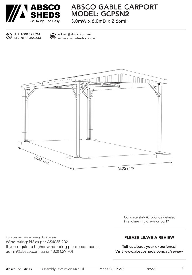
  8. •
  9. ABSCO SHEDS CG34552N2 User manual

ABSCO SHEDS CG34552N2 User manual

Absco Industries Assembly Instruction Manual
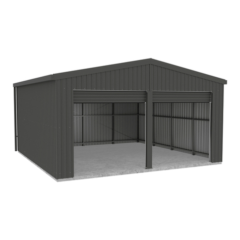
ABSCO COMPACT GARAGE
MODEL: CG34552N2
3.4m W x 5.5m D x 2.17m H
Model: CG34552N2 29/09/19 1
AU: 1800 029 701
N Z: 0800 466 444
[email protected]
www.abscosheds.com.au
For construction in non-cyclonic areas
Wind rating: N2 as per AS4055-2012.
If you require a higher wind rating please contact
us: [email protected] or 1800 029 701
Opening width: 2470mm
Opening height: 2180mm
Internal wall height: 2170mm
Download the Absco
Sheds Assembly App
for instructional videos
MANU FA CT URED
IN A US TR ALIA
SNAPTiTE
Assemb ly
3.4m x 5.5m x 2.17m
*The frame must be secured to a concrete slab
or footings, details of which are noted on the
attached engineering drawings. Brackets for
securing the frame to either a concrete slab or
footings are included in this kit. Anchors are not
included.
Local authority approval must be obtained prior
to construction. Once you have selected your
site, draw a site plan and lodge your application
together with a copy of the engineering plans
located at the back of these instructions.
Absco Industries Assembly Instruction Manual
ABSCO COMPACT GARAGE
MODEL: CG34552N2
3.4m W x 5.5m D x 2.17m H
Model: CG34552N2 29/09/19 2
Tools Required
Tools Recommended
Safety Notes
• Some parts and assemblies have sharp edges and/ or sharp corners.
• The use of gloves and safety shoes is highly recommended.
• Pay attention to where these parts can be handled most safely, and plan the handling of these
parts and assemblies prior to working with them.
• The assembly of this product requires drilling into sheet metal which produces small metal
shavings.
• Clearing of these shavings throughout the assembly process is highly recommended.
The assembly of this product requires some lifting of heavy assemblies
BUILDERS’
STRING
Absco Industries Assembly Instruction Manual
ABSCO COMPACT GARAGE
MODEL: CG34552N2
3.4m W x 5.5m D x 2.17m H
Model: CG34552N2 29/09/19 3
Steps To Construct Your Garage
Identification of parts ........................................................................... 4
Concrete slab/ footing details ............................................................ 9
Rear frame assembly ........................................................................... 11
Center frame assembly ....................................................................... 13
Front frame assembly .......................................................................... 15
Frame layout ........................................................................................ 17
Frame construction ............................................................................. 15
Fit roof purlins ..................................................................................... 20
Fit sheeting .......................................................................................... 21
Assemble & fit barn doors ................................................................. 24
Fit gutters & trim ................................................................................. 28
Engineering drawings ......................................................................... 30
1. Part numbers
As noted on page one, part numbers have been printed on most 80 x 40 channel sections and
sheeting. All other components have not been marked with part numbers, but can be identified by
their description, size and sketches provided on pages three, four and five of this instruction.
2. Personal Access Door (P.A. Door)
If you have selected the optional Personal Access Door, P.A. Door, There is an additional
instruction manual that is to be used in conjunction with this document.
3. All components pre-cut to size
Do not cut any components to a different size, unless it is clearly noted in this instruction to do
so. Dimensions in this assembly instruction are exact, where as dimensions noted on the engineering
plans are approximate. Double check that you have the correct component for the correct location.
4. Self drilling screws
Helpful Hints
10 x 16 Hex head tek screw for general use.
Phillips head tek screw - use on outside of
front framework to maintain a smooth sur-
face to surface to secure sheeting to.
The structure is assembled using these self drilling tek screws. All roof and wall sheets are pan
fixed. ie screw through the flat pan of the sheet into the framework.
Screw driver bits are included for use in your drill. Refer to the attached engineering drawings
for the quantity of screws required per connection.
10 x 16 Hex head tek screw with neoprene
washer for securing roof sheets to
framework.
Absco Industries Assembly Instruction Manual
ABSCO COMPACT GARAGE
MODEL: CG34552N2
3.4m W x 5.5m D x 2.17m H
Model: CG34552N2 29/09/19 4
5. Missing parts
To prevent damage in transit, some items are packed inside others. eg. some flashings may be
inside channel sections, other items may be packed inside gutters, some roof sheets packed on top,
some on the bottom etc. be very thorough when checking and locating all components.
6. Anchor sets not supplied (Hold down brackets are included)
Anchor sets are not supplied with this garage, but can be obtained from most hardware out-
lets. Anchors required for this garage are as follows;
11 Chemsets M10130 (10mm x 130mm Long)
2 M10 X 75 Dynabolts for P’ Door if applicable.
Note: M10 x 125 long dynabolts can be substituted for chemsets.
Frame Section Identification Guide
There are several types of frame section, each featuring a different combination of notches and/or
holes. Frame sections are coded with a letter representing the type of frame section, followed by the
length of the frame section in millimeters.
EG: C2960 = Straight cut both ends with overall length of 2960mm
C-TYPE - Straight cut at both ends M-TYPE - 45mm lip notch at both ends
J-TYPE - Straight cut at one end: 20mm tab notch with
holes at other end
K-TYPE - 20mm tab notch with holes at both ends
L-TYPE - Straight cut at one end: 45mm lip notch at other
end.
N-TYPE - Straight cut at one end: 45mm lip notch/20mm
tab notch with holes at other end
P-TYPE - 45mm lip notch/20mm tab notch with holes at
both ends.
R-TYPE - 45mm lip notch/20mm tab notch with holes at
one end: 90mm lip notch at other end.
S-TYPE - Variable notching and/or holes nominated in parts checklist
Absco Industries Assembly Instruction Manual
ABSCO COMPACT GARAGE
MODEL: CG34552N2
3.4m W x 5.5m D x 2.17m H
Model: CG34552N2 29/09/19 5
2 C2150
4
4
1
2
C0100
K0377
C2470
S1705
2 R0455
1 J0230
2 R1020
2 K0070
2
2
2
2
4
2
C2150
P1150
C2435
M1705
K1674
C0100
4
4
12
C2069
C1705
K1780
18 K1780
8
6
4
C2148
K1180
P1520
One leg of the channel section is 2mm shorter thatn the other leg to allow two channel sections to be
boxed together. Most framing requires only single sections of channel, with boxed sections located
only where noted in this instruction.
80mm x 40mm Galvanized Channel Framing Sections
SINGLE SECTION TWO SECTIONS
BOXED TOGETHER
80
38
40
PACK TYPE QTY PART NO. CHECK
QTY PACK TYPE QTY PART NO. CHECK
QTY
FRONT
FRAME
REAR
FRAME
CENTRE
FRAME
SIDE
WALLS
ROOF
PURLINS
BARN
DOORS
SIDE
Absco Industries Assembly Instruction Manual
ABSCO COMPACT GARAGE
MODEL: CG34552N2
3.4m W x 5.5m D x 2.17m H
Model: CG34552N2 29/09/19 6
GUTTER
40
40
60 ROOF
SHEET
EDGE
TRIM
'L' ANGLE
FLASHING
BARN DOOR
FLASHING
RIDGE
CAPPING
SHEET PACK
QTY COMPONENT
DESCRIPTION
PART
No. CHK QTY COMPONENT
DESCRIPTION
PART
No. CHK
1
STEEL SHEET
2480 x 773mm
REAR WALL
248P 1
*STEEL SHEET
265 x 773mm
FRONT WALL
077-1
1
*STEEL SHEET
2416 x 773mm
REAR WALL
CLA-1 1
*STEEL SHEET
2416 x 773mm
REAR WALL
CRA-1
1
*STEEL SHEET
2286 x 773mm
REAR WALL
CLA-2 1
*STEEL SHEET
2286 x 773mm
REAR WALL
CRA-2
1
STEEL SHEET
2260 x 773mm
FRONT WALL
226L 1
STEEL SHEET
2260 x 773mm
FRONT WALL
226R
1
*STEEL SHEET
200 x 773mm
FRONT WALL
077-2 1
*STEEL SHEET
200 x 773mm
FRONT WALL
077-3
1
*STEEL SHEET
150 x 773mm
FRONT WALL
077-4 1
*STEEL SHEET
150 x 773mm
FRONT WALL
077-5
2
STEEL SHEET
2140 x 773mm
DOOR SHEET
214 16
STEEL SHEET
1730 x 773mm
ROOF SHEET
173
2
*STEEL SHEET
2140 x 480mm
DOOR SHEET
214-A 14
STEEL SHEET
2180 x 773mm
SIDE WALL
218
* Part number not printed as above. Identify part by dimensions and/or angle of cut.
Absco Industries Assembly Instruction Manual
ABSCO COMPACT GARAGE
MODEL: CG34552N2
3.4m W x 5.5m D x 2.17m H
Model: CG34552N2 29/09/19 7
TYPE 'H'
EXTERNAL TRIM
RIDGE CAPPING
2
QTY TYPE
ROOF SHEET EDGE TRIM
4
GUTTERS
4
BARN DOOR FLASHING
1
'L' ANGLE FLASHING
4
50mm PVC DOWNPIPES
2
LENGTH CHECK
3030
3000
3030
3000
3000
1880
BRACKETS, PLATES AND ACCESSORIES
2
QTY DESCRITION
8
4
CHECK
1
QTY
6
DESCRITION CHECK
80 x 80 X 80 CHANNEL
FRONT FRAME H2205
APEX
PLATE
ZA194
KNEE
PLATE
ZA193
XXTR08
XXTR34
XXTR22
XXTR21
XXTR19
RWG14
TYPE 'H' CHANNEL 2205mm LONG
H2205
CENTRE FRAME KNEE PLATES
ZA193
CENTRE FRAME APEX PLATES
ZA194
ROLL 20M CYCLONE STRAPPING
Fast040
80 x 40 CHANNEL 100mm LONG
C100
Absco Industries Assembly Instruction Manual
ABSCO COMPACT GARAGE
MODEL: CG34552N2
3.4m W x 5.5m D x 2.17m H
Model: CG34552N2 29/09/19 8
47
80
47
BRACKETS, PLATES AND ACCESSORIES (CONT.)
SET OF INSTRUCTIONS
1
QTY DESCRITION
1
200
CHECK
6
QTY DESCRITION CHECK
700
300
2
5 6
14
4
2
SET OF ENGINEERS
SPECIFICATIONS
11
1
100
SELF DRILLING SCREWS
Fast014
PURLIN CONNECTION PLATES
ZAC0200
HEX HEAD TEK SCREWS
Fast035
SIX HOLE DOOR STRAPS
PADBOLTS & HASPS
Fast006
84mm BUTT HINGES
Fast028
GUTTER BRACKETS
RWG-6
GUTTER STOP ENDS
XXTR25
DOWNPIPE SPOUTS 50mm DIA.
RWG17
HEX HEAD TEK WITH
NEO WASHERS
Fast033
MPB MULTI-PURPOSE
BRACKETS
SCREWDRIVER BIT
Fast038
POP RIVETS 3mm
Pack13
BKT17
PADBOLT FAST006
HASP
DOOR STRAP ZAC012A
MPB
MULTIPURPOSE
BRACKET (DIFFERENT
HOLES USED
FOR DIFFERENT
APPLICATIONS)
BKT117
PURLIN
CONNECTION
PLATE
ZAC0200
DOWNPIPE
SPOUT
RWG17
ZAC012A
Absco Industries Assembly Instruction Manual
ABSCO COMPACT GARAGE
MODEL: CG34552N2
3.4m W x 5.5m D x 2.17m H
Model: CG34552N2 29/09/19 9
CONCRETE SLAB AND FRAME LAYOUT DETAILS
1747
40
1727
40
1747
80 80
5460
40 1634 40 1634 40
6426
3388
457
2474
457
EXTERNAL FRAME SIZE:
3388 x 5460
SLAB SIZE:
3388 x 5460 x 100mm THICK
DIAGONAL DIMENSION
FRONT ENTRY
500 500
100
2388
The garage has been designed
so the slab and the external
frame size are the same. The wall
sheeting then overlaps the slab
by a depth of 30mm to form a
water proof joint.
Absco Industries Assembly Instruction Manual
ABSCO COMPACT GARAGE
MODEL: CG34552N2
3.4m W x 5.5m D x 2.17m H
Model: CG34552N2 29/09/19 10
Guide for Connecting Frame Sections
Absco sheds’ frame assemblies are supplied with
10-16x16 self drilling wafer head phillips drive tek
screws
The wafer head minimises distortion to the sheet
cladding once it is fitted to the frame
Ensure that driver bits used to fasten these screws
is phillips drive, as similar alternatives (EG. Pozi
drive) increases the risk of stripping the head of
these screws.
Some holes are pre-punched in Absco sheds’ frame
sections, however the wide range of positions that
most fasteners are required for means that the
remainder have to be drilled as per the connection
being made
A 3mm drill bit is supplied for pre-drilling holes
where self drilling screws may be more difficult to
establish holes with (EG. Fitment of purlin brackets).
Absco sheds’ frame sections are manufactured
from light gauge steel, enabling for the notched
ends or lengths of one frame section to be spread
over the sides of another frame section, boxed
frame section or H-section.
Absco sheds’ frame sections are designed to nest
into one another to create boxed frame sections
Boxed frame sections are only required in some
parts of the entire frame assembly
Boxed frame sections are fastened together using
the fast014 tek screws supplied at 300mm centres
(unless otherwise stated) along the length of each
boxed frame section.
Some connections are designed to fasten more than two parts together. Connections may also not
feature a defined alignment or physical stop.
For these reasons, focus on arranging all parts of a frame assembly or subassembly together (to
the overall sizes and check measurements nominated) using minimal screws. This allows for easier
adjustment to various connections which may be necessary to achieve the overall dimensions and
check measurements that are nominated.
Fit the remaining screws once the frame assembly or subassembly is assembled as per the overall
dimensions and check measurements that are nominated
Boxing Frame Sections
A B
HIGH SIDE A
HIGH SIDE B
LOW SIDE B
LOW SIDE A FAST014
FAST014
HIGH SIDE
HIGH SIDE
(PRINT)
(PRINT)
LOW SIDE
LOW SIDE
Absco Industries Assembly Instruction Manual
ABSCO COMPACT GARAGE
MODEL: CG34552N2
3.4m W x 5.5m D x 2.17m H
Model: CG34552N2 29/09/19 11
Rear Frame
Parts required: 80 x 40 Channel
K1674
2) PART M1705
2) PART C2150
TOP CHORDS
CORNER LEGS
CENTRE UPRIGHT
MIDWALL UPRIGHT
4) PART K1674 HORIZONTAL GIRTS 2)
100mm LONG 80 x 40 CHANNEL
BRACKET CONNECTORS
2) PURLIN CONNECTION PLATES
-SEE THE NEXT PAGE FOR DETAILED DIMENSIONS
-REFER TO THE ENGINEERING DRAWINGS FOR THE QUANTITY OF SCREWS
REQUIRED AT CONNECTION POINTS
SECURE CHANNELS
TOGETHER WITH
ONE PURLIN
CONNECTION PLATE
EACH SIDE.
REAR LEG
REAR GIRT
(ONE ON EACH CORNER
UPRIGHT)
100mm BRACKET
CONNECTOR
C2150
P1150
C2435
M1705
*ALL
SINGLE
SECTION
CHANNELS
EXCEPT
C2435
2) PART C2435
2) PART P1150
BOXED
SECTIONS
2)
The final step
is to fix three
multipurpose
brackets (BKT17)
to the bottom of
the uprights as
detailed on page
17.
Absco Industries Assembly Instruction Manual
ABSCO COMPACT GARAGE
MODEL: CG34552N2
3.4m W x 5.5m D x 2.17m H
Model: CG34552N2 29/09/19 12
FRAME DIMENSIONS
-LAY THE PARTS OUT ON YOUR SLAB OR LEVEL AREA AS SHOWN.
-CHECK DIAGONALS FOR SQUARENESS, THEN JOIN ALL COMPONENTS TOGETHER WITH SELF DRILLING SCREWS.
RE-CHECK THE DIMENSIONS, THEN MARK AROUND THE OUTSIDE OF THE FRAME WITH CHALK SO THAT YOU
HAVE A TEMPLATE FOR THE REMAINING FRAMES.
-USING THE 100mm BRACKET CONNECTORS, BOX THE BOTTOM OF THE TWO CORNER LEGS AS SHOWN ON THE PREVIOUS PAGE.
-CAREFULLY TURN THE FRAME OVER AND FASTEN WITH SCREWS ON THE OPPOSITE SIDE.
NOTE:
** HIGHLIGHTED
DIMENSIONS
IDENTICAL FOR REAR,
CENTRE AND FRONT
FRAMES.
**2448
**2150
**1110
140
**3388
857
837837
857
Absco Industries Assembly Instruction Manual
ABSCO COMPACT GARAGE
MODEL: CG34552N2
3.4m W x 5.5m D x 2.17m H
Model: CG34552N2 29/09/19 13
Internal Frame
(2x required)
Parts required: 80 x 40 Channel
PART No. QTY LENGTH
2 2069C2069
C1705 2 1705
4
APEX PLATES
KNEE PLATES
2
80
80
C2069
C1705
ALL SINGLE
SECTION
CHANNELS
3388
2150
2448
• Lay out the boxed sections to the above configuration.
• Use the same layout pattern as the rear frame. Check that both diagonal measurements are equal
to ensure that the frame is square.
Absco Industries Assembly Instruction Manual
ABSCO COMPACT GARAGE
MODEL: CG34552N2
3.4m W x 5.5m D x 2.17m H
Model: CG34552N2 29/09/19 14
Internal Frame (continued)
(2x required)
SECURE APEX PLATES AND KNEE PLATES TO EACH SIDE OF THE FRAME
AS SHOWN. USE SELF DRILLING SCREWS AT EVERY PRE-PUNCHED LOCATION
IN BOTH KNEE AND APEX PLATES WHERE CONNECTION TO THE FRAME IS POSSIBLE.
CAREFULLY TURN FRAME OVER, RE-CHECK DIMENSIONS AND DIAGONALS, THEN
FASTEN PLATES IN THE SAME MANNER AS THE PREVIOUS SIDE.
FRAME
UNDERNEATH VIEW
JOIN PLATES TOGETHER WITH
THREE SCREWS
JOIN PLATES
TOGETHER WITH
THREE SCREWS
UNDERNEATH
VIEW
APEX/KNEE
PLATE
APEX/KNEE
PLATE
The final step
is to fix a
multipurpose
bracket (BKT17)
to the bottom of
the uprights as
detailed on page
17.
Absco Industries Assembly Instruction Manual
ABSCO COMPACT GARAGE
MODEL: CG34552N2
3.4m W x 5.5m D x 2.17m H
Model: CG34552N2 29/09/19 15
Front Frame
Refer to the next page for further details.
300mm Lip notch in
365mm from this
end in S1705
1) Purlin connection plate each side
857
(For Purlin connection )
C2470J0230K0070
S1705
R0455
K0377
R1020
Bracket connectors
457 2474 457
2180
C2150
Door Mullion
Type 'H' 2205
2) Type 'H' Channel 2205mm
for door mullions
2) Purlin connection plates
-Lay the components as shown above, using the same dimensions as used for the rear
frame, and fasten with screws in the same manner.
-The top chords have special lip notches to allow insertion of other components as
shown on the following page.
80 x 40 Channel
Parts required: 80 x 40 Channel
2) S1705 Top chords
2) C2150 Corner uprights
2) R0455 Top chord braces
2) R1020 Side diagonal braces
4) K0377 Horizontal girts
1) J0230 Top center vertical strut
2) K0070 Top vertical outer struts
1) C2470 Head beam
4) 100mm long bracket connectors (80x40 channel)
Absco Industries Assembly Instruction Manual
ABSCO COMPACT GARAGE
MODEL: CG34552N2
3.4m W x 5.5m D x 2.17m H
Model: CG34552N2 29/09/19 16
Front Frame (continued)
others, including some pieces with different notching patterns.
The final step
is to fix three
multipurpose
brackets (BKT17)
to the bottom
of the uprights
and inside of the
door mullions as
detailed on page
17.
Absco Industries Assembly Instruction Manual
ABSCO COMPACT GARAGE
MODEL: CG34552N2
3.4m W x 5.5m D x 2.17m H
Model: CG34552N2 29/09/19 17
Frame Configuration
EDGE OF CONCRETE SLAB
Fasten the MPB Brackets to the frames as shown below, while the frames are still laying on the ground
.
60mm
Note: Accuracy is important as any misalignments will stop the side wall girts from fitting properly in
later steps.
Secure brackets to frame uprights with six
self-drilling screws each.
When securing the brackets to the slab, use
the brackets hole that is furthest away from
the slab edge, to prevent the possibility of
the concrete cracking near the slab.
Mark the frame positions out on the slab.
(Refer to page 6 for details)
Absco Industries Assembly Instruction Manual
ABSCO COMPACT GARAGE
MODEL: CG34552N2
3.4m W x 5.5m D x 2.17m H
Model: CG34552N2 29/09/19 18
Frame Construction
1. Rear Frame
To secure each frame to the slab, move the frame to its marked position. Whilst one
other person holds the frame in position. Mark the hole position of each upright, move
the frame away enough to drill the slab for each anchor, move the frame back and secure
in position.
Rear frame can be supported with
ropes and pegs, or roof purlins
used as braces during this stage.
2. Center Frame Connection
Bend the inside tab at
right angles to secure to
the rear wall girt.
Side
wall
girt
Secure the first center frame to slab. Fit eight side wall girts (Part K1780) at the same height as the
rear wall girts. Secure every connection with two tek screws.
Absco Industries Assembly Instruction Manual
ABSCO COMPACT GARAGE
MODEL: CG34552N2
3.4m W x 5.5m D x 2.17m H
Model: CG34552N2 29/09/19 19
Frame Construction (continued)
1. Secure Front Frame
Secure the front frame and side wall girts in place. Fit the sidewall girts in the same manner as the rear
frame. Secure every connection with two tek screws
Absco Industries Assembly Instruction Manual
ABSCO COMPACT GARAGE
MODEL: CG34552N2
3.4m W x 5.5m D x 2.17m H
Model: CG34552N2 29/09/19 20
Secure Roof Purlins
(18x Part K1780)
856
796
PURLIN
REAR
FRAME
PURLIN
REAR
FRAME PURLIN
CENTRE
FRAME
PURLIN
PURLIN
CENTRE
FRAME
Fit the roof purlins between each frame as shown, so the top
Secure each roof purlin with two tek screws through each
purlin end tab. (8x tek screws per roof purlin) bend purlin
end tabs as shown.
tek screws may have to be removed, then replaced to
achieve this.

Other ABSCO SHEDS Tent manuals

ABSCO SHEDS CPSN2 User manual

ABSCO SHEDS

ABSCO SHEDS CPSN2 User manual

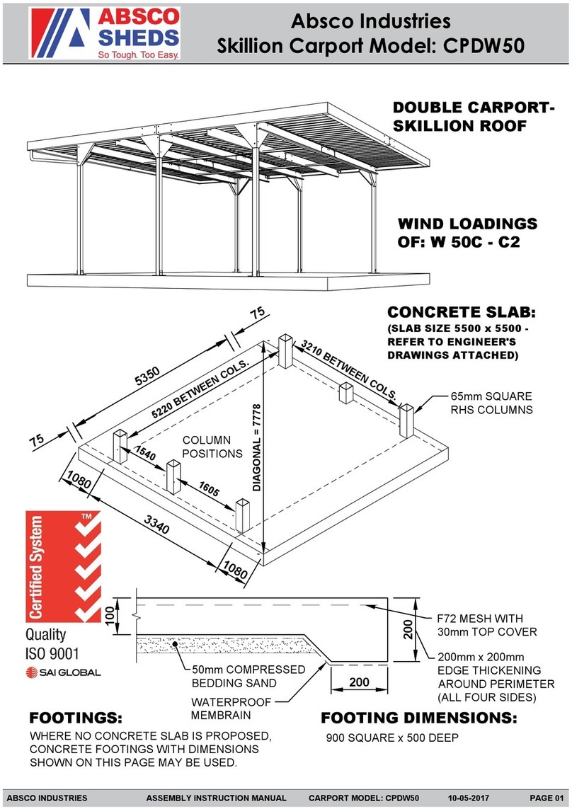
ABSCO SHEDS CPSW50 Installation guide

ABSCO SHEDS

ABSCO SHEDS CPSW50 Installation guide

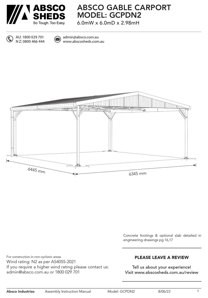
ABSCO SHEDS GCPDN2 User manual

ABSCO SHEDS

ABSCO SHEDS GCPDN2 User manual

ABSCO SHEDS CPDW50 Installation guide

ABSCO SHEDS

ABSCO SHEDS CPDW50 Installation guide

ABSCO SHEDS RG60602N2 User manual

ABSCO SHEDS

ABSCO SHEDS RG60602N2 User manual

ABSCO SHEDS RG37601N2 User manual

ABSCO SHEDS

ABSCO SHEDS RG37601N2 User manual

ABSCO SHEDS 3052UTK Installation guide

ABSCO SHEDS

ABSCO SHEDS 3052UTK Installation guide

ABSCO SHEDS CG56552N2 Installation guide

ABSCO SHEDS

ABSCO SHEDS CG56552N2 Installation guide

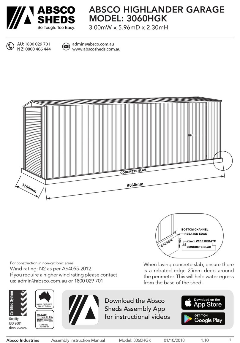
ABSCO SHEDS 3060HGK Installation guide

ABSCO SHEDS

ABSCO SHEDS 3060HGK Installation guide

ABSCO SHEDS CPSW33 User manual

ABSCO SHEDS

ABSCO SHEDS CPSW33 User manual

ABSCO SHEDS GCPSN2 User manual

ABSCO SHEDS

ABSCO SHEDS GCPSN2 User manual

Popular Tent manuals by other brands

Thermarest ArrowSpace Setup instructions

Thermarest

Thermarest ArrowSpace Setup instructions

Freespirit Adventure Series instruction manual

Freespirit

Freespirit Adventure Series instruction manual

HAMPTON BAY 5RGZ1389-WBS Use and care guide

HAMPTON BAY

HAMPTON BAY 5RGZ1389-WBS Use and care guide

Anchor 45' Aurora Tent installation instructions

Anchor

Anchor 45' Aurora Tent installation instructions

Beavertail Flip Top Blind instructions

Beavertail

Beavertail Flip Top Blind instructions

KLUTRONIC 4GROW BS 60 Assembly instructions

KLUTRONIC

KLUTRONIC 4GROW BS 60 Assembly instructions

Stabilezelte GIANT PROFESSIONAL PVC Assembly instruction

Stabilezelte

Stabilezelte GIANT PROFESSIONAL PVC Assembly instruction

Hesperide EQUADOR 165520 manual

Hesperide

Hesperide EQUADOR 165520 manual

Explore Planet Earth SPEEDY instructions

Explore Planet Earth

Explore Planet Earth SPEEDY instructions

Secret Jardin Intense 120 Assembly instructions

Secret Jardin

Secret Jardin Intense 120 Assembly instructions

Caravan Monster Reference manual

Caravan

Caravan Monster Reference manual

Glen Dimplex AAG6SE1 user manual

Glen Dimplex

Glen Dimplex AAG6SE1 user manual

Palram solid PAVO 1.5x0.9 How to assemble

Palram

Palram solid PAVO 1.5x0.9 How to assemble

Mammoth Elite 480L SA Assembly guide

Mammoth

Mammoth Elite 480L SA Assembly guide

skandika outdoor TIPII 200 Assembly instructions

skandika outdoor

skandika outdoor TIPII 200 Assembly instructions

Everbilt NS PUG 144-150D quick start guide

Everbilt

Everbilt NS PUG 144-150D quick start guide

Costway NP11460 manual

Costway

Costway NP11460 manual

Axley 014102 operating instructions

Axley

Axley 014102 operating instructions

manuals.online logo
manuals.online logoBrands
  • About & Mission
  • Contact us
  • Privacy Policy
  • Terms and Conditions

Copyright 2025 Manuals.Online. All Rights Reserved.