manuals.online logo
Brands
  1. Home
  2. •
  3. Brands
  4. •
  5. Bradford White
  6. •
  7. Boiler
  8. •
  9. Bradford White FT Series User manual

Bradford White FT Series User manual

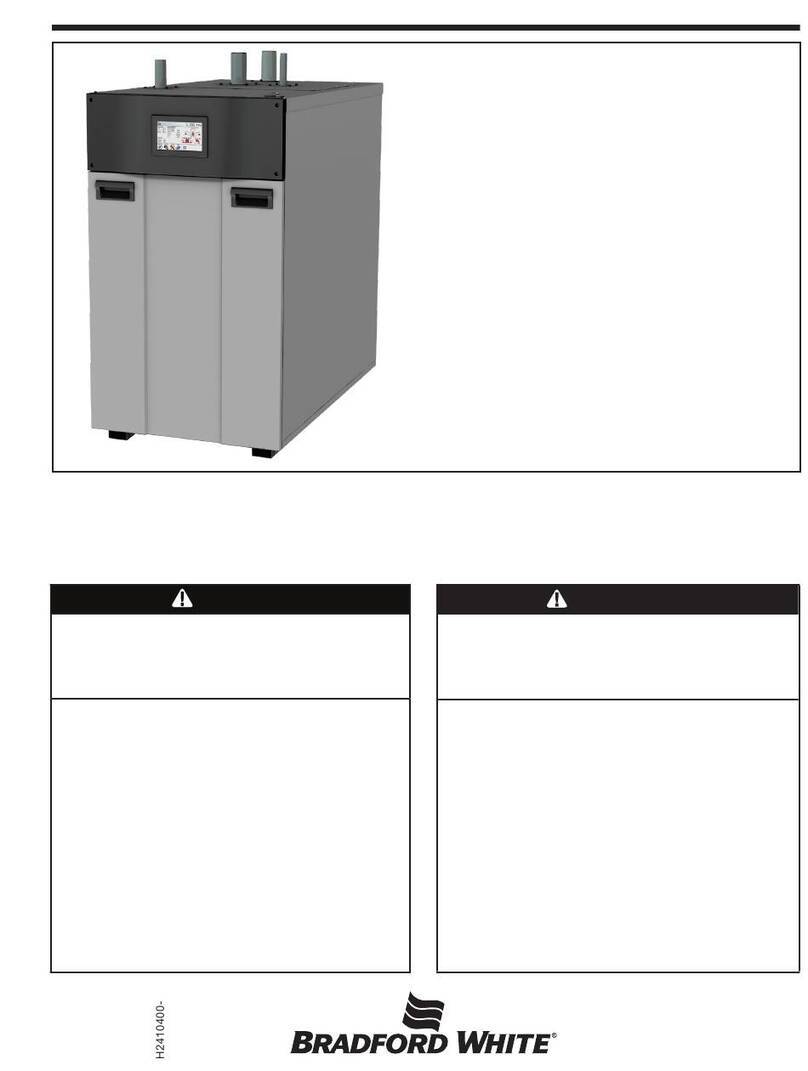
The FT Series Floor Standing, Combi and Heat Only Boiler Document 4397
1. Open 2 toggle latch clamps fixed to the upper case of
the product. Remove the front door from the product
by lifting it upwards while tilting it by about 30°.
2. Turn OFF the FT. The ON / OFF button is located
behind the front cover on the left front side of the
appliance.
3. Turn OFF the GAS and WATER supply to the FT
(valves are located on the plumbing pipes.)
4. Locate the Gas Inlet Pipe at the top left of the unit as
shown in Figure A, and loosen the Brass Fittings at
both ends of the Gas Inlet Pipe.See Figure B.
5. Completely unthread the brass fitting on the blower
end of the Gas Inlet Pipe and then carefully swing the
Gas Inlet Pipe to the left or right, just enough so that
it is out of the way. See Figure B.
6. Remove the existing natural gas nozzle or orifice.
Note that the flat side of the orifice is towards the
blower. Save the packing for re-use. See Figure C.
Model Natural Gas (NG) part
#
Propane Gas (LP) part
#
FTCF199
and FTHF199
FT1780
(8.3 mm)
FT1802
(6.35 mm)
Table A Gas Conversion Parts
The FT Series, floor standing, condensing boiler is
configured for Natural Gas (NG) from the factory. A
Propane Conversion Kit is included with every FT. The gas
conversion kit will show you how to convert your FT boiler to
propane gas. If your FT does not have the bag containing
the conversion kit, a replacement kit can be obtained.
Contact the manufacturer and request a replacement
conversion kit.
If your installation altitude is greater than 2000ft, check that
the “High Altitude”
your installation
Installer setting has been adjusted to suit
altitude. See sections 4.13 and 4.14 in the
This gas conversion kit shall be installed by a qualified
service agency in accordance with the manufacturer’s
instructions and all applicable codes and requirements of
the authority having jurisdiction. The information in these
instructions must be followed to minimize the risk of fire or
explosion or to prevent property damage, personal injury or
death. The qualified service agency is responsible for the
proper installation of this kit. The installations is not proper
and complete until the operation the converted appliance is
checked as specified in the manufacturer’s instructions
supplied with the kit. Installation must conform to local
codes and the latest edition of the National Fuel Gas Code,
ANSI Z223.1 and CAN-B149.1. Failure to follow instructions
could result in serious injury or property damage. The
qualified agency performing this work assumes
responsibility for gas conversion.
This Combi or Heat Only has already been set to burn natural
gas, but can be converted to burn LP gas. Before placing
the Combi or Heat Only boiler into operation, verify that the
proper type of gas is supplied to your combination boiler.
NOTICE
WARNING
CAUTION
Steps 1 thru 12
Orifice
FT series Boiler Installation and Operation Instructions Manual.
H2419600
Document 4388
The FT Series, Wall Combi, Gas Conversion Kit
pg 2 of 4
Figure C
Figure A
Figure B
Gas Valve
Gas Valve
ORIFICE
PACKING
ORIFICE
PACKING
FTCW140
FTCW199
Figure C
Figure B
Gas Valve
Combustion
Test Port
WARNING
This conversion shall be installed by a qualified service
agency in accordance with the manufacturer's instructions
and all applicable codes and requirements of the
authority having jurisdiction. If the information in these
instructions is not followed exactly, a fi re, an explosion
or production of carbon monoxide may result causing
property damage, personal injury or loss of life. The
qualifi ed service agency is responsible for the proper
and complete installation of this kit. The installation
is not proper and complete until the operation of
the converted appliance is checked as specified in the
manufacturer's instruction supplied with the kit. Installation
must conform to local codes and the latest edition of the
National Fuel Gas Code, ANSI Z223.1 and CAN-B149.1.
Failure to follow instructions could result in serious injury or
property damage. The qualifi ed agency performing this work
assumes responsibility for gas conversion.
AVERTISSEMENT
Ce conversion doit être installé par un organisme de service
conformément aux instructions du fabricant et tous les
codes et les exigences de l’autorité compétente. Si
les informations contenues dans ces instructions n’est
pas suivi à la lettre, un incendie, une explosion ou de
la production de monoxyde de carbone mais résultat
causant des dommages matériels, des blessures ou des
pertes de vie. Le service est responsable pour la bonne
et complète l’installation de ce kit. L’installation n’est pas
correcte et complète jusqu’à ce que le fonctionnement de
l’appareil converti est vérifi ée comme spécifi é dans le manuel
d’instruction fourni avec le kit.L'installation doit être conforme
aux codes locaux et la dernière édition du National Code de
gaz combustible, ANSI Z223.1 et peut-B149.1. Non-respect
des instructions peut entraîner des blessures graves ou des
dommages matériels. L'organisme qualifi é effectuant ce travail
suppose la responsabilité de conversion au gaz.
Figure A
Figure B
Figure C
Orice
Packing
The FT Series Floor Standing, Combi and Heat Only Boiler Document 4397
Figure D
Shown is a
Model 140
with 3" Venting
and using
Natural Gas
7. Install the new LP (propane) orifice. Re-use the
existing gasket.
8. Return the Gas Inlet Pipe to its original position
and tighten both brass fittings.
9. Per Table B, set DIP Switch 5 to OFF for LP
Propane.
10. Turn ON the GAS and WATER supply to the FT
11. Now start the unit and adjust combustion as
described in Section 4.13.
12. Upon completion of set up, write in the correct
Conversion Date and the Technicians Name to the
included gas conversion sticker. See Figure F.
Then apply that sticker adjacent to the rating
plate.
Figure E
DIP Switch State
1
199,000 BTU
ON
2 ON
3 ON
4Vent size 3" ON
Vent size 2" OFF
5NG Gas Type ON
LP Gas Type OFF
6 Max 6: ON / 7: OFF
7 Min 6: OFF / 7: ON
6, 7 Nominal 6: OFF / 7: OFF Shown is a
Model 199
with 3” Venting
and using
Natural Gas
Table B DIP Switch Settings
Gas Valve
Adjustment Port
The FT Series Floor Standing, Combi and Heat Only Boiler
Note: Please pay close attention to the orientation of the PCB board and relative switch
positions. (Actual installed PCB board is rotated 90 clockwise from shown position).
Document 4397
Document 4388
The FT Series, Wall Combi, Gas Conversion Kit
pg 4 of 4
Figure F (Conversion label)
This unit was converted on ____/____/___to _____gas
with kit #____________by______________________
(name and company __________________________
accountable)_________________________________
___________________________________________
Cette unité a été converti ____/____/____ten ______gaz
en utilisant le kit numéro _____ par______________
(nom et société_________________________________
responsable)___________________________________
_____________________________________________
H2373800D
CO2 value
Natural Gas (NG) Propane Gas (LP)
2˝ VENT 3˝ VENT 2˝ VENT 3˝ VENT
MAX FIRE 8.5 - 10.5% 9.5 - 11%
MIN FIRE 8 - 10% 9 - 10.5 %
NOTE: Installer is required to verify combustion settings as part of the installation process.
CO should not exceed 200 ppm.
Table C
Table D
Document 4388
The FT Series, Wall Combi, Gas Conversion Kit
pg 4 of 4
Figure F (Conversion label)
H2373800D
CO2 value
Natural Gas (NG) Propane Gas (LP)
2˝ VENT 3˝ VENT 2˝ VENT 3˝ VENT
FTCW (ALL Sizes) MAX FIRE 8.5 - 10.5% 9.5 - 11%
MIN FIRE 8 - 10% 9 - 10.5 %
NOTE: Installer is required to verify combustion settings as part of the installation process.
CO should not exceed 200 ppm.
Table C
Table D
NOTE: Values in the range of -.001 to -.35 Inches WC are indicative of proper set-up. If your values are outside
this range, call technical support.
Manifold Pressure Natural Gas (NG) Propane Gas (LP)
2˝ VENT 3˝ VENT 2˝ VENT 3˝ VENT
FTCF199 and
FTHF199
MAX FIRE
-0.129
”
WC -0.314
”
WC -0.169
”
WC -0.173
”
WC
MIN FIRE
-0.015
”
WC -0.015
”
WC -0.015
”
WC -0.015
”
WC
The FT Series Floor Standing, Combi and Heat Only Boiler
This boiler was converted on ____/____/____/ to____ gas
with Kit No._________ by _________ ( name and address of
organization making this conversion, who accepts the
responsibility for the correctness of this field conversion)."
« Cette chaudière a été convertie le (___/ ___/ ___) pour
fonctionner au gaz ____ à l’aide de la trousse n° par (nom et
adresse de l’organisme qui a effectué la conversion), qui
accepte l’entière responsabilité de la qualité de la conversion. »
FTCF199 and FTHF199
(and all altitudes)
Document 4397

Other manuals for FT Series

3

This manual suits for next models

2

Other Bradford White Boiler manuals

Bradford White LAARS OmniTherm OCH1250 User manual

Bradford White

Bradford White LAARS OmniTherm OCH1250 User manual

Bradford White BRUTE DELUXE BMT2H User manual

Bradford White

Bradford White BRUTE DELUXE BMT2H User manual

Bradford White Brute LX Owner's manual

Bradford White

Bradford White Brute LX Owner's manual

Bradford White JVS User manual

Bradford White

Bradford White JVS User manual

Bradford White FT Series Owner's manual

Bradford White

Bradford White FT Series Owner's manual

Bradford White Brute MagnaTech HTD User manual

Bradford White

Bradford White Brute MagnaTech HTD User manual

Bradford White Brute OmniTech BONV2500 Owner's manual

Bradford White

Bradford White Brute OmniTech BONV2500 Owner's manual

Bradford White Brute BNTH User manual

Bradford White

Bradford White Brute BNTH User manual

Bradford White Laars NEOTHERM NTH Series Owner's manual

Bradford White

Bradford White Laars NEOTHERM NTH Series Owner's manual

Bradford White Brute XTR Series Owner's manual

Bradford White

Bradford White Brute XTR Series Owner's manual

Bradford White Laars Linc MagnaTherm FT CFH1000 User manual

Bradford White

Bradford White Laars Linc MagnaTherm FT CFH1000 User manual

Bradford White Brute XTR Series User manual

Bradford White

Bradford White Brute XTR Series User manual

Bradford White Copper Brute ll BWCH User manual

Bradford White

Bradford White Copper Brute ll BWCH User manual

Bradford White Laars Pennant PNCH Series User manual

Bradford White

Bradford White Laars Pennant PNCH Series User manual

Bradford White FT Series Quick guide

Bradford White

Bradford White FT Series Quick guide

Bradford White Copper Brute II User manual

Bradford White

Bradford White Copper Brute II User manual

Bradford White Brute MagnaTech BMGH1600 User manual

Bradford White

Bradford White Brute MagnaTech BMGH1600 User manual

Bradford White Brute Deluxe BMT2H0200 Owner's manual

Bradford White

Bradford White Brute Deluxe BMT2H0200 Owner's manual

Bradford White LAARS OmniTherm ONH1250 User manual

Bradford White

Bradford White LAARS OmniTherm ONH1250 User manual

Bradford White Brute BNTH User manual

Bradford White

Bradford White Brute BNTH User manual

Bradford White FTCW199 User manual

Bradford White

Bradford White FTCW199 User manual
Bradford White Brute BNTH User manual

Bradford White

Bradford White Brute BNTH User manual

Bradford White BNTH1000 User manual

Bradford White

Bradford White BNTH1000 User manual

Bradford White Laars MASCOT FT MFTCW140 User manual

Bradford White

Bradford White Laars MASCOT FT MFTCW140 User manual

Popular Boiler manuals by other brands

Glowworm Space Saver K.F.B 60 Installation and servicing instructions

Glowworm

Glowworm Space Saver K.F.B 60 Installation and servicing instructions

Glowworm Hideaway 100C FF Instructions for use installation and servicing

Glowworm

Glowworm Hideaway 100C FF Instructions for use installation and servicing

Glowworm Betacom 24c Installation and servicing

Glowworm

Glowworm Betacom 24c Installation and servicing

AER KC Series Installation, operation & maintenance instructions

AER

AER KC Series Installation, operation & maintenance instructions

Glowworm Ultracom 24cxi Instructions for use installation and servicing

Glowworm

Glowworm Ultracom 24cxi Instructions for use installation and servicing

Heatline SARGON 30 Installation, servicing and user instructions

Heatline

Heatline SARGON 30 Installation, servicing and user instructions

Glowworm 100sxi Installation and servicing

Glowworm

Glowworm 100sxi Installation and servicing

AER Esteem 399 Installation supplement

AER

AER Esteem 399 Installation supplement

CleaverBrooks 5 manual

CleaverBrooks

CleaverBrooks 5 manual

Glowworm Ultracom2 12sxi Instructions for use

Glowworm

Glowworm Ultracom2 12sxi Instructions for use

WAHLBACH UTS10E user manual

WAHLBACH

WAHLBACH UTS10E user manual

Southbend GHD-2S owner's manual

Southbend

Southbend GHD-2S owner's manual

Galmet KW-7 Operation and installation manual, Warranty Card

Galmet

Galmet KW-7 Operation and installation manual, Warranty Card

Thermal Solutions EVCA SERIES Installation, operating and service instructions

Thermal Solutions

Thermal Solutions EVCA SERIES Installation, operating and service instructions

IDEAL MINI C24 installation guide

IDEAL

IDEAL MINI C24 installation guide

IDEAL Response SE Installation & service manual

IDEAL

IDEAL Response SE Installation & service manual

KUECHENBACH PU-100 operating instructions

KUECHENBACH

KUECHENBACH PU-100 operating instructions

Reimers JR Series instruction manual

Reimers

Reimers JR Series instruction manual

manuals.online logo
manuals.online logoBrands
  • About & Mission
  • Contact us
  • Privacy Policy
  • Terms and Conditions

Copyright 2025 Manuals.Online. All Rights Reserved.