Braemar CPL User manual

ILL1456-A
(English) (CPL CPS LCB BM)
(Original English Instructions)
CPL CPS LCB BM Evaporative Cooler
INSTALLATION MANUAL
®

WARNING: Failure to install and commission the product in compliance with these instructions, or
failure to do the job properly and competently, may void the customer's warranty. Further, it could
expose the Installer and/or the Retailer to serious liability.

ILL994-C
ILL1048-A
1. Unwrap the Cooler. Page
4
Page
4
1. Remove pads.
1. Read & understand
the safety section. Page
3
SAFETY
FIRST!
Page
5
1. Check cooler location.
2. Be aware of local regulations.
3. Discuss with customer.
Page
5
Page
4
1. Remove the venturi.
2. Remove the transition.
Page
6
Page
7
Page
11-13
Page
10
1. Locate and install the wall
control.
Page
15
Page
15
1. Set the water level.
Page
17
Page
17
ILL239-D
Page
17
Page
13
1. Install the venturi.
Page
20
Page
9
Page
14
1. Connect the components
to the electronics module.
Page
8
Step 15
Step 11 Step 12Step 10
Step 13
Step 9
Step 7Step 6 Step 8Step 5
Step 2 Step 4Step 1
Step 17 Step 19 Step 20
Step 18
1
ILL963-A ILL969-A
ILL972-A
Step 14
ILL1083-A
ILL1084-A
LESS WATER
MORE WATER
ILL998-B
Step 16
1. Clean up the site.
Step 3
1. Test run the cooler. 1. Complete the checklist.
Auto
Cool
TIMER
AUTO
COOL
ILL1128-A
Auto
Cool
TIMER
AUTO
COOL
ILL1128-A
SEELEY INTERNATIONAL – INSTALLATION MANUAL 1
1. Show the customer how to
operate their new cooler.
2. Give the customer their owners
manual.
1. Cut cable hole in dropper.
2. Position, level and secure the
dropper.
3. Flash the dropper.
1. Read and adhere to the local
electrical and plumbing rules
and regulations.
1. Run the power and wall
control cables down the
dropper.
1. Fit the float valve.
2. Fit the drain valve or bleed tray.
3. Connect water supply to the
cooler.
1. If there is a drain valve fitted to
the cooler, set the drain rate at
the wall control if necessary.
1. Fit the transition to the dropper
and secure.
2. Break weatherdamper transport
clips and fit weatherdamper.
1. Transport the cooler to the roof.
2. Always handle the cooler using
2 people.

EXPLODED VIEW
2
®
CPL CPS LCB BM Evaporative Cooler
®
When ordering spare parts, please specify the model/serial number and colour of your cooler.
1
2
3
4
5
6
7
8
9
9
23
11
12
13
14
15
26
24
25
27
28
16
18
19
20
21
22
17
10
ILL 1151-D
ILL972-C
ILL985-D
ILL973-B
1. Dropper Grommet
2. Transition
3. Weatherseal
4. Transition Plug
5. Pad Frame
6. Flexible Hose
7. Solenoid Cover
8. Solenoid Valve
9. Extension Tube
10. Tank
11. Corner Pillar
12. Water Sensor
13. Float Valve
14. Water Pump
15. Drain Valve
16. Motor Power Lead
17. Power Cord Assy
18. Electronics Module
19. Pump Hose
20. Venturi / Fan Assy
21. Lid
22. Distributor Cap
23. 3/4” to 1/2” BSP Adaptor
24. Bleed Funnel
25. Bush, Bleed Funnel
26. Nut 40mm (Bleed Funnel & Drain Valve)
27. Drain Adaptor
28. Nut, Drain Adaptor
Water Inlet Configuration
CPL, CPS, LCB, BM - Bleed Funnel
Water Inlet Configuration
CPL, CPS, LCB, BM - Drain Valve
Water Outlet Configuration
CPL, CPS, LCB, BM - Drain Valve
Water Outlet Configuration
CPL, CPS, LCB, BM - Bleed Funnel
CPL, BM Motor/Fan/Venturi Assy
CPS, LCB Motor/Fan/Venturi Assy

SAFETY
EMPLOYER AND EMPLOYEE RESPONSIBILITIES
Installer and Maintenance Contractors
Risk Assessment
Some points to consider:
The installation and maintenance of evaporative air conditioning units at height has the potential to create Occupational Health and Safety
issues for those involved. Installers are advised to ensure they are familiar with the relevant State and Federal legislation, such as Acts,
Regulations, approved Codes of Practice and Australian Standards, which offer practical guidance on these health and safety issues.
Compliance with these regulations will require appropriate work practices, equipment, training and qualifications of workers.
Seeley International provides the following information as a guide to contractors and employees to assist in minimising risk whilst working
at height.
A risk assessment is an essential element that should be conducted before the commencement of work, to identify and eliminate the risk
of falls or to minimise these risks by implementing control measures.
A risk assessment of all hazardous tasks is required under legislation.
There is no need for this to be a complicated process, it just is a matter of looking at the job to be done and considering what action(s) are
necessary so the person doing the job does not injure themselves.
This should be considered in terms of:
What are the chances of an incident happening?
What could the possible consequence be?
What can you do to reduce, or better still, completely get rid of the risk?
What is the best and safest access to the roof and working areas?
If a worker is alone, who knows they are there and if they get into difficulty, how can they summon help? (Call someone on the
ground? Mobile phone? etc.)
What condition is the roof in? Should the trusses, underside or surface be checked?
Does the worker have appropriate foot wear? (Flat sole jogger type is advisable)
Are all power cables / extension leads safe and appropriately rated?
Are all ladders, tools and equipment suitable in good condition?
Where ladders are to be used, is there a firm, stable base for them to stand on? Can they be tied or secured in some way at the top?
Is the top of the ladder clear of electricity supply cables?
Is there a roof anchor to attach a harness and lanyard to? If so, instruction should be issued for the use of an approved harness or
only suitably trained people used.
Are all tools and materials being used, prevented from slipping and falling onto a person at ground level? Is the area below the work
area suitably protected to prevent persons walking in this area?
Does the work schedule take into account weather conditions, allowing for work to be suspended in high winds, thunder
storms/lightning or other types of weather giving wet, slippery surfaces?
Is there an on-going safety check system of harnesses, ropes, ladders and access/lifting equipment and where they exist on roofs,
anchor points before the commencement of work?
Is there a system which prevents employees from working on roofs if they are unwell or under the influence of drugs or alcohol?
Are there any special conditions to consider i.e. excessive roof pitch, limited ground area, fragile roof, electrical power lines?
!
!
!
!
!
!
!
!
!
!
!
!
!
!
!
!
OTHER IMPORTANT REQUIREMENTS
!
!
!
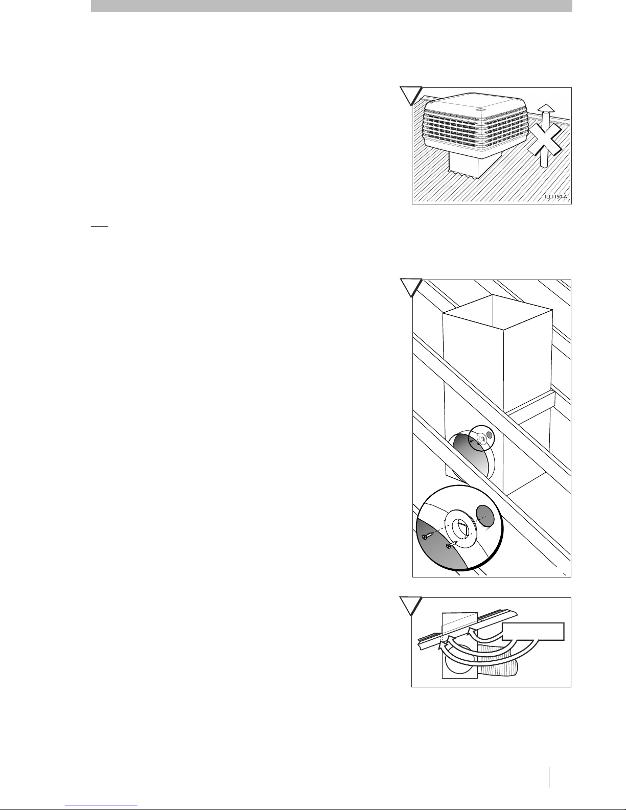
Never force parts to fit because all parts are designed to fit together easily without undue force.
Never drill any holes in the primary base surface or side walls of the bottom tank (reservoir) of the cooler.
Check the proposed cooler location, to ensure that it is structurally capable of supporting the weight of the cooler, or provide an
adequate alternate load bearing structure.
SEELEY INTERNATIONAL – INSTALLATION MANUAL 3

REMOVING THE VENTURI
Once the pad frames have been removed,
detach the venturi and fan assembly.
For LCB & CPS models,
Lift the venturi and fan assembly out of the
cooler. Take care with the motor lead, which
will be sitting loosely in the bottom of the
cooler.
The venturi and fan assembly can be placed
on to the ground until the rest of the cooler has
been installed on the dropper.
!
!
disengage the
two venturi clips as shown (Fig 3A).
For CPL & BM models, undo the two
screws that retain the venturi during
transport (Fig 3B) and dispose of the
screws thoughtfully, as they are no longer
required.
2
1
3
12
UNWRAP THE COOLER
Cut and remove the shrink wrap from the cooler and dispose of the wrap
thoughtfully.
REMOVING THE PAD FRAMES
To remove a pad frame, first
disengage the top clips of the pad
frame. Insert a screw driver tip into
the slot between the lid and the top
of the pad frame and lever until
disengagement occurs (Fig 2 part 1).
Take hold of the pad frame and pull it
towards you until the internal side
clips disengage (Fig 2 part 2).
Pivot the pad frame outwards and lift
up. Take care not to damage the pad
(Fig 2 part 3).
Repeat the steps above with the
three remaining pad frames.
REMOVING THE TRANSITION
Turn the cooler onto its side to remove the transition. There are clips in each of
the four corners that will disengage once the transition is given a firm pull
(Fig 4).
If any of the corners are difficult to remove do not use excessive force. Gently
squeeze the clips together and remove the transition one corner at a time.
4
4
®
CPL CPS LCB BM Evaporative Cooler
®
A = LCB, CPS B = CPL, BM
3
ILL1152-A ILL1153-A
ILL1154-A
ILL1002-B

ILL963-A
ILL182-G
DROPPER SECURELY
ATTACHED TO RAFTER
ON THREE SIDES
6
7
5
COOLER LOCATION
Ensure the location is a minimum of: 3m from a solid fuel heater flue, 1.5m
from a gas flue, 5m from a sewer vent.
Check the proposed cooler location, to ensure that it is structurally capable of
supporting the weight of the cooler, or provide an adequate alternate load bearing
structure.
Always locate the cooler where it will receive a plentiful supply of fresh air. Not in a
recess where it may be starved for air or where the air is polluted.
Allow adequate access around the cooler for maintenance. Provision must be
made for access to electricity, water supplies and drains.
The ideal location for the cooler is in a central position on the roof (away from
sleeping areas and where people spend most of their time) so that the duct runs are
of approximately the same length.
Carefully consider neighbouring residences and noise levels when locating the
cooler, if necessary talk to the customer and the neighbours before carrying out the
installation.
Note! Do you need to discuss the installation of items like safety anchor
points or access with the customer?
The 550mm x 550mm dropper duct must have a raw edge or safe edge at the top.
Do not turn in a flange as this will interfere with the transition and weatherdamper.
Remove the transition and flash the dropper carefully, so there is no chance of any water
entering the roof space.
MOUNTING THE DROPPER
Cut the 50mm diameter cable exit hole in the dropper then fit and screw the cable
grommet into position (Fig 6). Locate the hole so that the cables will not interfere with the
fully opened weatherdamper.
Fit the transition temporarily to the dropper (Fig 9 page 6), then locate the dropper into
position. Use a spirit level to ensure the top of the transition is level.
Important!
The dropper must be securely fixed to the roof structure on at least 3 sides (Fig 7).
This may require the addition of some extra structural timber.
The dropper must never sit directly onto any ceiling joists or beams, as there may
be associated noise transfer, causing problems after installation, including
possible ceiling damage.
5
SEELEY INTERNATIONAL – INSTALLATION MANUAL

ILL983-A
ILL988-A
11
ILL1049-A
8
INSTALLING THE TRANSITION AND WEATHERDAMPER
Refit the transition onto the dropper as shown. Ensure that it
is oriented correctly, as shown by the engraved detail on the
transition (Fig 8).
Check the level of the transition on the dropper with a spirit
level, placed across the flats in both directions.
Once level, begin securing the
transition to the dropper using the
screws provided. There are eight (8)
‘V’ notch locations for screws.
Only use the screws provided.
These must be used in the correct
positions (Fig 10) to prevent
interference with the
weatherdamper. All eight (8) screws
must be used. Check the level
periodically before driving in all the
screws.
IMPORTANT: There must be no
obstructions to the weatherdamper opening
fully as it will adversely affect the
performance of the cooler.
Break off both clips on the transition that retain
the weatherdamper (Fig 11) .
Ensure that the weatherdamper flaps open all
the way and do not interfere with the dropper
or any screws. The flaps should move freely
through 90º.
10
6
®
CPL CPS LCB BM Evaporative Cooler
®
9
BREAK
OFF
CLIP

13
TRANSPORTING THE COOLER TO THE ROOF
Do not take risks when raising the cooler to the roof
for installation. Use safety equipment, appropriate
procedures and always have assistance.
It is recommended that at least two (2) people move
the cooler into position and that the transition, pad
frames, venturi assembly and any unsecured objects
are removed beforehand.
Attach ropes or slings through the central tank hole
(Fig 12). Always handle the cooler with care.
If you intend to pull the cooler onto the roof using a
ladder as a slide, then guide the cooler on the
underside of the tank (Fig 13).
Once the cooler is on the roof, carefully lift the
assembly onto the transition and into place. The
assembly will only fit onto the transition in one
orientation.
Ensure that the clips in all four corners engage
correctly. Do not use any screws to
fix the cooler to the transition (Fig 14).
IMPORTANT: Do not place the venturi assembly
into the cooler at this stage.
12
14
7
SEELEY INTERNATIONAL – INSTALLATION MANUAL
LCB, CPS CPL, BM

16
ILL1288-A
Plug
CABLE INSTALLATION
NOTE! Leave the electronics module safely in the tank, as the motor
plug will require connection to the underside of the module when the
venturi is refitted into the Cooler.
WARNING: Do not let cables, cable ends, or the control box get wet.
After fitting the cooler to the dropper, disconnect the electronics module from
the tank by removing the screw under the switch as shown (Fig 15). The
isolation switch cannot be activated with this screw removed. Place the
electronics module and the screw to one side in the tank.
Your installation kit includes the power cord and thermostat cable. Drop the
power cord plug end along with the taped end of the thermostat cable into
the dropper duct. Route the power cord socket end with the thermostat
cable upwards through the corner hole in the transition and out the tank
cavity as shown. Lock the power cord socket in place by sliding the plug in
sideways as shown.
The plug will only insert one way, with the chamfered end first (Fig 16). For
now, leave the thermostat cable end in the tank as it will be connected later.
Position the cords in the dropper so they will be accessible from inside the
roof space.
Pass the cords through the grommet in the dropper.
Do not coil the excess length of the power cord. Place excess length of the
thermostat cable in the roof cavity and not inside the cooler or dropper.
Push the cables into the cable slot in the transition as shown (thermostat
cable first) and then seal the hole with the plug provided.
IMPORTANT
Test the weatherdamper operation and ensure that the cables in the
dropper do not interfere with the operation of the weatherdamper.
8
®
CPL CPS LCB BM Evaporative Cooler
®
CPMD equipped EVAPORATIVE
COOLER
BRAEMAR SCC
SPECTROLINK
HEATER CONTROLLER
BRAEMAR GAS HEATER
The SCC must be set to “COOL 1"
to operate an evaporative cooler
CPMD
BSC
SCC
CPMD COMM’S LOOM SCC COMM’S LOOM
Heater
power
supply
To “CC”terminal labelled
“Spectrolink Multi Zone”on BSC
Cooler
power
supply
To “CPMD”terminal labelled
“To EVAP Control”on BSC
ILL1478-A
CONNECTING THE COOLER TO A BRAEMAR SPECTROLINK GAS
HEATER CONTROLLER
This cooler can be inter-connected to a Braemar Gas Heater and operated
from the Braemar SCC Spectrolink Heater controller. Any Seeley
International evaporative cooler equipped with a CPMD Electronic Module
can be operated this way. The following diagram (Fig 17) shows the
connections required:
17
15

ELECTRICAL REQUIREMENTS
.
Specification : 240V / 50Hz Single Phase
Installation of the cooler must conform to National, State and Local electrical rules, regulations and standards.
It is a requirement of Seeley International that all coolers be wired with a dedicated circuit to the distribution board adhering to
local and national wiring standards
A 10A socket outlet within one metre of the dropper’s cable exit hole is also required.
The electronics module is fitted with a 12A resettable circuit breaker. To reset the circuit breaker turn off the isolation switch, remove the
electronics module and push the manual reset toggle switch located underneath the electronics module.
WATER REQUIREMENTS
Installation of the Cooler water supply must conform to local plumbing rules, regulations and standards: AS/NZS 3500.1
The following specifications for water supply are required:
A permanent water supply is required to be connected to the float valve. The water connection point is located on the underside of the
cooler.
Install a manual ball valve type water shut-off in the water supply line adjacent to the cooler, this allows the water supply to be isolated
whenever work needs to be done on the cooler, subject to local plumbing regulations. It is not recommended to use a non-return type shut
off valve.
: The water connection is a 1/2”BSP compression fitting on the end of a flexible hose. This can fit
directly onto the water pipe or be screwed directly onto the manual water shut-off valve.
Always ensure that the water pipe connection does not place sideways strain onto the float valve.
: The water connection fitting is a 1/2”BSP male adaptor suitable for a compression fitting. Do not
fit the manual water shut-off valve directly onto the plastic nipple.
Water Connections : ½”BSP
Water Supply : 800 kPa (115 psi) MAXIMUM
Water Supply Temperature : 40°C MAXIMUM
!
IMPORTANT! Flush the water pipe to remove any swarf before final fitting.
Important If the water pressure exceeds this maximum specification then a pressure reducing valve is required and must be
supplied and fitted by the installer.
In areas subject to freezing or where freezing may occur, drain down or frost protection must be fitted.
For coolers having the drain valve fitted
For coolers having the bleed tray fitted
9
SEELEY INTERNATIONAL –INSTALLATION MANUAL

ILL1066-B
1.
2.
3.
Use the bracket as a template.
1. Drill the 16mm hole for the wall control
cable.
2. Drill the 5mm holes for the wall plugs.
3. Insert the wall plugs into the holes. Align
and screw the bracket into position using
the supplied screws.
Fixing the wall control bracket to a
plasterboard wall
1
2
3
ILL 1210-A
Fixing the wall control bracket to a
brick wall
To mount the wall control bracket on a brick
wall, follow the previous instructions (Fig 18
using the wall plugs and screws provided.
Note that the wall plugs require 6mm holes.
Mount the controller following the procedure
in Fig 19.
1. Pull the wall control cable through the
larger hole and plug it into the wall control.
2. Feed the excess cable back into the hole
and seal. Slide the wall control over the
protruding bracket tabs.
3. Pull the wall control down so the bracket
tabs engage and locate with the keyway
slots on the rear.
Fitting the wall control to the mounting
bracket
ILL1068-B
18 20
19
LOCATING THE WALL CONTROL
The wall control should be placed approximately 1.5 metres above the floor, in the most used room in the home. This will give the
optimum temperature sensing and operating position for the user.
:
•Avoid direct sunlight exposure.
•Avoid mounting on external walls.
•Avoid mounting the wall control near heat sources such as stoves and televisions.
•Do not locate in the direct airflow of the duct outlets.
•Do not locate in strong drafts or in dead spots such as cupboards/drawers.
•Always fill in the cable entry hole. Air coming through the wall may interfere with the temperature measurement.
Placement is critical for correct functioning of the thermostat (incorporated in the wall control). The following points must be taken
into consideration
CAUTION! Always make sure there are no electrical cables, gas or water pipes, or the like, behind where you intend to drill.
Running the wall control cable to the wall control
! Take care not to damage the cable or plug during this process.
Using the loop on the end, draw the cable through the wall cavity to the hole made at the wall bracket. Carefully remove the tape
from the cable loops and check that the plug has not been damaged. Connect the cable to the wall control and mount the wall
control onto it’s bracket.
Always seal the cable entry hole.Important
10
®
CPL CPS LCB BM Evaporative Cooler
®

BLEED TRAY
(Standard for CPL, CPS & BM models, optional for LCB models)
! If the water sensor is fitted, you will need to disconnect it from the
Electronics Module and remove it from the Cooler completely. Then fit the
shorting plug (supplied in the Bleed kit) to the socket where the water
sensor was fitted (Fig 32).
The bleed funnel reduces the accumulation of salts and minerals in the cooler. It
also acts as an overflow and a drain.
Assemble the bleed funnel as shown (Fig 22).
Make sure the bleed funnel is correctly oriented and that the o-rings are fitted
before placing it into the hole. Screw the nut up tightly by hand underneath the
cooler.
Make sure that you use the correct drain adaptor. Drain-water from the bleed
funnel must be carried away to a suitable discharge point on the building or
property in accordance with local regulations. Do not drain directly onto the roof
surface.
The bleed rate required will vary according to water quality, but should initially be
set to the minimum rate as set out in the table.
LCB 250 BM500 CPL450 CPS450 1 Plug in
LCB 350 BM750 CPL700 CPS700 1 Plug in
LCB 450 BM900 CPL850 CPS850 2 Plugs in
LCB 550 BM1150 CPL1100 CPS1100 2 Plugs in
Push the remaining plugs into the blind holes provided. In poor quality water
areas where the salt and mineral contents are high, adjust the bleed rate by
inserting one or more extra plugs than specified in the table.
Note
WATER CONNECTION
FLOAT VALVE
If you do not intend to install the drain valve, assemble the float valve to the
cooler as shown (Fig 21). Ensure all washers and o-rings are in place. No thread
tape is required. Do not over tighten.
Make sure the float is centrally positioned and up and down movement is
unrestricted.
See page 15 for setting the correct water level.
Connect the water supply to the float valve nipple.
21
22
11
SEELEY INTERNATIONAL –INSTALLATION MANUAL

SOLENOID VALVE
(Standard for LCB models, optional for CPL, CPS & BM models)
If the drain valve is to be installed instead of the bleed funnel, assemble the float
valve to the cooler with the solenoid valve as shown (Fig 23). Ensure all washers
and o-rings are in place. No thread tape is required. Do not overtighten.
The solenoid valve has been screwed into the flexible hose, and must not be
disconnected. (Note:
Tighten the solenoid valve until it seals against the rubber washer and is in the
orientation shown such that the solenoid cover will clip on over the top (Fig 24).
The water solenoid is required to be installed in the
direction of flow as per the arrow indicator on the solenoid, Fig 23).
Connect the supplied cable to the solenoid valve, then push the other end
through the hole in the transition as shown. Pull the cable through from inside the
cooler and route the cable as shown (Figs 24 & 25). This will be connected later.
Now clip the solenoid cover in place and connect the flexible hose to the mains
water supply.
DRAIN VALVE
(Standard for LCB models, optional for CPL, CPS & BM models)
Assemble the drain valve instead of the bleed tray if you have installed the
solenoid valve.
Assemble the drain valve as shown (Fig 26).
Make sure that the o-ring is fitted before placing the drain valve into the hole.
Screw the nut up tightly by hand underneath the cooler.
Make sure that you use the correct drain adaptor.
Make sure the drain water discharge flows freely away from the cooler.
Drain water must be carried away to a suitable discharge point on the
building or property in accordance with local regulations.
Do not drain directly onto the roof surface.
!
!
!
!
!
!
23
26
24
12
®
CPL CPS LCB BM Evaporative Cooler
®
25
Note! The Solenoid Valve has a water flow directional arrow.
IMPORTANT: For coolers fitted with a drain and solenoid valve, it is a
requirement to fit the new detachable hose set supplied.
Any old hose sets should not be re-used.

INSTALLING THE VENTURI/FAN ASSEMBLY
The venturi/fan/motor assembly can now be carried
up onto the roof. (Place the assembly into the cooler
and let it rest near its cavity in the tank.) The
assembly will only fit into the tank in one orientation
(Fig 28).
For LCB/CPS models only: Important
Important
! Before
fitting the venturi into position, make sure the
motor lead exits through the venturi notch and
located in the motor lead channel (Fig 28).
Ensure the bottom of the lead is aligned with the
bracket inside the tank (Fig 29-B). Failure to do
this may result in the cable being caught between
the outside of the bracket and the venturi.
! Make sure the venturi is correctly and
symmetrically located all the way around it’s
cavity. Check this by making sure the venturi sits
inside the locating ridge all the way around. (Fig
29-C). Ensure the plug/lead assy is not caught
under the bottom lip of the venturi, by pulling the
lead through fully.
For CPL and BM models only: D
Feed the motor lead through the channel (Fig 29 - A)
in the mounting bracket where the Electronics
Module sits. Snare the lead into one of the brackets
at the top of the opening (Fig 29-A).
o not refit the 2
transport screws removed whilst initially dis-
assembling the venturi. Dispose of these screws
thoughtfully. For detail, refer to page 4 describing the
venturi removal steps.
27
28
B
A
C
ILL1229-D
WATER SENSOR
(Standard for LCB models, optional for CPL, CPS & BM models)
If you installed the drain valve, assemble the water sensor as shown by clipping the
sensor to the tank (Fig 27). Ensure that the clip fully engages.
Route the sensor cable through the cable supports in the tank as shown and leave
the end clear of any water. The cable will be plugged in later.
13
SEELEY INTERNATIONAL –INSTALLATION MANUAL
29
ILL994-C
LCB, CPS CPL, BM

33
ILL496-A
30
32
ELECTRICAL CONNECTION
Connect the motor cable to the base of the Electronics Module. It is a
polarised plug and will only insert one way. Ensure it is secured fully so that
its retention clips are engaged.
Route the end of the wall control cable out of the cavity via the same
channel as the motor cable (Fig 30). Ensure you have about 200mm (8”) of
wall control cable outside the cavity.
With both cables in place (inside the channel, Fig 30), re-assemble the
electronics module and screw it to the tank as shown (Fig 31).
IMPORTANT: The isolation switch cannot be activated unless this
screw is fixed in place, as shown in Fig 31.
Plug the wall control cable to the electronics module according to Fig 32.
If you have installed the drain valve, remove the shorting plug (pre-installed
for CPL, CPS and BM models), which will be connected to the water sensor
socket on the control box (Fig. 32)
Then connect the water sensor and solenoid valve plugs as shown. Ensure
the plugs are connected in the correct orientation (see bottom of Fig 32).
Route the drain valve cable as shown before connecting it to the electronics
module (Fig 33).
Finally, turn on the isolation switch, replace the pad frames (except the front
pad frame to allow access) and turn on the power at the GPO and the
distribution board.
If you have installed the bleed tray, ensure the shorting plug is fitted to the
water sensor socket on the control box (Fig 32).
The shorting plug is pre-installed for models CPL, CPS and BM, and is
included in the optional Bleed Funnel kit for LCB models.
IMPORTANT!: If a drain valve is connected, do not connect the pump
plug yet. Otherwise fit the pump plug to the electronics module, as
shown in Fig 32.
IMPORTANT!: Ensure the cables cannot rest in the water once the tank
is filled, and are connected in the correct orientation as shown at the
bottom of Fig 32.
31
14
®
CPL CPS LCB BM Evaporative Cooler
®
ILL1062-F
Connector Orientation
7
Shorting
Plug
MINIMUM SPEED ADJUST
PUMP
DRAIN
INLET SOLENOID
WALL CONTROL
OR RECEIVER
DIAGNOSTIC
LED’S
WATER SENSOR
(OR SHORTING
PLUG FOR BLEED
FUNNEL)

If the level is too high rotate the float
clockwise. If it is too low rotate the float
anti-clockwise, as shown (Fig 36).
If you installed the drain valve, a
complete drain can be initiated by
holding down both S and T
for 1 second when the thermostat is
OFF. The signal “ ” will display to
confirm the drain operation has
activated.
dr
36
35
34
15
SETTING THE CORRECT WATER LEVEL
If there is no drain valve fitted, just turn on the water supply to fill the tank. If the drain
valve is fitted, you need to leave the pump disconnected whilst setting the water level.
If you have installed the drain valve instead of the bleed funnel you will need to turn
the water on by pressing COOL on the thermostat while it is in the OFF state. The
water inlet valve will now remain open for 15 minutes.
When the tank is full the float valve will stop the water entering the cooler. Wait for this
to happen and observe the level. The correct water level is approximately 5mm below
the surface of the tank the float valve is mounted on (Fig 35).
SEELEY INTERNATIONAL –INSTALLATION MANUAL
DRAIN RATE ADJUSTMENT
For CPL, CPS and BM models (optional Drain Valve operation)
NOTE: The following process must be carried out within four (4) minutes of
mains power being applied to the Cooler. If unsure of the time since the
mains power was applied, remove mains power to the cooler for a minimum
of six (6) seconds and then re-apply power so the mode can be entered.
For LCB models, the drain frequency is managed by salinity control. There is no
need for adjustment.
If you installed the drain valve instead of the bleed funnel then the water will drain
every two (2) hours during cooling operation. This default time can be adjusted
according to water quality. The water change regularity can be increased in areas
where water salinity is high or quality is relatively low. Maintaining the water
quality helps the cooler operate more effectively.
While the thermostat is OFF, hold down AUTO for at least 3 seconds and then
press while still pressing AUTO.
The setting “A1”will be displayed, release both buttons. Now press until
“A8”is displayed and then press AUTO.
A number will now be displayed. Press or until the number
displayed corresponds to the desired drain delay time according to the table
below.
Press AUTO to complete the adjustment.
Exit the programming mode by pressing ON/OFF. Abort an alteration by pressing
ON/OFF instead of AUTO.
ILL1080-A
ILL1083-A
ILL1084-A
Display Number Time between drains
05 1.3 hours
07 STANDARD 2 hours
11 4 hours
15 10 hours

40
WATER PUMP CONNECTION
(Drain valve option only)
! Ensure the splash protection flap shown (Fig 38) is in
place.
! Do not run the pump while the pad frames are off and the
fan is on.
Switch off the electronics module. Route the pump cord as shown (Fig 37)
and connect the pump to the electronics module. Switch the electronics
module on.
IMPORTANT
WARNING
39
LED should be
green
37
38
16
TEST OPERATION
Note!
Check that the green light on the electronics module is on and double
flashing every 2 seconds (Fig 39). This indicates that power is connected to
the electronics module. Make sure that the flexible cover on the electronics
module is fully closed as shown (Fig 38).
Replace the remaining pad frames and run the cooler. To start the
cooler, press ON/OFF on the thermostat. If the cooler has not been on
before it will start in Manual control mode (“Man”will display as shown). The
display will flash “Pre-Cool Cycle”and the pump will operate to saturate the
pads. The pump will start immediately for units with the bleed tray, for units
with a drain valve there will be a delay before the pump commences
operation (30 seconds after the water reaches the water sensor).
The “Pre-Cool”will be in operation for 2 minutes after the pump starts, then
the fan will start automatically.
Stop the cooler and check that each of the pads are evenly saturated.
If on initial start up the word “Service”appears on the controller and
by pushing the button nothing changes on the display, then you will
need to establish communication between the wall control and the electronic
controller. Simply push and hold the button for approx. 10
seconds or until the word “Service”disappears. If by pushing the
button a number appears refer to Page 19 for fault codes.
ON/OFF
ON/OFF
(Fig 40)
®
CPL CPS LCB BM Evaporative Cooler
®
ILL1014-G

Please take a few moments to explain to the customer the following:
How far the windows need to be opened.
How to turn the unit on.
Explain the “PRE COOL”mode.
How to operate the cooler “manually”.
How to operate the cooler in “vent”mode only.
How to operate the cooler in “auto”mode.
How to drain the cooler (if drain valve fitted).
How to turn the power and water off.
Maintenance requirements.
Present the customer with their warranty card for their attention.
Present the customer with their owners manual, and encourage them to keep it for future
reference.
!
!
!
!
!
!
!
!
!
36
41
42
TIMER
AUTO
COOL
ILL1128-A
ILL1211-A
43
TESTING THE COOLER
Once you are satisfied that the Cooler is installed and commissioned correctly, it is
important to run the cooler and ensure that everything is working as it should.
Check that the unit runs quietly and with an even distribution of air to all outlets.
If a drain valve is fitted, initiate a drain of the tank by pressing both the up and down
buttons together, with the wall control in the “OFF”state (Fig 41). Check the drain fittings
and pipes, making sure there are no leaks. Ensure the drain water discharges freely
away from the cooler.
CLEAN UP THE SITE
Clean up and tidy the premises, removing all rubbish. Your aim should be to have the
customer not even aware that you have been, apart from having their new cooler
installed to enjoy!
SHOW THE CUSTOMER THEIR NEW COOLER
This is a good time to explain the features and principles of Evaporative Ducted Cooling to
the new owner. Explain the wall control operation, how to exhaust the premises, and how to
best run their cooler.
17
SEELEY INTERNATIONAL –INSTALLATION MANUAL

PROBLEM: Inadequate cooling
CAUSE REMEDY
1. Pump not working correctly Check plug, wiring and circuit breaker. Check water level
and sensor. Impellor may be jammed or obstructed. Rectify
fault or replace pump.
2. Dry pads. Check water flow to pads. Inspect fitment of distributor cap.
Check for blocked or kinked hose. If blocked, dismantle,
clean and flush or unkink the hose. Check the inlet solenoid
filter for blockage.
3. Leaking ducts Find leaks and seal.
4. Weatherdamper failing to open. Break off transport clips. Check for weatherseal/transition
screw interference. Check minimum fan speed setting.
PROBLEM: Motor starts and stops at intervals
CAUSE REMEDY
1. Loose electrical connections. Check all electrical connections.
2. Fan not turning freely. Determine cause and rectify.
3. Weatherdamper failing to open. Break off transport clips. Check for weatherseal/transition
screw interference. Check minimum fan speed setting.
PROBLEM: Continually leaking water when turned off
CAUSE REMEDY
1. Dirt under drain valve seal. Clean and refit seal, clean any remaining debris from tank.
2. Dirt under float valve seal. Clean and refit seal.
3. Damaged float valve seal. Replace Float Valve seal.
4. Water level set too high. Set water level as described.
5. Water pressure too high. Install pressure reducing valve.
PROBLEM: Unpleasant odour
CAUSE REMEDY
1. Odour from new pads Allow time to condition by running the cooler.
then allow the tank to re-fill.
Drain the water,
PROBLEM: No variable speed
CAUSE REMEDY
1. Faulty electronics module or wall control. Replace electronics module or wall control.
2. Minimum fan speed set too high. Adjust minimum fan speed (Fig 32 page 14).
18
®
CPL CPS LCB BM Evaporative Cooler
®
This manual suits for next models
3
Table of contents
Other Braemar Air Conditioner manuals