OPERATION cont.
6
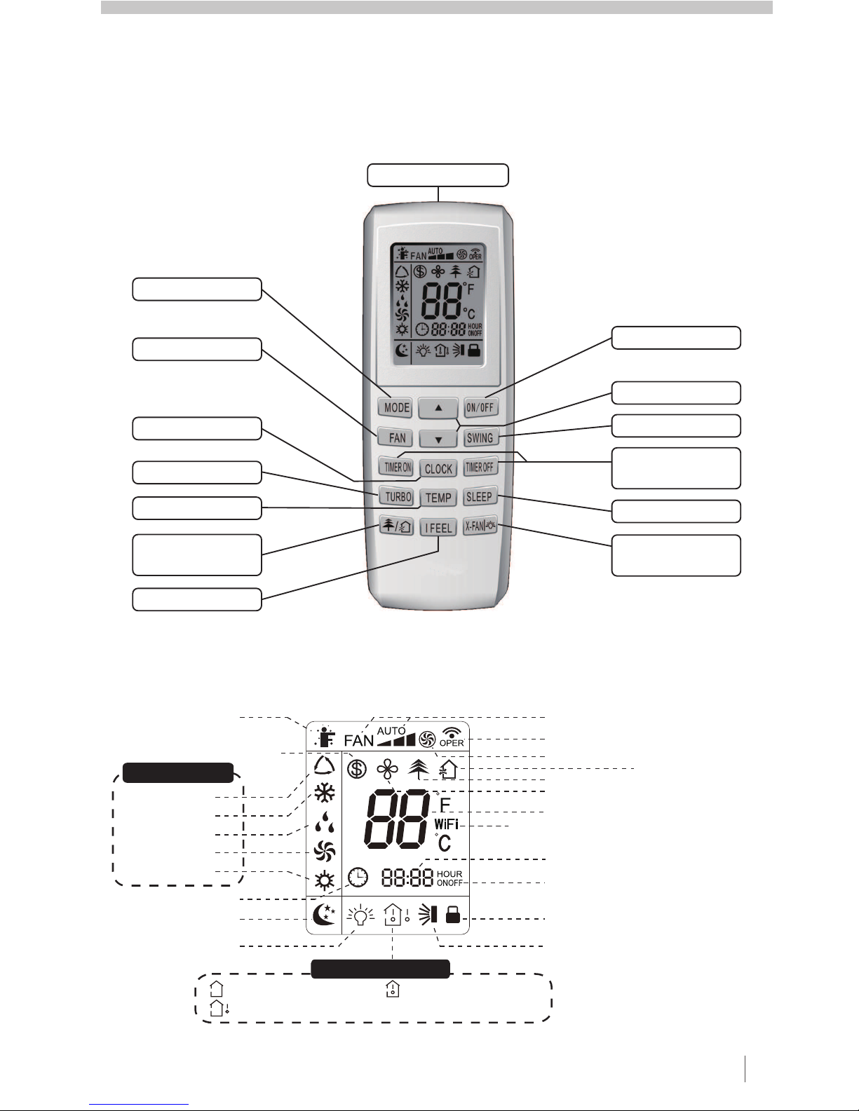
ON / OFF
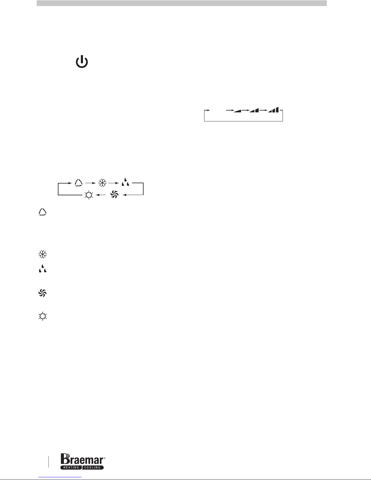
MODE
Press to turn the power on or off.
SLEEP function will be cancelled when
power is turned off.
Press to toggle between AUTO,
COOL, DRY, FAN and HEAT modes.
The remote controller & indoor will
display the below icons:-
AUTO Mode - cycles between
COOL and HEAT modes
depending on ambient
temperature.
COOL Mode - refrigerated cooling
DRY mode - for extracting
moisture from the air.
FAN mode - Fan only operation
(no cooling).
HEAT mode - reverse cycle
heating.
AUTO mode is the default setting.
During AUTO mode, the SET
temperature will not be Note: to
prevent cold air after starting HEAT
mode, unit will blow air after a 1-5
minute delay.
FAN SPEED
CLOCK
Press the FAN button to toggle
between AUTO, Low, Medium and
High speed.
AUTO fan speed is default on power
up. In DRY mode, only Low FAN
speed is selected.
Use to adjust the SET temperature
within the range 16-30°C (61-86°F).
Hold the button down for quick
adjustment.
Note: Temperature adjustment is
unavailable in AUTO mode.
Press the CLOCK button to set the
clock time. will flash on the display,
and the clock can be adjusted by
pressing the
▲ ▼
▲ ▼
/
or buttons within 5
seconds, using a 24 hr clock. Once
the correct time is set, press the
CLOCK button again to confirm the
clock setting. will be displayed
continuously, this indicates the clock
time is set. Set the correct time to
enable the TIMER function to work
correctly.
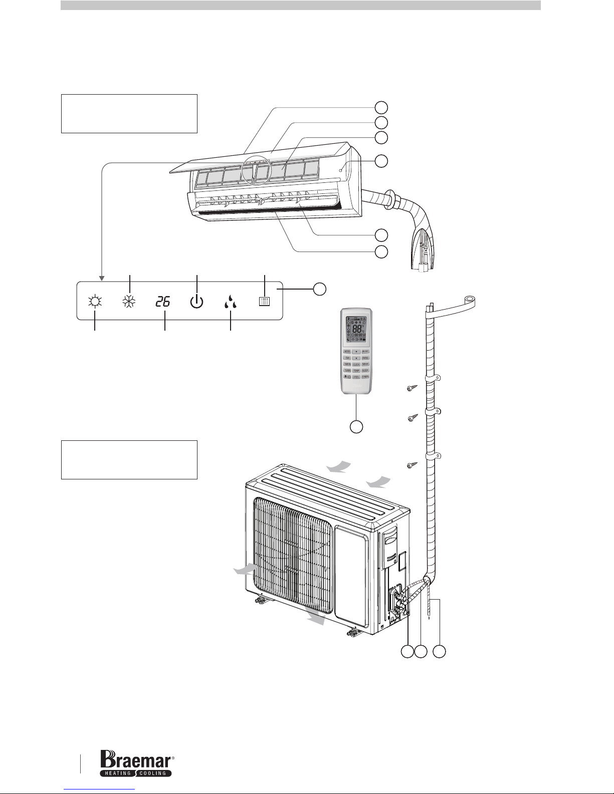
BUTTONS
¹
¹
BSHVD1S Series High Wall Inverter Unit
.
AUTO
SEELEY INTERNATIONAL – OWNER’S MANUAL 7
OPERATION cont.
TIMER SETTINGS
TIMER ON
The unit can be programmed to turn
on, turn off or a combination of both
when in standby or power ON modes.
Use the below settings.
Press the button to enter
the setup. The icon will disappear
and “ON”will blink on the remote
controller display. Use the
TIMER ON
icon will be displayed.
Press the TIMER OFF button to enter
the setup. The icon will disappear
and “OFF”will blink on the remote
controller display. Use the
icon will be displayed.
¹
▲ ▼
▲ ▼
or
buttons to adjust the clock time for the
unit to start. Holding these buttons will
produce rapid adjustment.
When complete, press the TIMER ON
button again to set - “ON”will stop
blinking and
Pressing the TIMER ON button again
will CANCEL the TIMER ON function.
or
buttons to adjust the clock time for the
unit to stop.
When complete, press the TIMER OFF
button again to set - “OFF”will stop
blinking and
Pressing the TIMER OFF button again
will cancel the TIMER OFF function.
¹
¹
¹
TIMER OFF
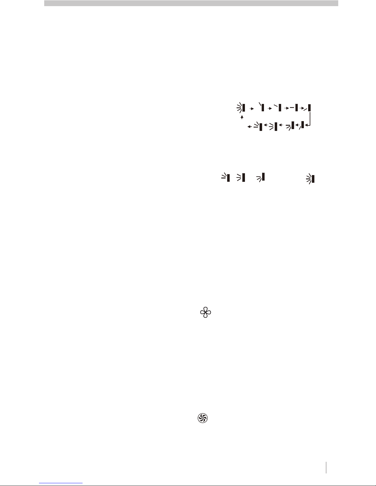
SWING UP / DOWN
Press to adjust the UP/DOWN louvre,
each press will toggle between the
below settings:-
Where a single line indicates a fixed
position, multiple lines indicate
swinging up/down in the positions
shown. This remote is universal -
select , or will act as
If the louvre is set to OFF (no display)
when swinging, it will remain fixed in
the last position.
X-FAN
TURBO
The X-FAN function can be used in
COOL or DRY modes, so as to
continue operation of the indoor fan for
an additional 2 minutes after the power
is turned off (so as to remove excess
moisture from the indoor coil). The
icon will be displayed.
Default setting is X-FAN ‘OFF’, and is
not available in AUTO, FAN or HEAT
modes.
When the unit is first turned on in
COOL or HEAT modes, press TURBO
to quickly reach the SET temperature.
will be shown on the remote
controller display. Press this button
again to exit TURBO function.
OFF


 null")