OPERATION cont.
I FEEL
Press the I FEEL button to activate this
feature. The remote controller will act
as the temperature thermostat,
sending a temperature reading to the
unit every 10 minutes. By this method,
the unit will react to where the remote
controller is positioned. I FEEL will be
shown on the remote controller
display.
Press the I FEEL button again to
this feature.
Press SLEEP button to toggle between
the SLEEP modes and cancel, as
described below. Default setting is
SLEEP mode ‘OFF’:-
In COOL and DRY modes,
after running for one hour, the main
unit SET temperature will increase by
1°C, then after 2 hours will increase by
2°C, then will continue to run at this
temperature.
cancel
SLEEP
SLEEP 1:
In HEAT mode, the SET temperature
will decrease by 1°C and then 2°C for
the first 2 hours, and then stay
constant.
In COOL mode, the SET
temperature will vary according to the
below scenarios:-
a) If SET temperature starts between
16-23°C, SET temperature will
increase by 1°C every hour for 3
hours, then stay constant until 7 hours
SLEEP 2:
SLEEP cont.
has elapsed. It will then be decreased
by 1°C, then will continue to run at this
temperature.
b) If SET between 24-27°C, SET
temperature will increase by 1°C every
hour for 2 hours, then stay constant
until 7 hours has elapsed. It will then
be decreased by 1°C, then will
continue to run at this temperature.
c) If SET between 28-29°C, SET
temperature will increase by 1°C for 1
hour, then stay constant until 7 hours
has elapsed. It will then be decreased
by 1°C, then will continue to run at this
temperature.
d) If SET at 30°C, SET temperature
will stay constant until 7 hours has
elapsed. It will then be decreased by
1°C, then will continue to run at this
temperature.
In HEAT mode:-
a) If SET at 16°C, it will remain at this
temperature.
b) If SET between 17-20°C, SET
temperature will decrease by 1°C for 1
hour, then will continue to run at this
temperature.
c) If SET between 21-27°C, SET
temperature will decrease by 1°C for 2
hours, then will continue to run at this
temperature.
SLEEP cont.
d) If SET between 28-30°C, SET
temperature will decrease by 1°C for 3
hours, then will continue to run at this
temperature.
this is a User programmable
curve, created as follows:-
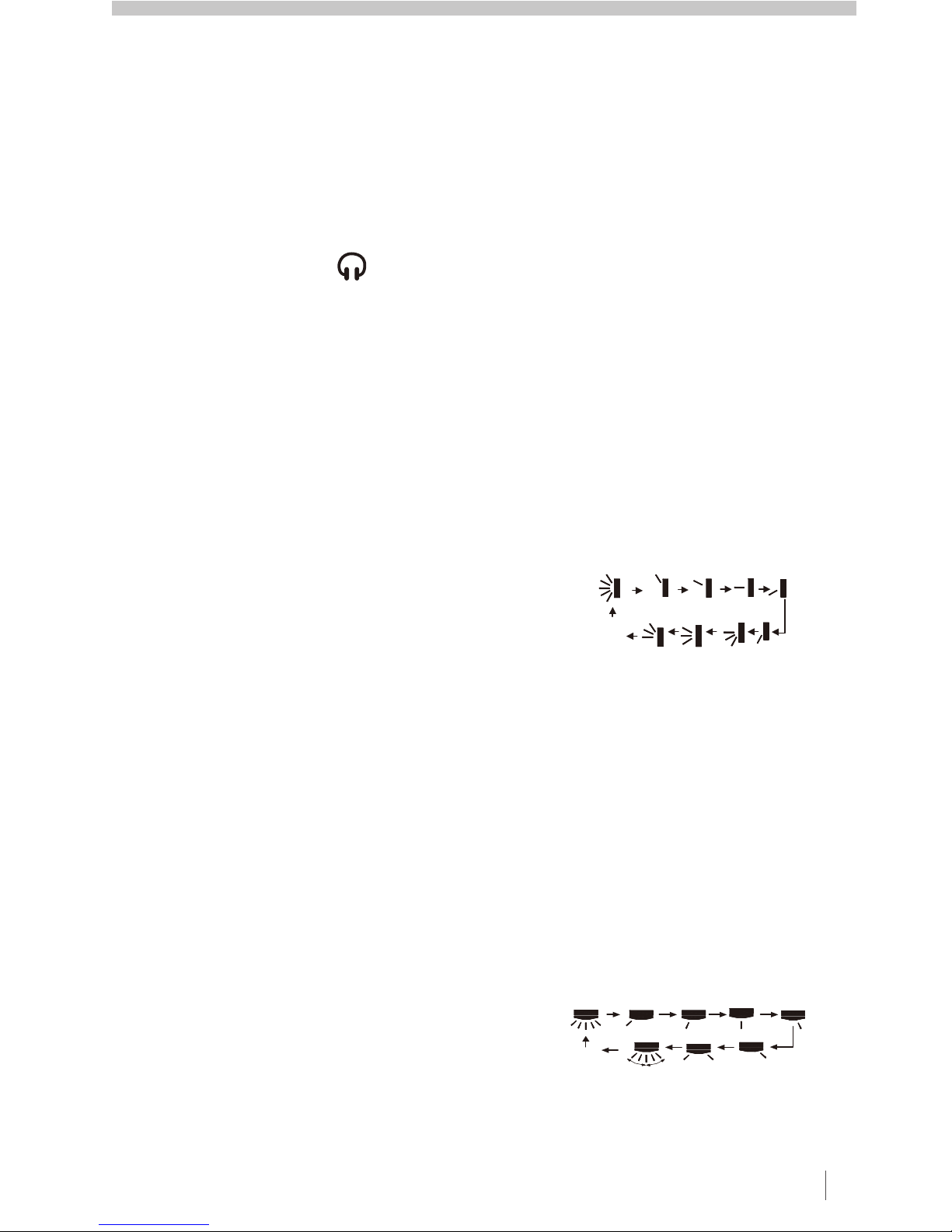
a) When in SLEEP 3 mode, hold the
TURBO button down until the remote
displays ‘1 hour’and the SET
temperature will display.
b) Adjust the SET temperature, then
press TURBO button to confirm.
c) The remote display will move to the
next time setting (’2 hours’,‘3 hours’or
‘8 hours’), and the SET temperature
can agin be programmed.
d) Repeat until the ‘8 hours’SET
temperature has been entered. Once
completed, the remote display will
show the original settings.
The SLEEP 3 settings will be stored
and can be reviewed at any time in the
SLEEP 3 mode by pressing the
TURBO button and scrolling through
without adjusting the settings.
Review mode will be quit if no button is
pressed within 10 seconds, or if the
ON/OFF, MODE, TIMER or SLEEP
buttons are pressed.
SLEEP 3:
8
OPERATION cont.
SEELEY INTERNATIONAL – OWNER’S MANUAL 9
LOCK
The remote controller can be locked
from inadvertent button operation.
Press both ▲ ▼
▼
or buttons
simultaneously to lock (or unlock) the
remote controller. The icon will be
displayed, and will flicker when a
button is pressed.
The temperature display can be
toggled between Centigrade and
Fahrenheit scales by pressing the
MODE and buttons simultaneously.
FAHRENHEIT / CENTIGRADE
ENERGY SAVING
When in COOL mode, press the TEMP
and CLOCK buttons simultaneously to
start Energy Saving function. The
remote controller display will show the
‘SE’icon. Repeat to cancel.
When in HEAT mode, press the TEMP
and CLOCK buttons simultaneously to
start 8°C Heating function. The
remote display will show and a
selected temperature of ‘8°C’(46°F).
Repeat to cancel.
8°C HEATING FUNCTION
MSHV Series High Wall Inverter UnitD1S


 null")