Braga Moro Aquarius Plus User manual

UNI EN ISO 9001-2015 n° 9115.BRMO
USER MANUAL
“Aquarius Plus”
File name Date Page
Code
PUT9I001 PUT9I1K5
DF19009A 05/04/19 1 di 32 PUT9I002
PUT9I003
MD03006C - All rights are reserved according to the law. Reproducing or distributing this document to third parties without permission is prohibited.
BRAGA MORO
SISTEMI DI ENERGIA S.p.A
VIA LUDWIG VAN BEETHOVEN N.24
20092 CINISELLO BALSAMO (MI)
Tel.: +39 02 51 67 22 01
Fax: +39 02 51 67 22 13
mailto:sales@bragamoro.com
www.bragamoro.com
USER MANULA
“AQUARIUS PLUS”
Da 1KVA a 3KVA
Cosphi 0,9

UNI EN ISO 9001-2015 n° 9115.BRMO
USER MANUAL
“Aquarius Plus”
File name Date Page
Code
PUT9I001 PUT9I1K5
DF19009A 05/04/19 2 di 32 PUT9I002
PUT9I003
MD03006C - All rights are reserved according to the law. Reproducing or distributing this document to third parties without permission is prohibited.
1. DOCUMENT CHECK SECTION
Drawing
Written by
Role Date
Alessandri David Technical Staff
29-03-17
Control
Control by
Role
Date
Alessandri David Technical Staff 29-03-17
Approved
Approved by Role Date
Abbondio Adelio Technical Staff 29-03-17
Revision
Rev.
Author
Descr
iption
Date
B
C
D
E
F
G
H
I
L
References
Ref. Author Title Revision

UNI EN ISO 9001-2015 n° 9115.BRMO
USER MANUAL
“Aquarius Plus”
File name Date Page
Code
PUT9I001 PUT9I1K5
DF19009A 05/04/19 3 di 32 PUT9I002
PUT9I003
MD03006C - All rights are reserved according to the law. Reproducing or distributing this document to third parties without permission is prohibited.
1. Preface
Thank you for purchasing our UPS, it is safe and reliable, little maintenance is required.
Read this manual carefully and completely. It includes safety and operating installation instructions.
It will help your UPS get a longer service life. This manual explains the principle of internal
operation, and the related protection functions.
This manual also contains information on the use of the equipment.
Please respect the instructions and all the warnings indicated in the manual or on the machine. Do
not use the machine before completing the safety reading and the operating instructions.
Note: due to continuous improvements, our products may differ from the contents included in this
manual. You can contact the local office to get information when needed.

UNI EN ISO 9001-2015 n° 9115.BRMO
USER MANUAL
“Aquarius Plus”
File name Date Page
Code
PUT9I001 PUT9I1K5
DF19009A 05/04/19 4 di 32 PUT9I002
PUT9I003
MD03006C - All rights are reserved according to the law. Reproducing or distributing this document to third parties without permission is prohibited.
General index
1. DOCUMENT CHECK SECTION ............................................................................................................. 2
1. Preface .................................................................................................................................................... 3
1 Description ............................................................................................................................................... 5
2 Safety Instructions ................................................................................................................................... 7
3 Product presentation ............................................................................................................................... 8
4 Installation ............................................................................................................................................. 11
5 Display operation and management ...................................................................................................... 15
6 Maintenance .......................................................................................................................................... 25
7 TROUBLESHOOTING .......................................................................................................................... 25
8 Reference standards ............................................................................................................................. 30
9 Electrical characteristics ........................................................................................................................ 30
10 Environmental conditions ...................................................................................................................... 31
11 Mechanical specifications Rack mounting 19” ...................................................................................... 31
12 Communication ports............................................................................................................................. 31

UNI EN ISO 9001-2015 n° 9115.BRMO
USER MANUAL
“Aquarius Plus”
File name Date Page
Code
PUT9I001 PUT9I1K5
DF19009A 05/04/19 5 di 32 PUT9I002
PUT9I003
MD03006C - All rights are reserved according to the law. Reproducing or distributing this document to third parties without permission is prohibited.
1 Description
UPS (Uninterruptible Power Supply) is a device that allows continuity in the supply of loads in
alternating current, but also has protection and monitoring functions. The UPS plays a very
important role in the supply of computers and the computer network to which the computer is
possibly connected. The fields of application of UPS are numerous: communication, finance,
electricity, transport, national defense, universities, scientific research institutes and so on.
The Aquarius series from 1KVA to 3kVA, are products designed with the advanced ON-LINE UPS
technology, which provide the user with multiple functions and good performance.
1.1 Functions and features
1. The latest generations of IGBTs have been used in our UPSs to provide reliability and high
performance. In general, the electronic components we have used are able to work normally for
more than 300,000 hours.
2. Using digital technology associated with reliable algorithms, we have been able to create a
powerful and easy-to-use product.
3. The self-test at the start-up of the apparatus, allows to find in advance, potential problems of the
UPS in order to be able to intervene and resolve the problem promptly.
4. The on-line double conversion topology means that in the UPS output there is a sine wave with
constant voltage and frequency, low noise and without any type of interruption of energy supplied
to the load. All this guarantees the correct functioning of the equipment powered by our UPSs.
5. The transfer time between the main source and the emergency source at the UPS exit is zero, when
the main power supply fails it is immediately replaced by the emergency power supply
6. With the bypass function incorporated in the UPS, the energy is transferred to the loads without
any interruption. This feature is very useful when you need to perform maintenance on the UPS.
7. Advanced voltage compensation technology leads to having the input voltage range from 115V to
295V, which reduces battery usage and improves the ability to adapt to changing network
conditions.
8. The AC input frequency is 50Hz / 60Hz. When the output frequency is 50Hz, the AC input frequency
range is 45Hz-55Hz, when the output frequency is 60Hz, the AC input frequency range is 55Hz-
65Hz. The UPS has good compatibility with generators. It is suitable for different types of single-
phase generators.
9. The advanced PFC (Power Factor Correction), a technology that leads to a power factor higher than
0.98 of the UPS, increasing its energy efficiency and removing harmonic distortion.
10. The UPS starts up in battery mode, to be able to power the loads even in the absence of the mains.
When the battery voltage is low, the UPS protects itself and turns off automatically. When the main
power is restored, the UPS will detect its presence, checking that the voltage and frequency are in
the ranges. Once the input voltage is considered good, the UPS will automatically turn on to supply
loads; if the network is not considered good, the UPS will still start the charger to recharge the

UNI EN ISO 9001-2015 n° 9115.BRMO
USER MANUAL
“Aquarius Plus”
File name Date Page
Code
PUT9I001 PUT9I1K5
DF19009A 05/04/19 6 di 32 PUT9I002
PUT9I003
MD03006C - All rights are reserved according to the law. Reproducing or distributing this document to third parties without permission is prohibited.
battery. In this case the group does not switch on to supply loads until the voltage and frequency of
the main source fall within the allowed ranges.
11. When there is no power supply, the UPS can be started by battery. This feature is called cold start
and is used to supply loads in emergencies. This feature can also be activated at full load.
12. The UPS intervenes to protect the load when the following events occur: When the main input or
output power is too high or too low, in case of overload, short circuit, high inverter stage
temperature, minimum voltage and battery overload.
13. The UPS can be installed in a Rack or Tower version. The viewing angle of the display can be easily
changed by pressing two buttons on the control panel of the apparatus. The content displayed on
the interface is rich in measurements. Alarms and statuses are easily controlled from the operator
panel.
14. It is possible to connect the UPS to a computer, through an RS232 serial port. A software must be
installed on the PC that allows the intelligent management of most of the functionalities of the
device.
15. If you want to connect the UPS to a computer network, you must have a kit called "SNMP adapter".
The connection can be internal or external to the UPS. Through these cards it is possible to monitor
the UPS from the internet or by evicting the various network protocols made available to the kit.
16. A further possibility to monitor the UPS is the USB port, present on the UPS. Also, in this case it will
be necessary to load a software on the PC to which the group is connected.
17. The ECO function saves electricity. When the input voltage is in an acceptable range, the load is fed
directly from the mains. In this case the inverter remains in stand-by. When the input voltage
comes out of the ranges, the load is powered by the inverter, which returns the output voltage in
the allowed ranges.
UNI EN ISO 9001-2015 n° 9115.BRMO
USER MANUAL
“Aquarius Plus”
File name Date Page
Code
PUT9I001 PUT9I1K5
DF19009A 05/04/19 7 di 32 PUT9I002
PUT9I003
MD03006C - All rights are reserved according to the law. Reproducing or distributing this document to third parties without permission is prohibited.
2 Safety Instructions
This chapter mainly introduces safety marks and notes on the 1KVA-3KVA online UPS series.
Read this chapter carefully before using the equipment.
2.2 Safety
There are dangerous voltages and high temperatures inside the UPS. During the installation
and maintenance operation, please follow the safety instructions in the interior and the relevant laws,
otherwise personal injury or damage to the equipment may occur. Safety instructions in this text are
like an additional manual for internal safety instructions. Our company does not assume the
responsibility caused by non-compliance with safety instructions. Please note the following:
1. Do not use the UPS when the actual load exceeds the nominal load.
2. There are high-capacity batteries in standard-type UPSs. Do not open the cover. There is
a danger of electric shock. In case of maintenance or replacement of the internal battery,
please send it to the nearest UPS service center.
3. A short circuit inside the UPS causes electric shock or possible fire. Therefore, do not place
containers with liquid on top of the UPS so as not to cause danger of electric shock.
4. Do not put the UPS in a place with high temperature or humidity, as well as corrosive gases
and a lot of dust.
5. Maintain good air circulation on the front panel and rear panel.
6. In case of smoke coming out of the UPS, please remove the power as soon as possible
and contact the assistance service.
2.3 Indication symbols
The safety symbols mentioned in this manual are shown in the following table. They are used to
inform the user of safety problems that must be respected during installation, operation and
maintenance.
Indication symbols Indication
Attention
Sensitive to electrostatic discharge
Electrocution
There are three levels of security: Dangerous, warning and attention. The meaning is to the right of
the safety symbol, the description is below, as shown below:

UNI EN ISO 9001-2015 n° 9115.BRMO
USER MANUAL
“Aquarius Plus”
File name Date Page
Code
PUT9I001 PUT9I1K5
DF19009A 05/04/19 8 di 32 PUT9I002
PUT9I003
MD03006C - All rights are reserved according to the law. Reproducing or distributing this document to third parties without permission is prohibited.
Dangerous:
Indicates the risk of serious injury or death or serious damage to the equipment
Attention:
Indicates the risk of serious injury or damage to the equipment.
Warning:
Indicates risk of injury or equipment damage.
3 Product presentation
3.1 Product appearance
Illustration 1: front panel
UNI EN ISO 9001-2015 n° 9115.BRMO
USER MANUAL
“Aquarius Plus”
File name Date Page
Code
PUT9I001 PUT9I1K5
DF19009A 05/04/19 9 di 32 PUT9I002
PUT9I003
MD03006C - All rights are reserved according to the law. Reproducing or distributing this document to third parties without permission is prohibited.
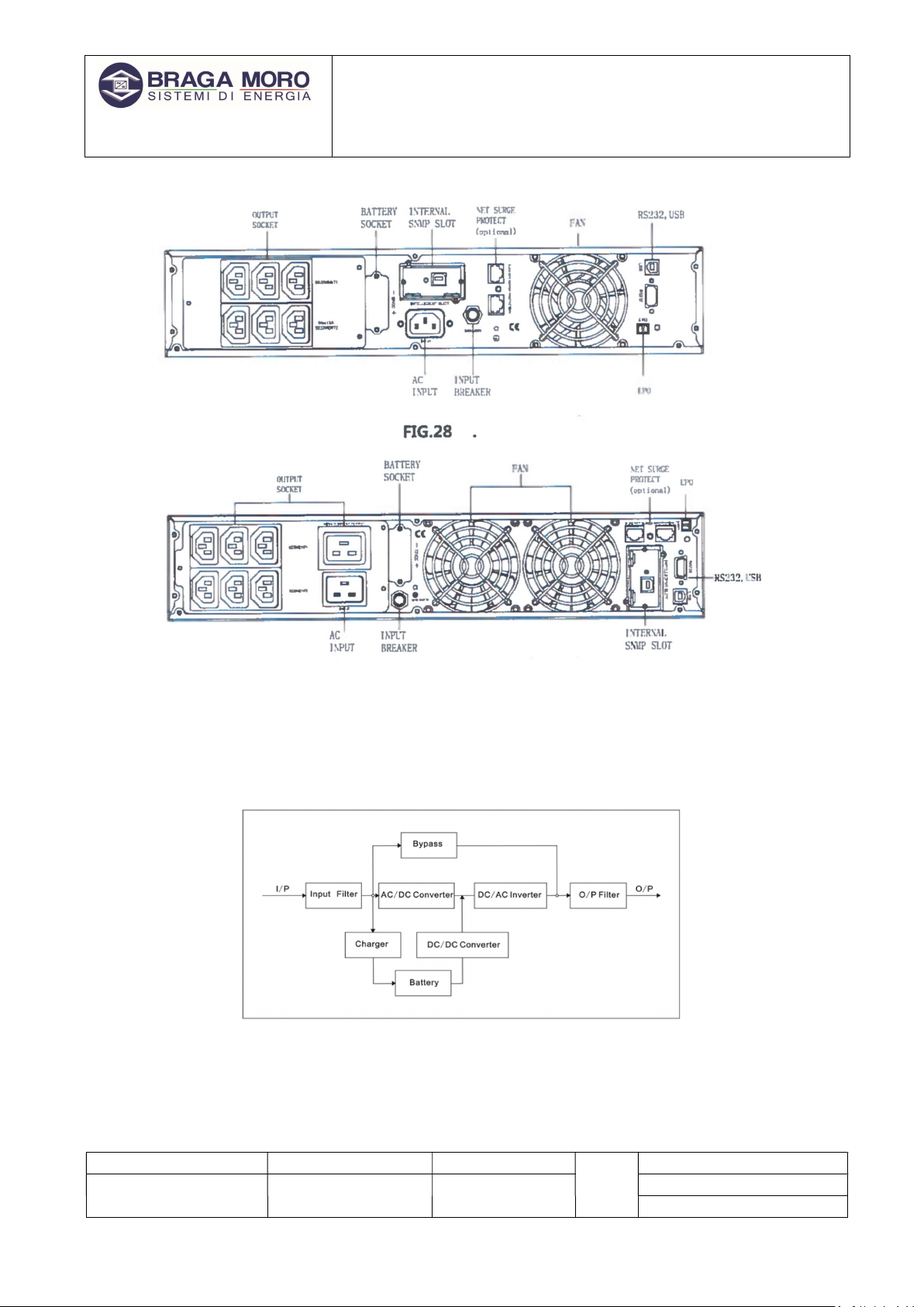
Illustration 2: Rear panel
3.2 The principle of the product
Illustration 3: Principle outline

UNI EN ISO 9001-2015 n° 9115.BRMO
USER MANUAL
“Aquarius Plus”
File name Date Page
Code
PUT9I001 PUT9I1K5
DF19009A 05/04/19 10 di 32 PUT9I002
PUT9I003
MD03006C - All rights are reserved according to the law. Reproducing or distributing this document to third parties without permission is prohibited.
1. Input filter: filters the AC mains input supply to supply clean energy for the UPS.
2. AC / DC converter: Converts the filtered mains voltage (AC) into DC voltage and elevates it
for the DC / AC inverter.
3. DC / DC booster: When the UPS is operating in battery mode, this circuit increases the DC
voltage for the inverter.
4. DC / AC inverter: Converts the direct voltage (DC) to a stable alternating voltage (AC)
output.
5. Bypass: When an overload or failure of the inverter occurs, the UPS goes into bypass
mode to supply loads.
6. Charger: the standard unit provides 1A, while the long-life charger provides 4A.
7. Battery: sealed lead acid batteries.
8. Output Filter: Completely filters the UPS output to provide clean energy for the loads.
3.3 Modell
UPS type MODEL NO Remark
Standard unit
1KVAS Internal battery charger
1A,2
batterie
PCS
7AH
2KVAS Internal battery charger
1A,4
batterie
PCS
7AH
3KVAS Internal battery charger
1A,6
batterie
PCS
7AH
Table 1: Aquarius model
To request an expansion battery box, for long term backup contact the Braga Moro sales office, or
write to the following E-Mail address: sales@bragamoro.com

UNI EN ISO 9001-2015 n° 9115.BRMO
USER MANUAL
“Aquarius Plus”
File name Date Page
Code
PUT9I001 PUT9I1K5
DF19009A 05/04/19 11 di 32 PUT9I002
PUT9I003
MD03006C - All rights are reserved according to the law. Reproducing or distributing this document to third parties without permission is prohibited.
4 Installation
4.1 Unpacking and inspection
1. Unpack the UPS and check that there is no damage caused during transport. If any parts
are damaged or missing, do not start the appliance and inform the carrier and report it to
the service center.
2. Check the attachment (please refer to the Appendix 1 table).
4.2 Note
Please place the UPS in a clean environment and avoid vibration, dust, moisture, flammable
and corrosive gases and liquids.
The ambient temperature must be in a range between 0 ° C ~ 40 ° C. If the ambient
temperature exceeds 40 ° C, the nominal power decreases by 12% as the ambient
temperature increases.
The maximum working temperature cannot be higher than 50 ° C.
The UPS must be placed in a sufficiently ventilated place.
4.3 Mounting the brackets for the Tower-mounted installation
The plastic brackets must be mounted as shown in illustration 5 and 6
As for the mounting of the brackets for the different UPS models, it is necessary to know that the
1KVA unit needs a space of 1 unit, so it is sufficient to follow the illustrations 5 and 6. For the other
models the space between the brackets it is 2 units and for a correct assembly the other
illustrations in this paragraph must also be considered.
Illustration 4: mounting brackets
-
1
Illustration 5: mounting brackets
-
2

UNI EN ISO 9001-2015 n° 9115.BRMO
USER MANUAL
“Aquarius Plus”
File name Date Page
Code
PUT9I001 PUT9I1K5
DF19009A 05/04/19 12 di 32 PUT9I002
PUT9I003
MD03006C - All rights are reserved according to the law. Reproducing or distributing this document to third parties without permission is prohibited.
Illustration 6:
mounting brackets
for
2/3KVA
UNI EN ISO 9001-2015 n° 9115.BRMO
USER MANUAL
“Aquarius Plus”
File name Date Page
Code
PUT9I001 PUT9I1K5
DF19009A 05/04/19 13 di 32 PUT9I002
PUT9I003
MD03006C - All rights are reserved according to the law. Reproducing or distributing this document to third parties without permission is prohibited.
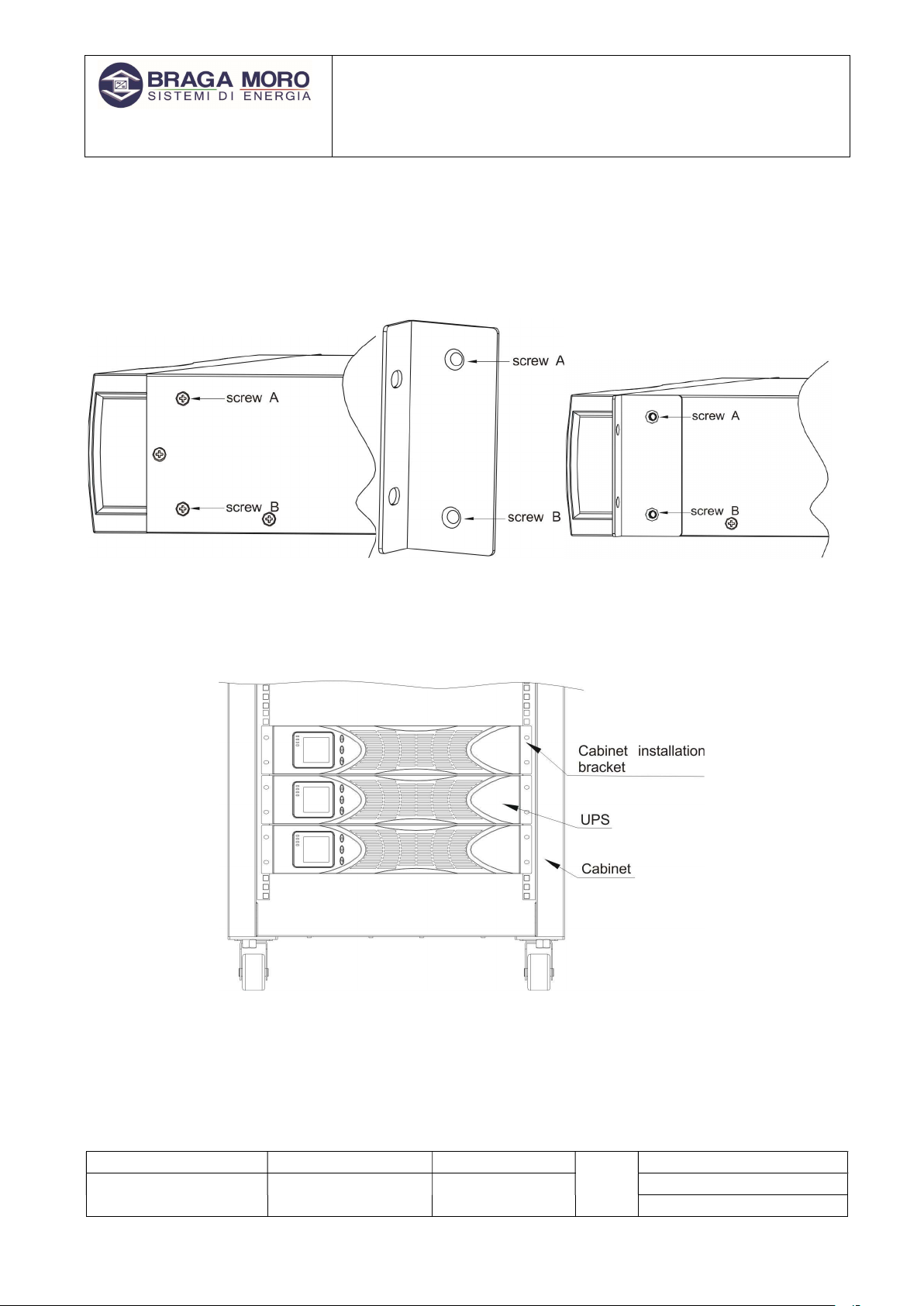
4.4 Mounting of rack mounting brackets
The following illustrations show how to fix the brackets on the groups, to perform a rack mount.
The screws (SCREW A and B) shown in illustration 9 are from M4.
The fixing of the brackets must be carried out on both sides of the UPS.
Illustration 3: Fixing brackets for rack
mounting
Illustration 4: Fixing
bracket
Illustration 5: Fixing bracket on
UPS
Illustration
6
: Rack mounting
UNI EN ISO 9001-2015 n° 9115.BRMO
USER MANUAL
“Aquarius Plus”
File name Date Page
Code
PUT9I001 PUT9I1K5
DF19009A 05/04/19 14 di 32 PUT9I002
PUT9I003
MD03006C - All rights are reserved according to the law. Reproducing or distributing this document to third parties without permission is prohibited.
4.5 UPS output input connection
the UPS to the mains and to the loads with the supplied power cable.
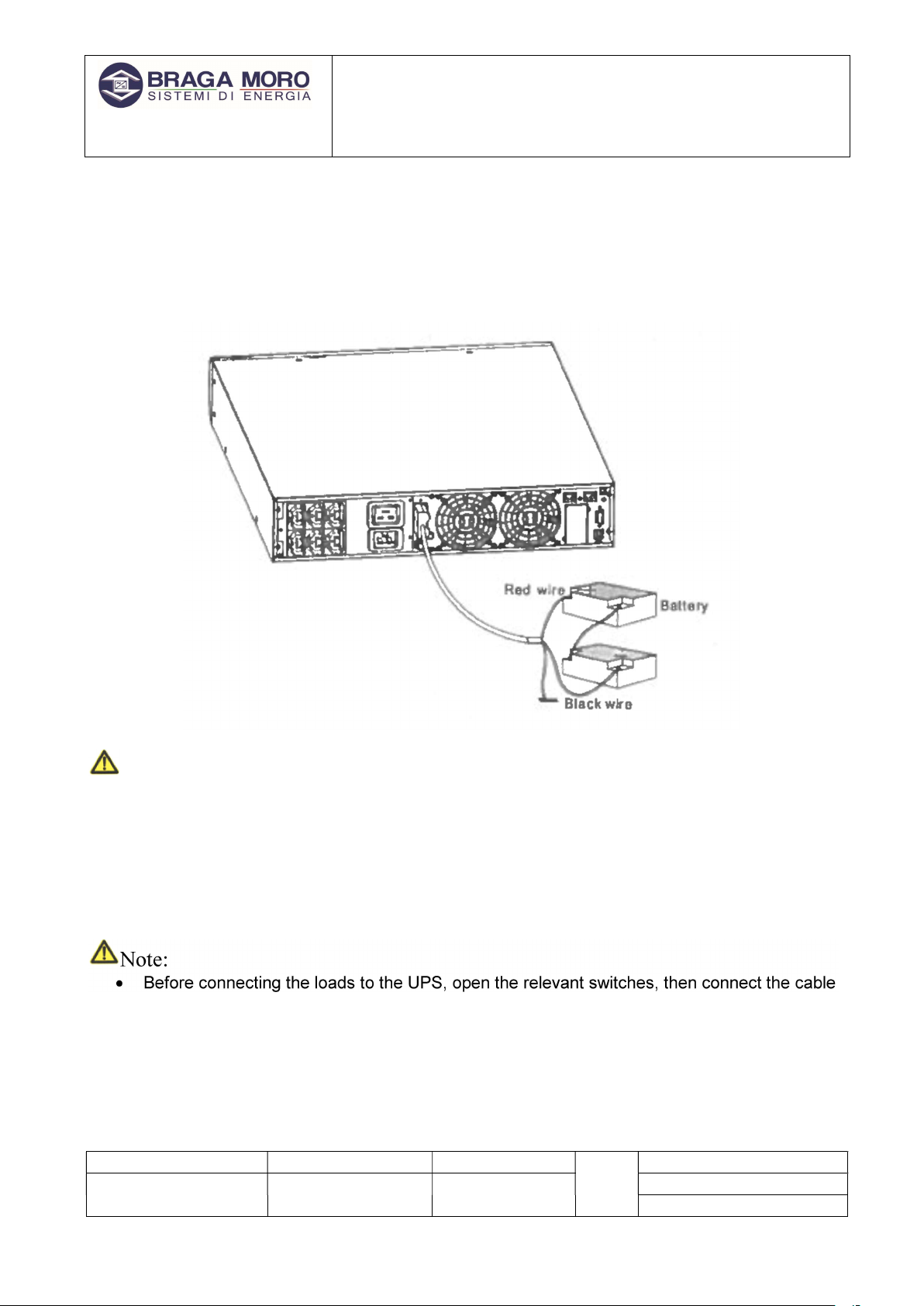
4.6 Connection to the high autonomy battery box
Attention:
Before installing the battery, make sure the UPS is turned off and its switch is open. Use all
the precautions dictated by the safety rules at work, in order to avoid accidents.
Pay attention to the battery polarity. The red cable connects it with the positive of the
battery "+" and black cable connect it with the negative "-".
Please use insulated tools that comply with the occupational safety directives. Do not place
instruments or metal objects on the battery.
Note:
Before connecting the loads to the UPS, open the relevant switches, then connect the cable
to power supply and finally turn on the loads one at a time.
To avoid damage, it is strictly forbidden to connect inductive loads such as motors,
fluorescent lamps and photocopiers to the UPS.
Connect the UPS to a device with overcurrent protection. The socket used must have a
ground connection.

UNI EN ISO 9001-2015 n° 9115.BRMO
USER MANUAL
“Aquarius Plus”
File name Date Page
Code
PUT9I001 PUT9I1K5
DF19009A 05/04/19 15 di 32 PUT9I002
PUT9I003
MD03006C - All rights are reserved according to the law. Reproducing or distributing this document to third parties without permission is prohibited.
The UPS can supply output voltage regardless of whether the power cord is connected to
the power outlet. If you want the UPS not to supply output voltage, first open the circuit-
breaker and then detach the network.
When connecting the laser printer, select the pickup capacity at the UPS start according to
the UPS model in order to have more power at start-up.
5 Display operation and management
Operation is simple. operators must only read the manual and follow the operating instructions
contained in this without any special training.
5.1 Button operation:
Buttons ON ( + )
Press these two buttons for more than half a second to turn on the UPS.
Buttons OFF ( + )
Press these two buttons for more than half a second to turn off the UPS.
TEST/MUTE buttons (+ )
Press the keys for more than 1 second in line mode or in economic mode: the UPS will perform
the auto test function.
Press the keys for more than 1 second in battery mode: the UPS performs the mute function.
Search keys o
Consultation method:
Press the keys for more than half a second (less than 2 seconds): list in order of the items
of the LCD display.
Press and hold these keys for more than 2 seconds: the display rotates 90 ° displays the
items every 2 seconds, keeping the keys pressed for the same amount of time, turn back to
the initial position.
Mode setting function:
Press and hold the button for more than half a second (less than 2 seconds):
Select the option to be set.
Illustration
7
: front buttons
UNI EN ISO 9001-2015 n° 9115.BRMO
USER MANUAL
“Aquarius Plus”
File name Date Page
Code
PUT9I001 PUT9I1K5
DF19009A 05/04/19 16 di 32 PUT9I002
PUT9I003
MD03006C - All rights are reserved according to the law. Reproducing or distributing this document to third parties without permission is prohibited.
Key setting function
Consultation mode:
Press and hold this key for more than 2 seconds: interface setting function.
Mode setting function:
Press the button for more than half a second (less than 2 seconds): Confirms the set option.
Press the button for more than 2 seconds to exit this interface with the setting function.
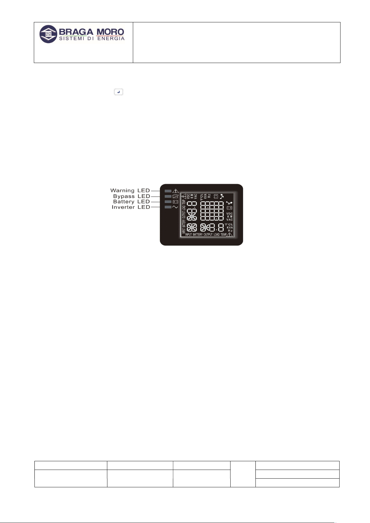
5.2 Function of the LED indicators
Warning Red LED is on: UPS is faulty. For example: overload beyond the allowed time,
inverter failure, BUS failure, high temperature, etc.
Bypass Yellow LED on: UPS is in alarm. For example: active bypass, etc.
Battery Yellow LED on: UPS is in alarm. For example: battery inverter power supply mode.
Inverter Green LED on: UPS is normally powered from the mains or in ECO mode or in battery
mode.
When the UPS starts up, the four LEDs light up and go off one at a time. This sequence
repeats several times until the UPS has finally started up.
NOTE: Regarding the indication of the LEDs in different modes, please refer to the LED
display panel and the warning table.
5.3 Functions of the LCD display
The LCD display appears as shown in the figure:
Illustra
tion
8
: Display

UNI EN ISO 9001-2015 n° 9115.BRMO
USER MANUAL
“Aquarius Plus”
File name Date Page
Code
PUT9I001 PUT9I1K5
DF19009A 05/04/19 17 di 32 PUT9I002
PUT9I003
MD03006C - All rights are reserved according to the law. Reproducing or distributing this document to third parties without permission is prohibited.
LCD display includes a section with numerical values, a graphic section of the power supplied, a
graphic section of the fan status and a graphic section of the battery status.
The numerical values section displays: the input voltage and frequency, the output voltage and
frequency, the output powers, the temperature, the voltage and the percentage of battery charge,
for example, as shown in the figure above, the output voltage is 220V, the output frequency is
50Hz.
Graphic section of battery capacity and load: each box represents 20% of capacity.
As shown in the figure above, the battery capacity is between 80% and 100% (5 panels), the load
is between 40% and 60% (3 panels). When the UPS is overloaded, the icon will flash, when the
battery capacity is too low or disconnected, the icon will flash.
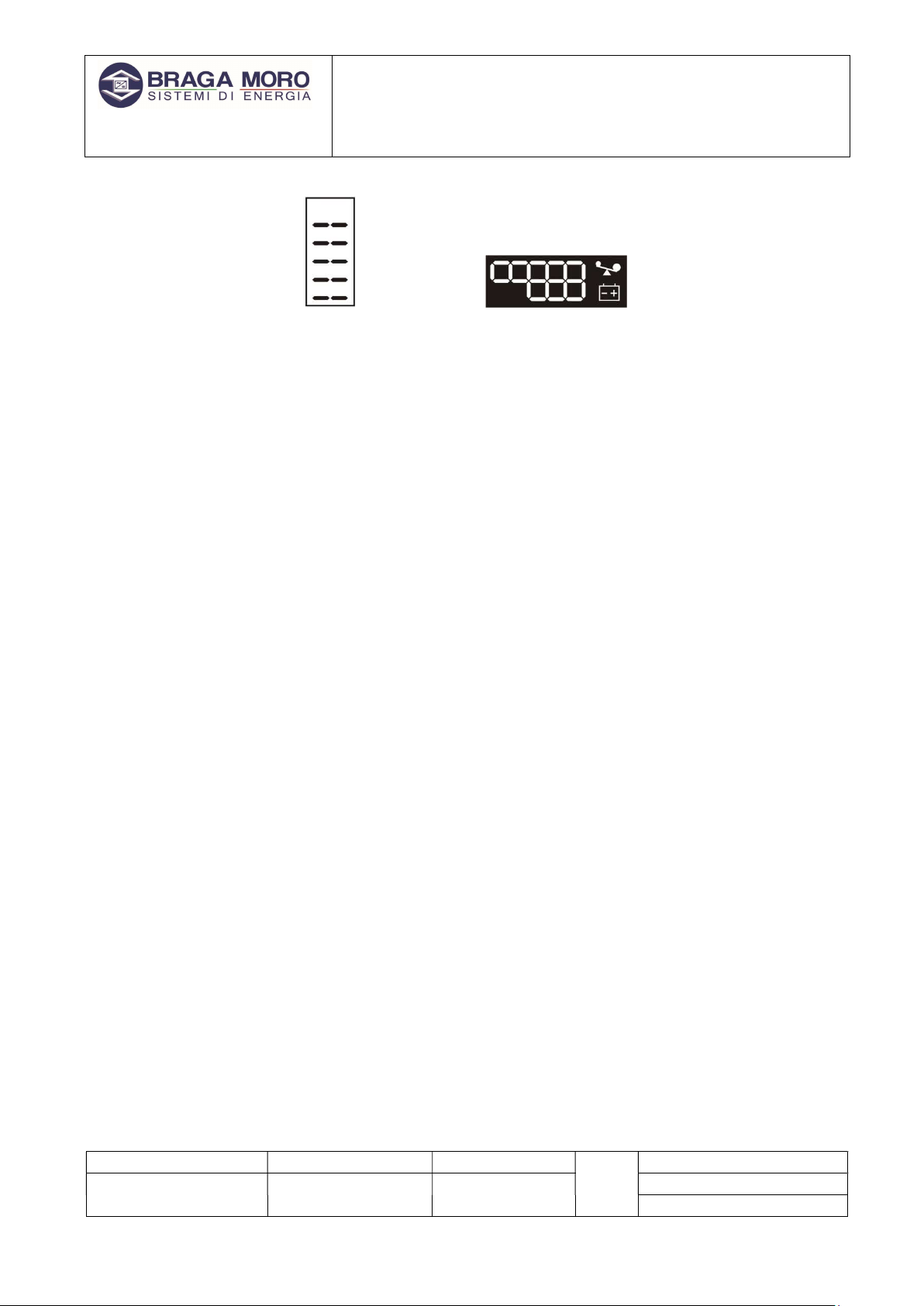
Fan – Defines the fan status. In case the fan is working properly, the graph simulates the rotation
of a propeller. In the event of an anomaly, the fan symbol will begin to flash.
Charger – When the charger is working properly, its symbol will follow a pattern like that shown in
the following figure.
In the event of a malfunction, the symbol will start to flash. When the UPS is in battery mode, the
number of charging status icons will vary depending on the battery capacity. For example: if there
are five boxes (as in the figure below), the corresponding number of lines is five lines (like the
following image on the left).
Illustration 9: Example
screen
UNI EN ISO 9001-2015 n° 9115.BRMO
USER MANUAL
“Aquarius Plus”
File name Date Page
Code
PUT9I001 PUT9I1K5
DF19009A 05/04/19 18 di 32 PUT9I002
PUT9I003
MD03006C - All rights are reserved according to the law. Reproducing or distributing this document to third parties without permission is prohibited.
5.4 operation
5.4.1 UPS start-up
Starting the UPS, the Line Mode.
Once the mains supply is connected, the UPS charges the batteries. The display will show that the
output voltage is 0, which means that UPS cannot yet power the load. If you plan to use the bypass,
you can set the bps "ON" from the LCD settings menu.
To start the UPS, hold down the ON button for more than half a second. When the time expires the
inverter will start up.
Once started, the UPS will perform a self-test. The LEDs will turn on and off in a circular and orderly
manner. At the end of the initial test the device will be active and the Line Mode, with the relative
LED lit.
Starting the UPS in battery mode.
To start the UPS even in the absence of mains, keep the ON key pressed for more than half a
second. When the time expires, the inverter will start up.
The start-up of the group is identical to the Line Mode, at the end of the self-test the Battery Mode
LED will light up.
5.4.2 Turn off the UPS
To turn off the UPS, press and hold the OFF button for more than half a second. When the time
expires, the UPS and inverter will shut down.
After switching off the inverter there will be no output voltage left. In this situation it is possible to
activate the by-pass (bps on) function to equally power the load.
The same shutdown procedure, it is possible to use it even when the group is in absence of network
in battery mode.
UNI EN ISO 9001-2015 n° 9115.BRMO
USER MANUAL
“Aquarius Plus”
File name Date Page
Code
PUT9I001 PUT9I1K5
DF19009A 05/04/19 19 di 32 PUT9I002
PUT9I003
MD03006C - All rights are reserved according to the law. Reproducing or distributing this document to third parties without permission is prohibited.
5.4.3 Self-test/Mute modality
By pressing the self-test / mute button for more than one second, the group will start the self-
checking sequence. The LEDs will turn on and off in sequence. During this phase the UPS will check
the quality of its circuits. At the end of the test it will automatically return to the pre-test mode.
In case of pressure of the self-test / Mute for more than one second, when the group is in Battery
Mode, the acoustic signal will be silenced.
5.5 Parameter setting
The UPS allows the modification of some parameters. The changes can be implemented in any
operating mode. The application of the changes made to the group parameters will be checked by
the software of the device before being saved
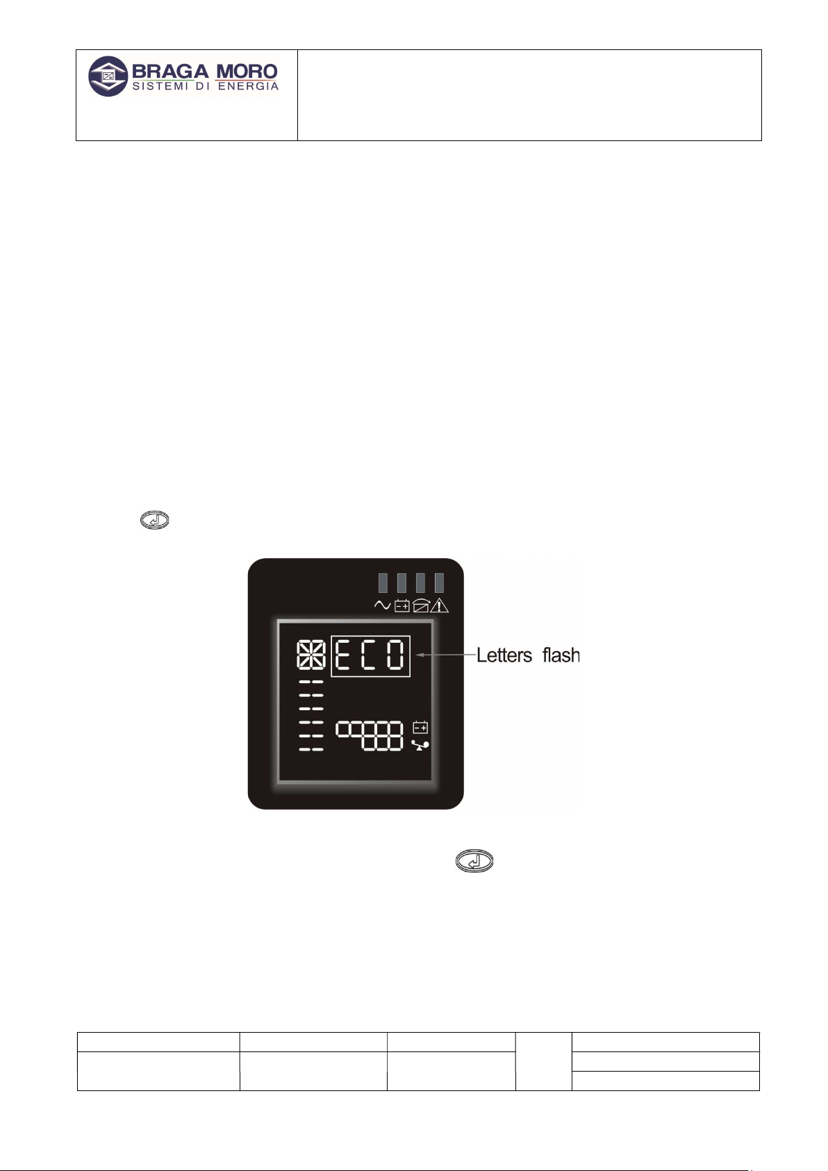
5.5.1 Change UPS parameters.
To access the modification of the UPS configuration parameters, keep the key pressed for two
seconds . Once the mode is activated, the word ECO will flash on the display.
To activate ECO mode, the key must be kept pressed for more than half a second (but not
beyond two seconds). When the time expires you will see ON flashing (see next illustration).
Illustration
10
: Display
-
ECO

UNI EN ISO 9001-2015 n° 9115.BRMO
USER MANUAL
“Aquarius Plus”
File name Date Page
Code
PUT9I001 PUT9I1K5
DF19009A 05/04/19 20 di 32 PUT9I002
PUT9I003
MD03006C - All rights are reserved according to the law. Reproducing or distributing this document to third parties without permission is prohibited.
Press the button to choose which ECO function to activate. The activated functions have the
word ON, while the non-active functions the word OFF. To activate or deactivate the features, press
the button for two seconds. After confirming the message ON or OFF will stop flashing.
To exit parameter modification, keep the button pressed for at least two seconds .
5.5.2 Bypass configuration
Entering the parameter modification mode as described in the previous paragraph. Select the
function with the key , the Bypass message will flash after selection.
Illustration 11: ECO ON
Illustration
12
: Bypass
Table of contents
Other Braga Moro UPS manuals

Popular UPS manuals by other brands

Ametek
Ametek 420VA manual

Braun Group
Braun Group G10K user manual

Xtreme Power Conversion
Xtreme Power Conversion 20kVA Model User and installation manual

CyberPower
CyberPower CP900EPFCLCD quick start guide

Uninterruptible Power Supplies
Uninterruptible Power Supplies PowerWAVE 3000 user manual

Eaton
Eaton 9PX5KiRTN installation manual
 Series user manual")


