Braga Moro OCTANS PLUS 10k User manual

UNI EN ISO 9001
-
2015 n° 9115.BRMO
UPS OCTANS 10/20kVA 3:1
USER MANUAL
File name Date Page
Code
PUV9E010/15/20-AK
DF19010A 10/04/2019 1 di 28
MD03006C All rights are reserved according to the law. Reproducing or distributing this document to third parties without permission is prohibited.
VIA LUDWING VAN BEETHOVEN N.24
20090 CINISELLO BALSAMO (MI)
Tel.: +39 0251672201
Fax: +39 0251672213
Mail: sales@bragamoro.com
www.bragamoro.com
USER MANUAL
OCTANS PLUS 15/20kVA 3:1

UNI EN ISO 9001
-
2015 n° 9115.BRMO
UPS OCTANS 10/20kVA 3:1
USER MANUAL
File name Date Page
Code
PUV9E010/15/20-AK
DF19010A 10/04/2019 2 di 28
MD03006C All rights are reserved according to the law. Reproducing or distributing this document to third parties without permission is prohibited.
INDEX
1 DOCUMENT CHECK SECTION ............................................................................................................... 3
2 Safety instructions ..................................................................................................................................... 5
2.1 Prohibitions .............................................................................................................................. 5
3 Safety tips ................................................................................................................................................. 5
4 Production Introduction ............................................................................................................................. 6
4.1 Application ............................................................................................................................... 6
4.2 1.2 Product range ..................................................................................................................... 6
4.3 1.3 System principle diagram .................................................................................................... 6
4.4 Features .................................................................................................................................. 7
4.5 Product overview ...................................................................................................................... 7
4.5.1 Product view ..................................................................................................................... 7
4.5.2 Rear panel instruction ....................................................................................................... 8
5 Installation ................................................................................................................................................. 9
5.1 Unpack checking ...................................................................................................................... 9
5.2 Installation procedure ............................................................................................................... 9
5.2.1 Installation note ................................................................................................................ 9
5.2.2 Installation ..................................................................................................................... 10
5.3 Connection of parallel system .................................................................................................. 12
6 Operation ................................................................................................................................................ 13
6.1 Working modes ...................................................................................................................... 13
6.1.1 AC mode ........................................................................................................................ 13
6.1.2 Bypass mode .................................................................................................................. 13
6.1.3 Battery mode .................................................................................................................. 13
6.1.4 ECO mode ...................................................................................................................... 13
6.2 Panel display, operation and running ....................................................................................... 14
6.2.1 Start up and turn off the UPS ........................................................................................... 14
6.2.2 Faceplate display ............................................................................................................ 15
3 Display instruction ...................................................................................................................... 17
6.3 Working Mode and transferring ............................................................................................... 20
6.3.1 Transfer to bypass if overload .......................................................................................... 20
6.3.2 Normal mode to battery mode ......................................................................................... 20
6.3.3 Go to bypass mode due to over temperature .................................................................... 20
6.3.4 Output short circuit ......................................................................................................... 20
6.3.5 Batter self-Test ............................................................................................................... 20
6.4 UPS monitoring ...................................................................................................................... 20
6.5 Display Messages/ Records ..................................................................................................... 20
6.5.1 Operational Status and Mode(s) ....................................................................................... 21
6.5.2 Alarm Information ........................................................................................................... 21
7 Specification ............................................................................................................................................ 23
8 Maintenance ............................................................................................................................................ 25
8.1 Fan maintenance .................................................................................................................... 25
8.2 Battery maintenance ............................................................................................................... 25
8.3 Visual checking ...................................................................................................................... 25
8.4 UPS status checking ............................................................................................................... 25
9 Trouble shooting ..................................................................................................................................... 26
10 Appendix I USB communication port definition ....................................................................................... 27
11 Appendix II RS232 communication port definition .................................................................................. 28

UNI EN ISO 9001
-
2015 n° 9115.BRMO
UPS OCTANS 10/20kVA 3:1
USER MANUAL
File name Date Page
Code
PUV9E010/15/20-AK
DF19010A 10/04/2019 3 di 28
MD03006C All rights are reserved according to the law. Reproducing or distributing this document to third parties without permission is prohibited.
1 DOCUMENT CHECK SECTION
Drawing
Written by Role Date
David Alessandri Technical Staff 10/04/2019
Control
Controlled by Role Date
David Alessandri Technical Staff 10/04/2019
Approved
Approved by Role Date
Adelio Abbondio Technical Staff 10/04/2019
Revision
Rev. Author Description Date
B
C
D
E
F
G
H
I
L
References
Ref. Author Title Revision

UNI EN ISO 9001
-
2015 n° 9115.BRMO
UPS OCTANS 10/20kVA 3:1
USER MANUAL
File name Date Page
Code
PUV9E010/15/20-AK
DF19010A 10/04/2019 4 di 28
MD03006C All rights are reserved according to the law. Reproducing or distributing this document to third parties without permission is prohibited.
SAFETY AND RESPONSIBILITY
THIS MANUAL IS PART OF THE RELEASED DEVICE.
THE KNOWLEDGE OF THIS DOCUMENT IS COMPULSORY TO HANDLE OR USE THE UNIT.
THE MANUAL COMPLIES WITH THE TECHNICAL REVISION OF THE UNIT AT THE DATE OF
PRINTING.
THE CONTENT IS PURELY INFORMATION PURPOSE AND DOES NOT REFER TO THE CONTRACT.
DUE TO THE TECHNICAL EVOLUTION OF THE PRODUCT, POSSIBLE DIVERGENCES BETWEEN
THE CONTENTS OF THE MANUAL AND THE RELEASED PRODUCT.
THE MANUFACTURER IS NOT RESPONSIBLE FOR THE CORRECTNESS OF THE TECHNICAL
DESCRIPTION OR THE DATA SHOWN, BECAUSE THERE IS NO OBLIGATION FOR THE
PERMANENT UPDATE OF THIS DOCUMENTATION.
BEFORE INSTALLING OR OPERATING THIS EQUIPMENT READ THE INSTRUCTIONS CONTAINED
IN THIS MANUAL CAREFULLY AND MAKE SURE THEY ARE RESPECTED BY TECHNICAL
PERSONNEL.
KEEP THIS MANUAL CLOSE TO THE EQUIPMENT FOR EVERY FUTURE REFERENCE.
ALL MAINTENANCE WORKS MUST BE CARRIED OUT BY QUALIFIED PERSONNEL, RESPECTING
ACCIDENT PREVENTION REGULATIONS RELATED TO THE COUNTRY OF USE AND
INTERNATIONAL.
OPENING OR REMOVING THE EQUIPMENT PROTECTIONS YOU MAY COME IN CONTACT WITH
DANGEROUS VOLTAGES!
DISPERSION CURRENTS
MAKE SURE THAT THE GROUNDING IS PERFORMED CORRECTLY BEFORE CONNECTING THE
DEVICE TO THE NETWORK!
PACKING
THE DISINFAL AND INSTALLATION OPERATION MUST BE CARRIED OUT WITH THE MAXIMUM
ATTENTION AVOIDING OVERTURNING AND SHAKES IN ORDER TO DO NOT COMPROMISE THE
CORRECT OPERATION.
TO AVOID DAMAGE CAREFULLY FOLLOW THE INSTALLATION AND COMMISSIONING
PROCEDURE.
!

UNI EN ISO 9001
-
2015 n° 9115.BRMO
UPS OCTANS 10/20kVA 3:1
USER MANUAL
File name Date Page
Code
PUV9E010/15/20-AK
DF19010A 10/04/2019 5 di 28
MD03006C All rights are reserved according to the law. Reproducing or distributing this document to third parties without permission is prohibited.
2 Safety instructions
2.1 Prohibitions
1. There is a risk of electric shock inside the UPS. DO NOT REMOVE the external panels of the appliance without
first contacting the technical assistance of BRAGA MORO SpA.
2. Contact the distributor before using the UPS to power on:
electromedical equipment;
equipment that can damage people in case of malfunction.
3. Do not dispose of the batteries if they are not from an authorized company and do not store them near heat
sources.
3 Safety tips
1. The output of the UPS with internal batteries can be live even if not connected to the power supply (Battery
operation).
2. Make sure the UPS is completely shut down before making connections or reconfiguration of the connections.
3. MAKE SURE THE EARTH CONNECTIONS ARE WELL DONE BEFORE TURNING THE UPS ON.
4. The operating and storage environment may affect the reliability of the UPS.
5. Avoid placing the UPS and operating it in the following environments:
Areas with temperatures and humidity outside the range stated in the specifications on page 29;
Areas where the UPS is exposed to direct sunlight or near other heat sources;
Areas with the presence of corrosive and / or flammable gases;
Areas with high dust content.
6. Place the UPS so as to guarantee the flow of fresh air to the fans, in case of overtemperature the UPS protects itself
and carries the loads on the Bypass line;
7. Do not place liquid containers on top of the UPS;
8. In the event of a fire in the UPS room, use only powder extinguishers;
9. In environments with high temperatures the life of the batteries is significantly reduced, the test and the possible
periodic replacement of the batteries maintains the characteristics of back up constant;
10. In the case of a higher storage and 3 months it is recommended to connect the UPS to the mains and carry out a
charge of at least 12 hours before storing them again;

UNI EN ISO 9001
-
2015 n° 9115.BRMO
UPS OCTANS 10/20kVA 3:1
USER MANUAL
File name Date Page
Code
PUV9E010/15/20-AK
DF19010A 10/04/2019 6 di 28
MD03006C All rights are reserved according to the law. Reproducing or distributing this document to third parties without permission is prohibited.
4 Production Introduction
4.1 Application
This series UPS, providing reliable AC power to various equipment, can be used for computer center,
network management center, auto control system, telecom systems, etc.
4.2 Product range
This series contains many capacities of UPS products.
The UPS models and configuration of 10 k; 15 k; 20 k are as follows.
Capacity 10kVA 15kVA 20kVA
Model 10k 15k 20k
Remarks
Standard model, External
battery
Standard model, External
battery
Standard model, External
battery
4.3 System principle diagram
The system can work as a single unit or parallel one, so as to enhance its
reliability.
Rectifier Inverter Switch
Charger
Maintenance switch
AC Input
Bypass
AC Output
Input switch
Fig.4-3 1 Single unit

UNI EN ISO 9001
-
2015 n° 9115.BRMO
UPS OCTANS 10/20kVA 3:1
USER MANUAL
File name Date Page
Code
PUV9E010/15/20-AK
DF19010A 10/04/2019 7 di 28
MD03006C All rights are reserved according to the law. Reproducing or distributing this document to third parties without permission is prohibited.
4.4 Features
This series is newly introduced. It is an intelligent online sine wave UPS.
High frequency, double conversion, high input power factor, wide input voltage range, the output will
not be disturbed by power network, suitable for area with poor power supply condition
DSP technology for all-digital control, high reliability, self-diagnostics and protections are featured
Intelligent battery management which extends battery life
LCD panel and LED indicators clearly indicate the system status and parameters such as input/output
voltage, frequency, load, temperature inside UPS, etc.
Perfect network power management can be achieved by using UPS monitoring software
Maintenance bypass switch is provided so the power supply to load will not be interrupted during repair
4.5 Product overview
4.5.1 Product view
Fig. 4-5 1 Complete unit view

UNI EN ISO 9001
-
2015 n° 9115.BRMO
UPS OCTANS 10/20kVA 3:1
USER MANUAL
File name Date Page
Code
PUV9E010/15/20-AK
DF19010A 10/04/2019 8 di 28
MD03006C All rights are reserved according to the law. Reproducing or distributing this document to third parties without permission is prohibited.
4.5.2 Rear panel instruction
4.5.2.1 10/15/20k(H) Rear panel
1
2
3
4
5
7
8
9
6
Fig.4-5 2a 10/15/20 k (H) Rear Instruction
1) Intelligent slot
2) EPO (External Power Off)
3) Parallel port 1
4) Parallel port 2
5) Input & output breaker
6) COM
7) USB
8) Maintenance bypass switch (covered)
9) Terminals (covered)

UNI EN ISO 9001
-
2015 n° 9115.BRMO
UPS OCTANS 10/20kVA 3:1
USER MANUAL
File name Date Page
Code
PUV9E010/15/20-AK
DF19010A 10/04/2019 9 di 28
MD03006C All rights are reserved according to the law. Reproducing or distributing this document to third parties without permission is prohibited.
5 Installation
5.1 Unpack checking
1) Don’t lean the UPS when moving it out from the packaging.
2) Check the appearance to see if the UPS is damaged during transportation, do not switch on the
UPS if any damaged is found and please contact the dealer.
3) Check the accessories according to the packing list and contact the dealer if any parts missing.
5.2 Installation procedure
5.2.1 Installation note
Put the UPS at flat place next to the equipment.
Keep the UPS at least 20cm from wall or equipment or other object. Don’t block the ventilation holes
of the UPS located in the front panel and the bottom part, so as to keep the ventilation in good
condition & avoid temperature of components inside getting high.
Keep the UPS away from high temperature, water, flammable gas, corrosive gas, dust, direct
sunlight and explosive things
Don't lay the UPS outdoor.
3P 125A/400V circuit breaker is required at the input and battery and 2P 125A/400V is required at
the output.
PDU is required to connect to the UPS output so as to weaken the affection between loads
In order to fix the UPS, please lock its wheels by shifting the sheet on each wheel.
RCD load like computer, linear load and small inductive load can be connected with the UPS. Please
contact dealer if other types of loads is required to be connected with.
For the safety sake of user and equipment’s, please betake correct power configuration.
Fig.5-1 Correct power configuration
FIg.5-2 Wrong power configuration
UNI EN ISO 9001
-
2015 n° 9115.BRMO
UPS OCTANS 10/20kVA 3:1
USER MANUAL
File name Date Page
Code
PUV9E010/15/20-AK
DF19010A 10/04/2019 10 di 28
MD03006C All rights are reserved according to the law. Reproducing or distributing this document to third parties without permission is prohibited.
5.2.2 Installation
5.2.2.1 External battery connection (for extended model only )
1) Make sure battery quantity complies with the specs(16 to 20 pieces of 12V battery in series).
Measure the voltage of battery bank after finishing connection.
CAUTION!
Don’t mix batteries with different capacity & brands and don’t mix brand new and old batteries,
either.
2) The breaker on battery cabinet should be off.
3) Take out the connection box and remove the cover of terminals, use multi-meter to make sure
there is no DC voltage at the battery terminals of UPS.
4) Connect battery pole with positive pole, common pole and negative pole to battery connector
(BAT+,BATN,BAT-), don’t reverse battery connection.
CAUTION!
It is recommended to connect or replace battery after switching
off the system; don’t reverse battery polarity when doing battery hot-swapping.
A
B
C
Lo
No
Ni
Fig.5-3a 10k(S) External battery connection

UNI EN ISO 9001
-
2015 n° 9115.BRMO
UPS OCTANS 10/20kVA 3:1
USER MANUAL
File name Date Page
Code
PUV9E010/15/20-AK
DF19010A 10/04/2019 11 di 28
MD03006C All rights are reserved according to the law. Reproducing or distributing this document to third parties without permission is prohibited.
Fig.5-3b 10k/15k/20k(H) External battery connection
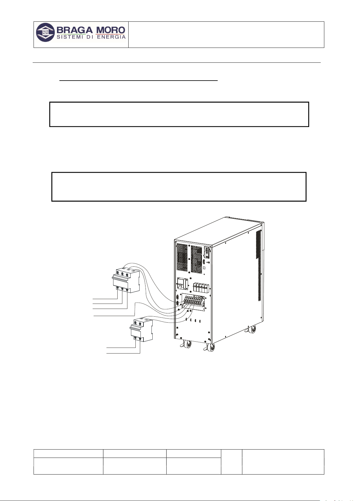
5.2.2.2 UPS input and output connection
Minimum 8AWG or 10 mm2 copper wires for input/output & battery cables are required for the ups.
Switch off all breakers before connecting cables.
Remove the cover of the terminals, see Fig 2-4, and connect the cables correspondingly
A B C Ni Lo No BAT
+
BATN BAT
-
INPUT A
INPUT B
INPUT C
INPUT N
OUTPUT L
BATTERY
"+"
BATTERY N
" "
BATTERY
"-"
OUPUT N
Fig. 5-4a 10k/15k/20k I/O terminals connection
A
B
C
L o
N o
Ni
B A T+B A TN BAT -
Positive(+) (8/9/ 10) Negative(-) (8/9/10)
UNI EN ISO 9001
-
2015 n° 9115.BRMO
UPS OCTANS 10/20kVA 3:1
USER MANUAL
File name Date Page
Code
PUV9E010/15/20-AK
DF19010A 10/04/2019 12 di 28
MD03006C All rights are reserved according to the law. Reproducing or distributing this document to third parties without permission is prohibited.
CAUTION!
Terminators are required so as to ensure the connections are firm
Don’t reverse the input L and N
Don’t connect the UPS input to a wall outlet or the outlet will get burnt.
Connect the UPS output L, N, E to L, N, E of load via a PDU. Tighten the screws and shelter the
terminals
CAUTION
!
Please connect the output Earth well before go for other operation
5.2.2.3 Connection of the UPS communication cables
1. USB cable provided in accessories can be used to connect the UPS with PC
2. Follow steps below to install SNMP (if purchased ):
a. Remove the cover of SNMP slot at UPS rear panel and keep it for further use.
b. Insert the SNMP card and tighten the screws
c. Connect the UPS with internet by network cable.
3. Refer to the SNMP manual provided to do SNMP setting.
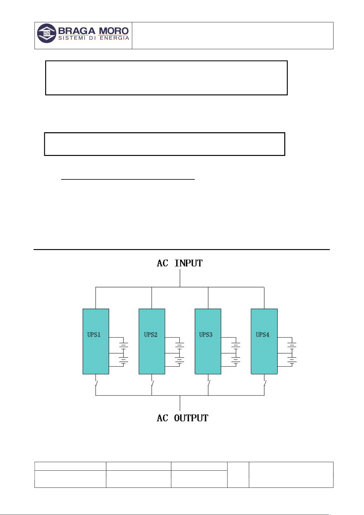
5.3 Connection of parallel system
Fig.5-5 parallel system
Make sure all the breakers are off and no output at the UPS output.

UNI EN ISO 9001
-
2015 n° 9115.BRMO
UPS OCTANS 10/20kVA 3:1
USER MANUAL
File name Date Page
Code
PUV9E010/15/20-AK
DF19010A 10/04/2019 13 di 28
MD03006C All rights are reserved according to the law. Reproducing or distributing this document to third parties without permission is prohibited.
CAUTION!
Connect the A/B/C/N/L and E well
Wire for requirement:
For 10KVA UPS, select 10AWG or 6mm² I/O copper line. The total line length is N*6mm².
For 15KVA UPS, select 8AWG or 10mm² I/O copper line. The total line length is N*10mm².
For 20KVA UPS, select 6AWG or 16mm² I/O copper line. The total line length is N*16mm².
(N equals the numbers of the UPS in parallel.)
6 Operation
6.1 Working modes
The UPS has AC mode, bypass mode, battery mode and ECO mode
6.1.1 AC mode
If the AC input and load capacity are in normal ranges, the load will be powered by inverter output, battery will
be charged at the same time. AC and inverter indicators on LCD control panel will be on (green).
CAUTION!
Please note below if the UPS input power is provided by a generator.
1) Don't switch on the loads before starting UPS. After the UPS has been started and
worked steadily, switch on the loads one by one. Suggest that the total capacity of the
loads should be lower than 30% of capacity of the generator.
2) It is suggested that the rating of generator should be 1.5-2 times of the capacity of
the UPS.
6.1.2 Bypass mode
When the AC power is connected and the UPS has not been switched on, or the UPS is overloaded after
switching on the UPS, it will go to bypass mode. The Loads will be powered by AC, battery will be charged,
and the bypass indicator on the LCD control panel will be on (yellow). But, if the bypass is beyond normal
range or absent, the UPS will not go to bypass mode and no power will be supplied to the loads.
6.1.3 Battery mode
In AC mode, if the AC is absent or beyond normal range, the rectifier and charger will stop working, the loads
will be powered by battery bank of which energy goes through inverter circuit. The Inverter’s and battery’s
indicators on LCD control panel will be on (green) and the alarm will beep every 2 seconds.
In battery mode, if the battery voltage becomes low and reaches the setting value, the system will give low
battery voltage alarm, beep once every second and the LCD will give low battery alarm, too.
CAUTION!
Charge batteries for at least 8 hours when the UPS is used at the first time, as battery
6.1.4 ECO mode
In AC mode, the UPS can be set to work in ECO mode if the load does require strict power purity and it can
be sustained in bypass mode normally. If the AC is beyond normal range, the UPS will transfer back to inverter
mode. The Efficiency for the UPS in ECO mode is much higher.

UNI EN ISO 9001
-
2015 n° 9115.BRMO
UPS OCTANS 10/20kVA 3:1
USER MANUAL
File name Date Page
Code
PUV9E010/15/20-AK
DF19010A 10/04/2019 14 di 28
MD03006C All rights are reserved according to the law. Reproducing or distributing this document to third parties without permission is prohibited.
6.2 Panel display, operation and running
The operation is simple, operators only need to read the manual and follow the operation instructions listed in
this manual, no need any special training.
6.2.1 Start up and turn off the UPS
Start up operation
1. Turn on the UPS in Line mode
Once AC Power Cord is plugged in, the UPS will start automatically and the LCD display of the UPS will be lit
on. You may view the data and set parameters on the LCD display as well as the LED display showing the
status of the UPS.
2. Turn on the UPS in Battery Mode
Press “On” on the front panel to start the UPS and in the meantime, the LCD display will light up. You may
view the data and set parameters on the LCD display and the LED display of the UPS will show the latest
status of the UPS.
Turn off operation
1. Turn off the UPS in line mode(without batteries)
① Press and hold the OFF key for 2 seconds to turn off the inverter and the UPS is in Bypass mode now;
on the contrary, you may press the hold the OFF key for 2 seconds in order to Change over back to inverter
mode.
② To shut down (turn off) the UPS completely, you need to turn off the input switch.
2. Turn off the UPS with connecting batteries
① Press and hold the OFF key for 2 seconds to turn off the UPS.
② After UPS is turned off, all LED and LCD will be extinguished and there is no output.
Remarks: When the UPS is turned off from the inverter mode, it will discharge DC Bus and then shut
down completely; therefore, sometimes, it takes more several seconds to complete.

UNI EN ISO 9001
-
2015 n° 9115.BRMO
UPS OCTANS 10/20kVA 3:1
USER MANUAL
File name Date Page
Code
PUV9E010/15/20-AK
DF19010A 10/04/2019 15 di 28
MD03006C All rights are reserved according to the law. Reproducing or distributing this document to third parties without permission is prohibited.
6.2.2 Faceplate display
Faceplate display illumination
ON
OFF
ESC
ENT
BYPASS
RECT INV OUTPUT
FAULT
Fig.6.2.2° Overview of the operating panel of the UPS
1. LCD Display Board
2. ESC
3. Off button
4. On button
5. right or down
6. Enter
7. Left or up
8. Output indicator
9. Inverter Indicator
10. Battery Indicator
11. Mains (AC) Indicator
12. Bypass Indicator
13. Fault Indicator
LCD display
1、LED indicator definition
1) Fault Indicator(red): “On ”indicates when a fault occurred; “Off” means no fault occurred.
2) Indicator(Green): “On” means AC is normal, “Off” means AC is not present, and blinking means
voltage is beyond normal range
3) Inverter Indicator(Green): “On” means when load is powered by inverter, “Off” means when it is
not working and blinking means it is in overload condition.
4) Bypass Indicator(Green): “On” means when UPS is in bypass mode, “Off” means not in bypass
mode and blinking means when the input is beyond normal range
5) Battery Indicator(Green):On: when UPS is in battery mode, Off: Not in Battery mode; Blinking:
when battery voltage is low or battery is not connected
6) Output Indicator(Green):On: when there is output, Off: no output.

UNI EN ISO 9001
-
2015 n° 9115.BRMO
UPS OCTANS 10/20kVA 3:1
USER MANUAL
File name Date Page
Code
PUV9E010/15/20-AK
DF19010A 10/04/2019 16 di 28
MD03006C All rights are reserved according to the law. Reproducing or distributing this document to third parties without permission is prohibited.
2、LCD display content
1) Running parameters
Input voltage/frequency, output voltage/frequency/current, temperature inside, UPS, battery
remaining capacity, battery charging/fully charged, battery voltage.
2) Alarm information (priority from high to low )
It provides shutting down, auxiliary power fault, output short circuit, inverter fault, rectifier fault, over
temperature, overload, charger fault, battery fault, battery capacity low, ready to shut down and
output fault.
3) Parameter setting
Menu setting, floating /boosting charging setting, battery capacity setting, ID of parallel UPS, output
voltage/frequency level/calibration.
1)Boosting charging voltage 2.30 to 2.35V per cell, floating charging voltage 2.20 to 2.29V per
cell
2)Battery capacity setting includes the Ah of each battery unit, battery quantity (8 to 10)*2,
parallel group number, low battery voltage alarm value (EOD ).
3)Parallel setting
4)UPS ID setting
4) Button Definition
Button Definition
ON Switch on the inverter by pressing and holding it for 1s when the
UPS is off
OFF
Switch off the inverter output by pressing and holding it for 1s
when the UPS is on, load will be powered by bypass output if the
bypass is normal
ENT Confirm the operation
ESC cancel and go to previous menu
◀ Turn to another menu or parameter
▶ Turn to another menu or parameter
5)UPS Messages reference table
Expla
nation
Content
Initialization CurState: Init
No export No-Out
At bypass Bypass
Rectifier working Mains
Battery mode Battery
Battery testing Testing
Starting Starting
ECO mode CurState: ECO
EPO mode CurState: EPO
UPS maintaining CurState: M-Byp
UPS fault CurState: Fault
Battery float charging Battery Charging
Battery Boost charging Battery Boost
Inverter on/off Invter ON/ Invter OFF
Master of UPS Inver Master
Maintenance switch close or open
SWMB ON/ SWMB OFF

UNI EN ISO 9001
-
2015 n° 9115.BRMO
UPS OCTANS 10/20kVA 3:1
USER MANUAL
File name Date Page
Code
PUV9E010/15/20-AK
DF19010A 10/04/2019 17 di 28
MD03006C All rights are reserved according to the law. Reproducing or distributing this document to third parties without permission is prohibited.
3 Display instruction
1) The main interface below comes out when the power is connected or the system is cold start. see Fig1
Fig.1:Main interface
2) Press ESC/ ◀ or ▶ button, it will change to the basic status interface, see Fig2 below
Fig.2:Basic status interface
3) Press the ENT button, it will change to main menu, see Fig3,
Fig.3: Main menu
4) An arrow icon will come out on the LCD when pressing the ENT, then the data info, status info, setting
info can be selected by pressing the right or left arrow button, and checking the details by pressing.
5) Select and confirm the data info to be viewed in detail. It contains the details of the AC input /output,
inverter, battery, BUS, parallel , temperature. See Fig 4 to 13 below.
Fig.4: Input volt info Fig.5:Input current info
10.0kVA
MODE: ONLINE
Volt: AN BN CN
Vin: 220 220 220
Vout:220V 50Hz
FIGUER
STATUS
SETTING
FIGURE
Mains-V
A:220.0 B:220.1
C: 220.0 50.0Hz
FIGURE
Output
220.0V 0.0A
50.0Hz Load: 0%
FIGURE
Output
0kW 0kVA
FIGURE
Mains-A
A:0.0 B: 0.0
C:0.0

UNI EN ISO 9001
-
2015 n° 9115.BRMO
UPS OCTANS 10/20kVA 3:1
USER MANUAL
File name Date Page
Code
PUV9E010/15/20-AK
DF19010A 10/04/2019 18 di 28
MD03006C All rights are reserved according to the law. Reproducing or distributing this document to third parties without permission is prohibited.
Fig.6:Output info Fig.7:Output info
Fig.8:Inverter info Fig.9:Battery info Fig.10 Battery info
Fig.11:Bus info Fig.12:Parallel info Fig.13:Temperature info
6) Select and confirm the status info can view the details, including status information, alarm information,
code, power rating and version. See Fig 14 to 15
Fig.14:main menu Fig.15:main menu
7) Select and confirm setting menu, setting information will be displayed on the screen, which includes
user set, system set, parallel set, battery sett, revise set. See Fig 16 to 24
Fig.16:setting menu Fig.17:setting menu
FIGURE
Invert
220.0V 50.0Hz
FIGURE
P Battery
0V 0.0A
0min 0%
FIGURE
N Battery
0V 0.0A
0min 0%
FIGURE
BUS
-370V +370V
CAP
:
0Hour
FIGURE
Parallel
ID: 1
P
_
Amount
:
0
FIGURE
Temperature℃
PFC:27 INV:27
ENV:27
STATUS
Code:11
Fault :0. 0.0.0
Model:10.0kVA
STATUS
Version
DSP
Ver:B006D001
LCD
SETTING
Mode: NOR
Batt num:16
B
att cap
:
7Ah
SETTING
V-Level:220V
F-Level:50Hz
SETTING
V-upper 15%
V-lower -45%
SETTING
Buzzer:Enable

UNI EN ISO 9001
-
2015 n° 9115.BRMO
UPS OCTANS 10/20kVA 3:1
USER MANUAL
File name Date Page
Code
PUV9E010/15/20-AK
DF19010A 10/04/2019 19 di 28
MD03006C All rights are reserved according to the law. Reproducing or distributing this document to third parties without permission is prohibited.
Fig.18:setting menu Fig.19:setting menu
Fig.20:Parallel setting
Fig.21:Batter self-Test Off Fig.22:Batter self-Test ON :to 10 seconds
Fig.23:Batter self-Test ON: to 10 minutes Fig.24:Batter self-Test ON: to EOD
SETTING
Parallel set
ID 1
P-amount 2
P-Redund 0
SETTING
BatTest: Off
SETTING
BatTest: |10s
SETTING
BatTest: |10m
SETTING
BatTest: |EOD

UNI EN ISO 9001
-
2015 n° 9115.BRMO
UPS OCTANS 10/20kVA 3:1
USER MANUAL
File name Date Page
Code
PUV9E010/15/20-AK
DF19010A 10/04/2019 20 di 28
MD03006C All rights are reserved according to the law. Reproducing or distributing this document to third parties without permission is prohibited.
6.3 Working Mode and transferring
Usually, the UPS should be set to work in AC mode, so it will transfer to battery mode automatically without
interruption when AC fails. When the UPS is overloaded, it will transfer to bypass mode without interruption.
When the inverter is defective or over temperature occurred inside the UPS, the UPS will transfer to bypass
mode if the bypass is normal.
6.3.1 Transfer to bypass if overload
When the load of UPS is beyond normal range and lasts for the time set, it will transfer to bypass mode and
beeps twice every second, then the load is powered by AC directly. Please decrease the load immediately
until the alarm is eliminated. The UPS will start the inverter after 5 minutes. In order to protect the load and the
UPS, it is required to set the limitation times of transferring to bypass mode due to overload in 1 hour. If it
exceeds the limitation times set, the UPS will keep in bypass mode.
6.3.2 Normal mode to battery mode
The UPS will go to battery mode if the AC is failed. The UPS will shut down automatically if batteries are
drained. When AC recovers, the UPS will start the inverter automatically.
6.3.3 Go to bypass mode due to over temperature
The temperature inside UPS may be high if ambient temperature is high or the ventilation is poor, then the
UPS will go to Bypass mode, fault indicator will be on (red), the LCD will display that the inner temperature is
high, long beeps will come. If so, please cut off the input power of the UPS, move objects that affecting the
ventilation far from the UPS if any or increase the distance between the UPS and the wall. Wait until the UPS
temperature becomes normal then restart it.
6.3.4 Output short circuit
When the UPS output is in short circuit, the UPS will cut off the output, fault indictor will be on (red ), the LCD
will display output is in short circuit, long beeps come. If so, please disconnect the load in short circuit, cut off
the UPS input power and wait for 10mins, the UPS will shut down automatically or press the off button to shut
down in after10s. Before restarting the UPS, please make sure that the short circuit problem has been solved.
6.3.5 Batter self-Test
The page is the introduction to the Battery self-test setting. The default Settings is “OFF” when the UPS has
no need of the battery self-test function. When turn to “ON”, batteries can do the self-test automatically per 30
days. Three kinds of Battery Self-test Time can be choosing as below.
When choosing 10s, UPS can transfer to Battery Mode automatically per 30 days. And the Battery Self-test
Time is 10 seconds.
When choosing 10m, UPS can transfer to Battery Mode automatically per 30 days. And the Battery Self-test
Time is 10 minutes.
When choosing EOD UPS can transfer to Battery Mode automatically per 30 days.
And the Battery Self-test Time is EOD.
6.4 UPS monitoring
Please refer to the instruction of the UPS monitoring software provided.
6.5 Display Messages/ Records
This section lists the event and alarm messages that the UPS might display. The messages are listed in
alphabetical order. This section is listed with each alarm message to help you troubleshoot problems
.
This manual suits for next models
2
Table of contents
Other Braga Moro UPS manuals

Popular UPS manuals by other brands


GE
GE Digital Energy LP 11 operating manual

Toshiba
Toshiba UNINTERRUPTIBLE POWER SYSTEM 1600XP Installation and operation manual

PS Audio
PS Audio PerfectWave Power Plant 10 Owner's reference

ABB
ABB PowerValue 11 T Series user manual

Emerson
Emerson Liebert GXT4-5000RT230 user manual

Eaton
Eaton 9E 10000i manual