Braun Group G10K User manual

Braun Group ONLINE UPS
G10KVA�G30KVA 3
:
3
User Manual

Table of Contents

1 Safety Information
CAUTION
WARNING
I
Safety and General Information

Note: Symbol instructions
Symbol Significations Symbol Significations
@
£ X
ON
OFF
0
-
---
~2~

2.1 Specifications
MODEL
G
10
K
G
15
K
G
20
K
G
30
K
INPUT
I
OUTPUT
I I I
I
BATTERY

SYSTEM
I
OTHERS
°
350 X 785 X
472 X 910 X

2.2 Front panel features
Front panel of long
time model UPS
Front panel of 10 kVA
standard model UPS
(1 floor batteries)
2.3 Rear panel features
Rear panel of 1 O kVA
long time model UPS
Rear panel of 10 k
standard model UPS
(1 floor batteries)
~5~
Front panel of standard
model UPS
(3 floors batteries)
Rear panel of 10 kVA
standard model UPS
(3 floors batteries)

1 \
2,
3,
4,
5,
6,
7,
8,
�-I
�
8 ■
Rear panel of 15 k / 20 k /
30 k long time model UPS
Rear panel of 15 k / 20 k /
30 k standard model UPS
Main input terminal 9, RS232 port
Battery input terminal 10, USB port
Bypass input terminal 11 , EPO
Output terminal 12, Battery temperature compensation sensor (optional)
Main input breaker
13,
Intelligent slot 1 (SNMP / AS400 / RS485 optional)
Bypass input breaker 14, Intelligent slot 2 (SNMP / AS400 / RS485 optional)
Maintenance switch
15,
Parallel port ( optional)
Fan 16, Inbuilt battery breaker
~6~

3 Installation
3.1 Unpacking inspection
Note:
3.2 Single System Installation
& CAUTION
~7~

3.2.1 Installation environment and location
3.2.2 Wiring
~8~

B . ER1
�--atte+
3.2.3 Connect external battery (Long time model UPS)
~9~

To Battery input terminal of UPS
Positive Negative
battery breaker
16/18/20
3.3 Parallel System installation
3.3.1 Parallel installation requirements

3.3.2 Parallel installation procedure
=1
=

Note:

Mains input
Public input terminal
Public output terminal block
Load Load Load Load - - -
+-

3.3.3 Parallel UPS operation
►Start up parallel UPS
Startup by mains power
Power ON
Startup by the battery
Power ON
Power ON
Shut down parallel UPS
Power OFF
Power OFF
►Parallel UPS system maintenance

4 Operation Instructions
4.1 Display panel
4.1.1 Buttons
Power ON ■
Power ON
Power OFF
Power OFF
Self Test/ Mute
I
Menu settings ■
■

Page turning /Inquiry
4.1.2 LED indicators
Icons
Function Description
Inverter indicator
(Green)
Battery indicator
(llow)
Bypass indicator
(llow)
Alarm indicator
(Red)

4.1.3 LCD display
vDCAM 8 PCS
0
f •
Operation mode and icons display area:

Value display and menu settings area:
Date and ult alarm display area:
4.1.4 Equivalent UPS working status to the indicator
Buzzer sound Description
The panel indicator display
No. Working status Audible alarm
Normal Battery Bypass Fault
1 Utility mode/ Frequency conversion mode
•
• *
2 Battery mode
This manual suits for next models
3
Table of contents
Popular UPS manuals by other brands
Tescom
Tescom XA-200P Series user manual

Huawei
Huawei UPS5000-S-1600 kVA user manual

TCW Technologies
TCW Technologies Integrated Back-up Battery System manual

Fideltronik Inigo
Fideltronik Inigo KR 1000 RTC user manual
Sola Hevi Duty
Sola Hevi Duty S4K5U6000-5 user manual
Metek
Metek Powervar Security II Series manual

CertaUPS
CertaUPS C400-010-B Installation and owner's manual
Eaton
Eaton 5000 VA user manual

Avaya
Avaya 1 Series Site Preparation, Installation And Operator's Manual
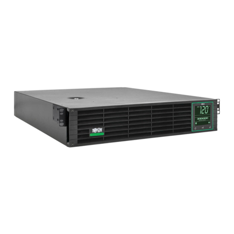
Tripp Lite
Tripp Lite SMART3000RM2UL owner's manual

Njoy
Njoy Septu Series user manual

MGE UPS Systems
MGE UPS Systems Pulsar MX Frame 15000 RT Installation and user manual
