Brahler CDSVAN User manual

Operating instructions
Rev 3.80
CDSVAN Digital Conference Management System
B8 –AD/DA Interface

B8 CDSVAN
2 Copyright by Brähler ICS
Printed in Germany
Should you have questions about this manual please contact:
Brähler ICS Konferenztechnik
International Congress Service AG
Auf der Alten Burg 6
53639 Königswinter, Germany
T +49 (0)2244 930-0
You will find further information about our Products on the internet at:
www.braehler.com
© 2012 BRÄHLER ICS AG, Königswinter
All rights reserved, especially (also partly) the translation, reprint, reproduction through copying or other
similar methods.
All other trademarks and trade names are the property of their respective owners.
BRÄHLER ICS reserves the right to make changes without notice.
Operating instructions B8 BGE-B8 (3.x).DOC

CDSVAN B8
Copyright by Brähler ICS 3
Safety instruction
! CAUTION !
DANGER OF ELECTRIC SHOCK
DO NOT OPEN DEVICES
Do not open housing with mains cable connected.
Maintenance operations may only be done by
qualified personnel.
Our equipment and installations have been built and tested according to the latest state of the art. Under
normal conditions, they do not require any special maintenance.
However, please be aware of the following:
secure and stable position of the installation
sufficient ventilation - never operate equipment near heat sources such as heating radiators etc.
power connection - install all power cables to avoid damaging
connecting cables - avoid trip-traps
liquids - avoid penetration of liquids into the housing
exclusively operate equipment via wall sockets that are connected to ground according to the
relevant specifications and regulations
Warning: Never expose equipment to rain or humidity.
Please be also aware of the fact that rough handling of the equipment, such as strong bumps or vibrations,
may result in damages. Inappropriate handling and storage, i.e. handling and storage not in conformity with
the operating instructions, may as well lead to equipment damages.

B8 CDSVAN
4Copyright by Brähler ICS

CDSVAN B8
Copyright by Brähler ICS 5
Content
Safety instruction.............................................................................................. 3
About this manual ............................................................................................. 6
Symbols ................................................................................................................ 6
Important remarks................................................................................................... 7
For customers in the EU and in the USA ..................................................................... 7
For customers in the United Kingdom......................................................................... 7
General ................................................................................................................. 8
The B8 AD/DA Interface .................................................................................... 9
Included in delivery ............................................................................................... 10
Accessories ......................................................................................................... 10
System Components ............................................................................................. 10
CAT5 Cable usage ................................................................................................ 10
Operating Controls .......................................................................................... 11
Front view ........................................................................................................... 11
Rear view ............................................................................................................ 11
DIP Switch Settings .............................................................................................. 13
Device ID ....................................................................................................................... 13
WordClock Mode............................................................................................................. 14
Slave Sync ..................................................................................................................... 14
Master Clock .................................................................................................................. 14
AF Control...................................................................................................................... 14
Cable Length .................................................................................................................. 14
Termination .................................................................................................................... 15
Ground-to-Earth .............................................................................................................. 15
Analogue Audio Connections .................................................................................. 16
Digital Audio Connections ...................................................................................... 16
Audio Control....................................................................................................... 17
Automatic Memory ............................................................................................... 17
Audio Routing ...................................................................................................... 18
MotorMixer connection .......................................................................................... 19
16/32 Channel Audio Distribution ..................................................................... 20
Appendix ....................................................................................................... 22
Technical Data ..................................................................................................... 22
Troubleshooting table ............................................................................................ 23
SERVICE FORM .................................................................................................... 25
Block diagrams ..................................................................................................... 27
Your current DIP switch settings: ............................................................................ 29
Contact information .............................................................................................. 31

B8 CDSVAN
6Copyright by Brähler ICS
About this manual
Symbols
The meanings of the symbols and fonts used in this manual are as follows:
Indicates an important note, if not minded, the functionality of the unit, the security of your data, or
your health are put at risk.
Supplementary information, remarks, and tips follow this symbol.
Text which follows this symbol describes activities that must be performed in the order shown.
Texts in bolded letters require your special attention.

CDSVAN B8
Copyright by Brähler ICS 7
Important remarks
For customers in the EU and in the USA
The equipment has been tested and found to comply with the limits of the CE test. These limits are designed
to provide reasonable protection against harmful interference when the equipment is operated in a
commercial environment. The equipment generates, uses, and can radiate radio frequency energy and if not
installed and used in accordance with the user manual it may cause harmful interference to radio
communications. You are cautioned that any changes or modifications not expressly approved in this manual
could void your authority to operate this equipment.
For customers in the United Kingdom
The wires in the main lead are coloured in accordance with the following codes:
Green-and-yellow: Earth
Blue: Neutral
Brown Live
The colours of the wires in the mains lead of this apparatus may not correspond with the coloured markings
identifying the terminals in your plug, so please proceed as follows:
The green-and-yellow wire must be connected to the terminal in the plug marked with the letter E or with the
safety earth symbol or marked with green-and-yellow colour. The blue wire must be connected to the
terminal marked with the letter N or marked with black colour. The brown wire must be connected to the
terminal marked with the letter L or marked with red colour.
The equipment must be connected to earth!
Safety
Check that the operating voltage of the unit is identical with the voltage of your local power supply. If a
voltage conversion is required, consult your BRÄHLER ICS dealer or qualified personnel.
Should any liquid or solid object fall into the cabinet, unplug the unit and have it checked by qualified
personnel before operating it further. Unplug the unit from the wall outlet or set the Main Power switch to
OFF if it´s not used for several days. To disconnect the cord, pull it out holding the plug. Never pull the cord
itself.
Installation
Allow adequate air circulation to prevent internal heat built-up. Do not place the unit on a surface (rugs,
blankets, etc.) that may block the ventilation holes.
Do not install the unit in a location near heat sources such as radiators or air ducts, or in a place exposed to
direct sunlight, excessive dust or humidity, mechanical vibration or shock.
To avoid moisture condensations do not install the unit where the temperature may rise rapidly.
Cleaning
To keep the cabinet in its original condition, periodically clean it with a soft cloth. Stubborn stains may be
removed with a cloth lightly dampened with a mild detergent solution. Never use organic solvents such as
thinners or abrasive cleaners since these will damage the cabinet.
Repacking
Save the original shipping carton and packing material; they will become handy if you ever have to ship the
unit.
For maximum protection, re-pack the unit as originally packed from the factory.
If not supplied with the equipment, a complete transportation and storage box system is available from
BRÄHLERICS. We recommend you to use this system for long-term protection and care.

B8 CDSVAN
8Copyright by Brähler ICS
General
Please keep this manual together with the B8. If you pass on the units to other parties, please include this
manual.
Please read the manual carefully, taking special care when you see this symbol as
indicates important information!
This product conforms to the rules of the following European regulations:
2004/108/EG
Council directive to the alignment of the rules, of rights of all member states about the electromagnetic
compatibility, adapted through RL 91/263/EWG, 92/31/EWG and 93/68/EWG of the council. Further
information is available on request.
The warranty invalidates, if you cause (generate, precipitate) inappropriate use or handling of the
unit.

CDSVAN B8
Copyright by Brähler ICS 9
The B8 AD/DA Interface
Thank you for choosing the B8 AD/DA interface.
The B8 is your interface to the digital world and of course, vice versa.
The B8 AD/DA interface offers you a high quality audio conversion from analogue to digital (AD) and digital
to analogue (DA) in one single 2HU housing.
Almost all digital sound processing systems offer a large amount of digital channels, but due to space
restrictions the AD/DA conversion has to be outsourced, if more channels are required.
At this point the B8 starts its work.
Feed in the analogue signals, using the analogue input sockets at the rear side of the B8. Depending on the
available patch cable, either XLR or ¼ inch jacks can be used.
All inputs are electrically balanced to avoid electromagnetic interference (transformer balanced version
available on request).
The B8 operates line and microphone level signals. The 8 inputs are individually adjustable to the level of
the incoming signal. Even phantom power is provided by the B8 and switch able to all microphone inputs.
High quality microphones (e.g. condenser microphones) can be connected directly to the B8 without any
additional power supply.
All input channels are equipped with individual level adjustment of +/- 9dB.
To deliver you the best audio performance the analogue-to-digital conversion works with a 24 Bit resolution
and selectable sample rates of 32, 44.1 or 48 kHz.
The B8 offers the common digital multichannel interfaces ADAT®and of course an interface to the CDSVAN
system –EDAT.
With the EDAT (RJ45) connectors the number of in- and outputs can be extended to 16, linking a second B8
to the first one.
The B8 can also be used as a digital 32 channel (16 channels in and 16 channels out) audio distributor with
the specifications shown above independently of the CDSVAN system.

B8 CDSVAN
10 Copyright by Brähler ICS
Included in delivery
Mains power cable - 2 metres, black
Accessories
19” rack mounting set - silver anodised (no. 60.KIT.2)
Terminator - TERM216 (no. 06.6161)
Data cable - CAT5 several cable lengths available *) see below
Adapter CCAT5 - crossed cable adapter to connect two B8 IN/OUT (PC) sockets
System Components
CDSVAN pro Audio processing software
DSP6/15 RJ45 DSP Card with 6 or 15 digital sound processors and EDAT I/O plate
DOLV Interpreter Console for 32 channels
DV9 Delegates Unit
PV9 Chairman Unit
EDV9 Delegate Unit, build-in version
EPV9 Chairman Unit, build-in version
PSU04 Power Supply Unit, up to 4 branches for interpreter consoles/ delegate units
PSU01MA/SL Additional Power Supply for interpreter consoles/ delegate units
B8 AD/DA Interface 8 channels
MotorMixer Remote Mixer with 8 motorised faders
MSI8V INFRACOM®Infrared Transmitter
IRad INFRACOM ® Infrared Radiator
IRX INFRACOM ® Infrared Receiver
Cables CAT5 *) see below
CAT5 Cable usage
*) The system warranty is only valid with the intended use of the CDSVAN system cables specified
below. The usage of any other cable type will void the warranty.
Specified patch cable: Brähler CAT5 System Cable (Art.-No. 13.5331)
Specified installation cable: Brähler CAT5 Installation Cable (Art.-No. 13.5330.H)

CDSVAN B8
Copyright by Brähler ICS 11
Operating Controls
Front view
The front side of the B8 is equipped with 3 LED’s per channel to indicate the following items:
- MIC or LINE level selected (MIC if red)
- AF –(Green LED) audio signal available at analogue input
- PEAK (Red LED) indication for maximum audio level
If your input audio signal often forces the red peak LED to illuminate, please reduce the sensitivity
either of the input (see below) or the output of the connected device. Otherwise you risk to overdrive
the AD converters.
- Phantom power for all microphone level inputs.
- A Power switch with “power-ON” LED is dedicated on the right hand side of the front panel.
Rear view
The rear side is equipped with:
- 8 analogue inputs XLR/ ¼”
- 8 analogue outputs XLR
- Main power connector
- Ground connector
- 2 EDAT (RJ45) sockets for VAN I/O and LINK
- 3 ADAT®sockets for ADAT IN, OUT and TRU
- Wordclock connector (BNC)
- MIDI IN and OUT
- 12 DIP switches for B8 set-up

B8 CDSVAN
12 Copyright by Brähler ICS
All components are described on the following pages.
CDSVAN B8
Copyright by Brähler ICS 13
DIP Switch Settings
Some basic settings have to be done at the rear side of each B8 unit within the system. Besides the cabling
of each audio patch cable to the desired in- and outputs, you can choose some working modes the B8 offers
to match the system requirements:
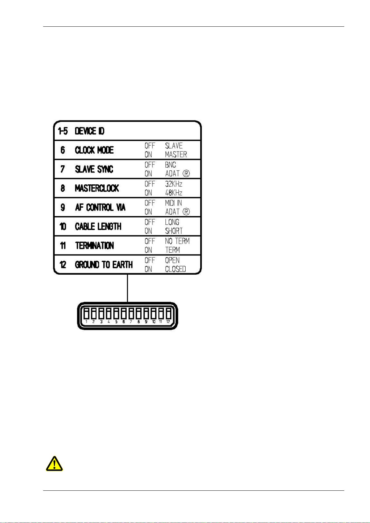
Each DIP switch has two positions:
OFF - switched to the upper position
ON –switched to the lower position
DIP Switches:
Device ID
(Word) Clock mode
Slave sync(hronisation)
Masterclock
AF control via
Cable Length
Termination
Ground to Earth
Device ID
Switches 1 –5.
The B8 needs to have a unique ID number to be identified by the CDSVAN system.
This ID is used by the B8 Control Module to identify the corresponding B8. Double numbers force the units to
behave the same, when connected to the control device (see below).
The ID can range between 0 and 31.
Please make the corresponding settings to the first 5 switches in binary format.
Example: B8 No. 0 - switches 1 –5 OFF
B8 No. 1 - switches 1 ON and 2 –5 OFF
B8 No. 2 - switches 1 OFF and 2 ON and 3 –5 OFF
B8 No. 3 - switches 1 and 2 ON and 3 –5 OFF
B8 No. 4 - switches 1 and 2 OFF and 3 ON and 4 –5 OFF …
B8 No. 31 - switches 1 –5 ON
If no B8 control is connected, it will work with its default settings: Line level on all channels.
The ID’s are independent of the positioning in the system of the B8 units.

B8 CDSVAN
14 Copyright by Brähler ICS
WordClock Mode
Switch 6
Only ONE wordclock Master is allowed in a digital audio environment. Each digital device's internal clock
operates with a slightly different sample frequency from the other. Even if all connected devices are set to
the same sample rate. Audible pops and clicks may occur when unsynchronised digital sources are mixed.
The wordclock can be generated by the B8 or delivered by the DSPx card or an external wordclock
generator.
We recommend to use the B8 as wordclock slave, when connected to a digital system (e.g. CDSVAN).
The B8 will get all necessary sync information from the DSPx card.
Turn the DIP switch to OFF to make the B8 wordclock slave.
In this case switch no. 8 is not activated, please select the master source with switch 7.
Turn the DIP switch to ON to make the B8 wordclock master.
In this case switch no. 7(Slave Sync) is not activated. Please select the desired sample rate with switch 8.
Slave Sync
Switch 7
With this switch the synchronisation source has to be defined (Only if switch 6 is OFF).
Choose between BNC for an external clock generator or ADAT®for digital systems connected via ADAT®
or EDAT (e.g. CDSVAN).
To connect the B8 to an external wordclock generator use the BNC socket “WORDCLOCK”.
Master Clock
Switch 8
With this switch the sample rate has to be defined (only if switch 6 is ON).
Choose OFF for 32 kHz.
Choose ON for 48 kHz.
AF Control
Switch 9
The B8 can be controlled from a remote device. If you don’t want to use the B8 control module within
CDSVAN, you can connect any standard MIDI device to the MIDI in- and output to control the input
channels.
Choose OFF for MIDI
Choose ON for ADAT®or EDAT (RJ45 @ DSPx card)
Cable Length
Switch 10
The digital audio driver of the converter should be adjusted to the cable length connected to the “PC” socket.
Choose OFF for LONG for cables between 20 and 100 metres
Choose ON for SHORT for cables between 1 and 30 metres.

CDSVAN B8
Copyright by Brähler ICS 15
Termination
Switch 11
Electrical digital data lines have to be terminated, to avoid data transmission errors.
So please take a closer look to the instructions below, if you use the B8 in combination with a DSPx RJ45
card.
Using one B8 for 8 channel AD/DA conversion via EDAT on one DSPx RJ45 socket:
The terminator switch must be set on ON, to terminate the connected line (8 in and 8 out on one CAT5
cable).
Using two B8 for 16 channel AD/DA conversion via EDAT on one DSPx RJ45 socket:
The internal terminator (DIP 11) on the first B8 (connected directly to the DSPx card) has to set to OFF.
The whole digital audio line will be terminated at the LINK socket of the second B8 with the terminator plug
(Term VAN16 - grey cap 06.6133)
Ground-to-Earth
Switch 12
DIP switch 12 disconnects B8's internal ground from housing:
To avoid any power stroke metal housing of the B8 must be connected to earth.
For most applications best audio quality is expected, if ground is internally connected to earth as well.
However, more than one earth connection in the audio system may cause hum or noise.
If there is any hum or distortion, disconnecting of B8's electronic circuitry from earth may deliver the solution.
Choose OFF for open - B8's ground is floating
Choose ON for closed - B8's ground is connected to earth (default)
For low impedance grounding B8's housing can be connected via extra ground at the rear side.
Ground connector and main power socket

B8 CDSVAN
16 Copyright by Brähler ICS
Analogue Audio Connections
Analogue In- and Outputs:
OUT: 8 times XLR output, balanced.
IN: 8 times XLR or ¼” input for either line or microphone level.
Digital Audio Connections
The B8 is equipped with ADAT®interface:
ADAT®
IN: 8 channel digital in
OUT: 8 channel digital out
THRU: all 8 channels fed into ADAT®IN can be looped to another
destination
The B8 is equipped with EDAT (RJ45) interface:
PC: VAN I/O direct connection (IN and OUT) to the DSPx RJ45 card
(channel 1-16 / 1-8 at the first B8)
LINK: connection of channel 9-16 to/ from a second B8
Concerning the used CAT5 cables see page 10
The B8 is equipped with MIDI interface:
MIDI IN: connection from MIDI out of the connected MIDI device
MIDI OUT: connection from MIDI in of the connected MIDI device

CDSVAN B8
Copyright by Brähler ICS 17
Audio Control
Knowledge of CDSVAN system required (please refer to the CDSVAN manuals).
All audio settings concerning the sensitivity of the analogue inputs of the B8 are done via the CDSVAN
software:
(Please refer to the DIP switches 1-5 and 7)
Using the B8 Control, all inputs at the B8 can be individually switched to microphone or line level.
For a smooth adjustment to the signal source, the B8 Control is equipped with a rotary knob for each
channel to in- or decrease the input level with +/- 9 dB.
Type in the ID number of the B8 unit you want to control. All settings will be stored automatically.
Different Set-ups for the connected B8s can be stored within the project file.
The B8 also provides phantom power to all microphone inputs.
Phantom power button (48V)
Automatic Memory
The B8 is equipped with a flash memory to store the current settings of the audio inputs (line, mic, phantom
power).
These settings will automatically be recalled, when the B8 is switched on.
The memory is automatically updated, whenever the input channels are readjusted using the B8 control or
an external MIDI device.

B8 CDSVAN
18 Copyright by Brähler ICS
Audio Routing
Up to eight B8 can be connected to one DSPxRJ45 card, to provide up to 64 analogues in- and outputs
(please refer to bloc diagram on page 24).
In combination with three DSP6EDAT cards and 24 B8 converters CDSVAN delivers a digital mixing, routing
and effect device for up to 192 channels in studio audio quality.
One B8 control module can operate several B8, or drag a separate B8 control module for each connected B8
into your project window.
The MIDI (red cabling) output of each B8 control module has to be connected to the MIDI input of the EDAT
Dest(ination) pad.
The audio connections (blue cables) are corresponding to the analogue output of the B8.
Example: DSP6 EDAT C Dest In 1 is connected to the first output of the 1st B8.
DSP6 EDAT C Dest In 2 is connected to the second output of the 1st B8.
DSP6 EDAT D Dest In 1 is connected to the first output of the 2nd B8 (connected via LINK).
DSP6 EDAT D Dest In 2 is connected to the second output of the 2nd B8.
The last two channels (DSP6 EDAT D Dest In 1, DSP6 EDAT D Dest In 2)
can be defined as channel 9 and 10 and so on.
The EDAT X Source pads can be used in the same way, but without any B8 control MIDI wiring.

CDSVAN B8
Copyright by Brähler ICS 19
MotorMixer connection
Hardware connection
It’s also possible to connect a remote mixing console to the
MIDI interface, such as the MotorMixer in CDSVAN.
No additional cabling (of course the CAT5) is necessary.
Please make the corresponding wiring in the CDSVAN
software with the corresponding software mixing consoles.
Please connect the “MIDI IN” form the MotorMixer to the
“MIDI OUT” of the B8 and vice versa.
Software connection
SW cabling MOTORMixer:
The MotorMixInterface is
connected (red cables) to the
MIDI source (MIDI OUT @ the
B8) and the MIDI destination
(MIDI IN @ the B8).
SW cabling MotorMixer & B8 control:
If you want to use the
MotorMixer in combination
with the B8 control, the two
different MIDI signals need to
be merged for the
transmission on the CAT5
data cable to the B8. The
MIDI merger is located under
the folder “Special devices”.
MIDI Mixer
MIDI OUTMIDI IN
MIDI IN
MIDI OUT

B8 CDSVAN
20 Copyright by Brähler ICS
16/32 Channel Audio Distribution
The B8 (AD/DA converter) is also designed for digital multichannel audio transmission in full duplex without
any additional computer hardware (stand-alone).
This option allows to transport audio signals e.g. from the stage to your control room and vice versa in
CDSVAN (studio) quality. Up to 32 channels can be transmitted with one single CAT5 cable.
16 channel audio distribution
The following diagram gives an overview of the audio flow for 16 channels:
This example shows you the transmission of 16 channels (8 to and 8 from).
Audio signals fed in at the B8 A1 can be taken out at the second B8 B1.
Example: B8 A1 input channel 1 is available at B8 B1 output channel 1 (green cables)
B8 B1 input channel 1 is available at B8 A1 output channel 1 (blue cables)
…
Only one wordclock master is allowed, so please set the corresponding DIP switches accordingly.
DIP switch setting to the example above concerning the wordclock and sample rates:
DIP Switch B8 A1 B8 B1
6 ON OFF Clock mode
7 ON ON Slave sync source
8 ON/OFF ON/OFF Sample rate setting
DIP switch 8: the Master generates the wordclock, which can be 32 or 48 kHz. The slave gets the wordclock
via the CAT5 connection, so the DIP switch setting there (B8 B1) is not important.
An external wordclock generator can also be integrated using the BNC connector. In this operation the DIP
switch setting is like this:
DIP Switch B8 A1 B8 B1
6 OFF OFF Clock mode
7 OFF OFF Slave sync source
Table of contents
Other Brahler Conference System manuals


