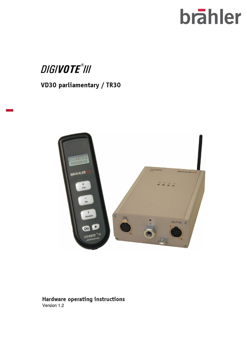
Brahler DIGIMIC User manual

DIGIMIC®
Digital Discussion System - wireless
Operating instructions
Release 1.2

2
Printed in Germany
Should you have questions about this manual please contact:
Brähler ICS Konferenztechnik
International Congress Service AG
P.O. Box 3264
53627 Königswinter, Germany
T (0)2244 930-0
F (0)2244 930-450
www.braehler.com
© 2009 BRÄHLER ICS AG, Königswinter, Germany
All rights reserved, especially (also partly) the translation, reprint, reproduction through copying or other
similar methods.
BRÄHLER ICS reserves the right to make changes without notice.
Oct-09

3
Table of contents
About this manual.............................................................................................4
Symbols...................................................................................................................4
General information...................................................................................................4
Important information ........................................................................................ 5
Important safety instructions ......................................................................................5
Important safety information.......................................................................................6
DIGIMIC®Digital Conference System.................................................................... 8
Wireless system components......................................................................................8
Wired system components .........................................................................................8
CE Conformity and FCC Statement..............................................................................9
Autonomous mode.......................................................................................... 10
DSpark Radio Transceiver Unit............................................................................................11
Connecting the Power Supply .......................................................................................... 12
Transmitting antenna .........................................................................................................13
Adjustment of the transmitting antenna ............................................................................13
Settings ...........................................................................................................................14
REGISTER......................................................................................................................15
HIGH POWER.................................................................................................................15
PRIOrity mode................................................................................................................15
LS INTERN.....................................................................................................................16
DDoc Docking Unit............................................................................................................17
Slave mode .................................................................................................... 19
Single operation mode ..................................................................................... 21
System startup .................................................................................................................21
DDoc Docking Unit............................................................................................................21
Indication of battery status..............................................................................................21
Automatic switch off......................................................................................................22
Charging of the battery pack...............................................................................................23
Charging via power supply...............................................................................................23
Charging via DTray Charging Tray ....................................................................................23
Removing the battery pack ..............................................................................................23
DTray Charging and Transport Tray ..................................................................................... 25
Multi room operation ....................................................................................... 26
Multi room operation mode examples...................................................................................26
Radio system number.........................................................................................................27
Adjusting DMic/DDoc combination to a room (0 – 4) .............................................................28
Resetting of DDoc Docking Units.........................................................................................28
Allocation of DDoc Docking Units........................................................................................28
Technical data ................................................................................................ 29
DSpark Radio Transceiver Unit............................................................................................29
DDoc Docking Unit............................................................................................................30
Appendix ....................................................................................................... 31
Block diagrams .......................................................................................................31
SERVICE FORM ......................................................................................................35
Contact information.................................................................................................37

About this manual
4
About this manual
Please keep this manual together with the system units. If you pass on the units to other parties, please
include this manual.
Symbols
The meanings of the symbols and fonts used in this manual are as follows:
Indicates an important note, if not minded, the functionality of the unit, the security of your data, or
your health are put at risk.
Supplementary information, remarks, and tips follow this symbol.
Text which follows this symbol describes activities that must be performed in the order shown.
Texts in bolded letters require your special attention.
General information
Please read the manual carefully, taking special care when you see this symbol as indicates
important information!
All brand names (marked with *) are registered trademarks of their respective owners.
The warranty invalidates, if you cause (generate, precipitate) inappropriate use or handling of the
unit.

Important safety instructions
5
Important information
Important safety instructions
•Read these instructions for use.
•Keep these instructions in a safe place.
•Heed all warnings.
•Follow all instructions.
•Do not use near water.
•Clean only with a dry cloth.
•Do not block any ventilation openings. Install in accordance with the manufacturer’s instructions.
•Do not install near any heat sources such as central heating radiators, electric heaters, stoves, or
other units that produce heat (e.g. amplifiers).
•This unit is supplied with an IEC mains cable complete with a molded mains plug. This is for your
safety – do not tamper with the mains. If the supplied cable does not fit your mains socket, please
consult a competent electrician for a replacement cable that matches the power output sockets in
your country, or to replace the obsolete socket with one to current standards.
•Protect the mains cable from being walked on or pinched, particularly at plugs, convenience
receptacles, and the point where it exits from the unit.
•Only use attachments/accessories specified by the manufacturer.
•Use only with the cart, stand, tripod, bracket, or table specified by the manufacturer, or sold with the
unit. When a cart is used, use caution when moving the cart/unit combination to avoid injury from tip-
over.
•Unplug during lightning storms or when unused for long periods of time.
•Refer all servicing to qualified service personnel. Servicing is required if the unit has been damaged
in any way, such as mains cable or plug damage, liquid has been spilled, objects have fallen inside,
the unit has been exposed to rain or moisture, does not operate properly or has been dropped.

Important safety information
6
Important safety information
Warning!
To reduce the risk of fire or electric shock, do not expose the unit to rain or moisture. Do not open
the unit as there are potentially dangerous voltages present inside. Refer all servicing to qualified
service personnel.
Caution! Use only accessories recommended by the manufacturer to avoid fire, electric shock, or other
hazards. To prevent the risk of electric shock, do not remove cover or back. No user serviceable
parts inside! Refer all servicing to qualified service personnel.
Warning! Power source
The central control unit is a Class 1 unit. It must only be connected to properly grounded power
outlets. This unit should be operated only from the type of power source indicated on the marking
label.
lf you are not sure of the type of power supply to your building, consult your dealer or local power company.
Disconnection from the mains
To disconnect the unit from the mains, pull the mains plug out of the wall outlet.
Overload
Do not overload wall outlets and extension cables as this may result in fire and electric shock.
Objects and liquids
Never push objects of any kind through openings of this unit as they may touch dangerous voltage points or
short-out parts that could result in fire or electric shock. Never spill liquids of any kind onto the unit. Should a
spillage occur, unplug the unit and have it checked by a technician.
Maintenance and care
No user serviceable parts inside! Do not attempt to service this unit yourself as opening or removing covers
may expose dangerous voltage or other hazards. Refer all servicing to qualified service personnel.
Clean only with a dry cloth. Do not use detergents or other liquids.
Replacement parts
When replacement parts are required, be sure the service technician uses replacement parts specified by
the manufacturer or those that have the same characteristics as the original part.
Unauthorized substitutions may result in fire, electric shock, or other hazards.
Safety check
Upon completion of any service or repairs to this unit, ask the service technician to perform safety checks to
determine that the product is in proper operating condition.

Important safety information
7
The DIGIMIC conference system is state of the art and has been designed to meet the regulations in force.
Nevertheless, the individual components of the DIGIMIC conference system can cause danger for persons
and material assets if:
•the system is not used as intended,
•the system is set up by personnel not familiar with the safety regulations,
•the system is converted or altered incorrectly,
•the safety instructions are not observed.
Warning!
This system is capable of producing sound pressure exceeding 85 dB(A). 85 dB(A) is the sound pressure
corresponding to the maximum permissible volume which is by law (in some countries) allowed to affect your
hearing for the duration of a working day. It is used as a basis according to the specifications of industrial
medicine. Higher volumes or longer durations can damage your hearing. At higher volumes, the duration
must be shortened in order to prevent hearing damage.
The following are sure signs that you have been subjected to excessive noise for too long a time:
You can hear ringing or whistling sounds in your ears.
You have the impression (even for a short time only) that you can no longer hear high notes.
DisposalThis symbol on the product, in the instructions or on the packaging means that your electrical and
electronic equipment should be disposed at the end of its life separately from your household
waste. There are separate collection systems for recycling in the EU. For more information, please
contact the local authority or your retailer where you purchased the product.
Make sure to dispose of used batteries as required by local waste disposal rules.
Never throw batteries into a fire (risk of explosion) or dustbin.
When scrapping the equipment, remove the batteries, separate the case, circuit boards, and cables, and
dispose of all components in accordance with local waste disposal rules.

DIGIMIC® Digital Conference System
8
DIGIMIC®Digital Conference System
DIGIMIC stands for digitally controlled microphone management system. With DIGIMIC the digital age of
conference technology began. Technical advancements and user benefits defined DIGIMIC as a market
leader. DIGIMIC is used today throughout the world and in many regions it is a synonym for discussion
systems.
DIGIMIC set the standard for transmission quality, reliability, and compatibility. More importantly DIGIMIC
raised the bar regarding real value.
Brähler continues to lead with the introduction of the new DIGIMIC. Our new platform for conferencing
encompasses 50 years of experience and extraordinary innovation. With DIGIMIC it is no longer a question
of what to use but rather how to use it best. The wired system is upgraded to a wireless system by simply
adding the wireless docking unit whenever needed. It is a simple and elegant solution for both rental and
sales applications.
Simple, versatile, DIGIMIC!
The digital conference system provides a 100% stand alone solution and is completely self-configuring. With
DIGIMIC it is easier then ever before to setup even the most complex conference systems. True plug (and /
or unplugged) and play setup ensures that any microphone unit is operational instantly when connected.
DIGIMIC matches digital broadcast and studio audio requirements, meeting the needs of today’s
conferencing world. At any time the system can be expanded to include our conference software. TCP/ IP
communication is utilized to offer microphone control and name handling as well as other conference
requirements.
The delegate’s frontend – the microphone unit – offers a thoughtful ergonomic design enabling the delegate
to concentrate on the conference.
Wireless system components
•DSpark Radio Transceiver Unit
•DChair Chairperson’s Conference Unit
•DMic Delegates´ Conference Unit
•TMD/01 Conference Microphone
•TM58/6 Conference Microphone
•DDoc Docking Unit for DChair/DMic
•DTray Charging and Transport Tray
for 10 rechargeable batteries
•DPack Transport Case
for 10 DIGIMIC wireless units
•Antennas for DSpark Radio Transceiver Unit
Wired system components
•DCen Central Control Unit
•DChair Chairperson’s Conference Unit
•DMic Delegates´ Conference Unit
•TMD/01 Conference Microphone
•TM58/6 Conference Microphone
•D9 System cable

DIGIMIC®Digital Conference System
9
CE Conformity and FCC Statement
This equipment has been tested and found to comply with the limits of the European Council
Directive on the approximation of the member states relating to electromagnetic compatibility
(98/336/EEC) according to EN 55022 Class A.
This equipment has been tested and found to comply with the limits for a Class A digital device,
pursuant to Part 15 of the FCC Rules. These limits are designed to provide reasonable protection
against harmful interference in a residential installation. This equipment generates uses and can
radiate radio frequency energy and, if not installed and used in accordance with the instructions, may cause
harmful interference to radio communications. However, there is no guarantee that interference will not occur
in a particular installation. If this equipment does cause harmful interference to radio or television reception,
which can be determined by turning the equipment off and on, the user is encouraged to try to correct the
interference by one or more of the following measures:
• Reorient or relocate the receiving antenna.
• Increase the separation between the equipment and receiver.
• Connect the equipment into an outlet on a circuit different from that to which the receiver is connected.
• Consult the dealer or an experienced radio/TV technician for help.
NOTICE:
Changes or modifications made to this equipment not expressly approved by Brähler ICS Konferenztechnik
AG may void the FCC authorization to operate this equipment.
NOTICE:
This device complies with Part 15 of the FCC Rules and with RSS-210 of Industry Canada.
Operation is subject to the following two conditions:
(1) this device may not cause harmful interference, and
(2) this device must accept any interference received, including interference that may cause undesired
operation.
NOTICE:
This Class A digital apparatus complies with Canadian ICES-003.
Cet appareil numérique de la classe A est conforme à la norme NMB-003 du Canada.
Radiofrequency radiation exposure Information:
This equipment complies with FCC radiation exposure limits set forth for an uncontrolled environment. This
equipment should be installed and operated with minimum distance of 20 cm between the radiator and your
body.
This transmitter must not be co-located or operating in conjunction with any other antenna or transmitter.

Autonomous mode
10
Autonomous mode
The digital conference system provides a 100% stand alone solution and is completely self-configuring. With
DIGIMIC it is easier then ever before to setup even the most complex conference systems. DIGIMIC
matches digital broadcast and studio audio requirements, meeting the needs of today's conferencing world.
When connected to the DCen the system can be expanded to include our conference software. TCP/ IP
communication is utilized to offer microphone control and name handling as well as other conference
requirements. The delegate's frontend – the microphone unit – offers a thoughtful ergonomic design enabling
the delegate to concentrate on the conference.
DIGIMIC wireless can be used in different system modes as described in the following:
•Autonomous mode (also Multi-room mode, described in a separate chapter)
•Slave mode (please refer to page 19)
System overview wireless basic discussion system
Figure 1
TMD/01
o
r
TM58
/
6
External
Power
Supply
Wireless Delegate Units
DMic with DDoc
DSpark
Radio Transceiver Unit
Connection to
LS signal OUT
Connection to
ext. signal IN
Wireless Chairpersons’ Unit
DChair with DDoc
Microphone

Autonomous mode
11
DSpark Radio Transceiver Unit
The radio transceiver unit DSpark together with the docking unit DDoc ensures reliable wireless audio
transmission.
For basic configurations the DSpark can be used autonomously offering the most common functionalities for
discussion systems. This solution offers an inexpensive first step into the wireless world of conferencing
without loosing the opportunity for future system upgrading and expansion, either wired or wireless.
The radio transmission is based on the unique intelligent adaptive narrow band protocol (APRON) which
combines for the first time ever several wireless transmission security features within one single protocol
ensuring co-existence with Wi-Fi systems and resistance to mobile phones or Bluetooth emission, also
suppressing unwanted interception.
The wireless DIGIMIC provides also a multi-room solution, offering the possibility of using the same system
within one building in several rooms at the same time.
The DSpark is equipped with four independent antennas, receiving independently the individual signals of
each active microphone, providing a high audio quality and transmission reliability even under critical RF
congested environments.
The DSpark can also be wall mounted like shown in the next illustration. In this case also see HIGH POWER
in “Settings of DSpark” next chapter.
190 mm
7.48 in
289 mm
11.378 in
289 mm
11.378 in
62 mm
2.44 in
Rear side

Autonomous mode
12
Connecting the Power Supply
For the basic functions of the Radio Transceiver Unit you just have to connect the external desktop power
supply to the DSpark (Figure 2).
Then you can start to place the wireless delegate units DMic with DDoc for your conference.
Figure 2
Power Supply 05.0292
On/Off switch

Autonomous mode
13
Transmitting antenna
The powerful directed transmission antenna ensures the continuous control and audio downstream to each
single delegate unit within the system even over longer distances of up to 50m radius and beyond,
depending on the installation environment.
Adjustment of the transmitting antenna
The radiating side of the transmission antenna is the curved front side. This side must be adjusted toward
the room/microphone units.
To avoid interference it is not recommended to adjust the front side of the transmitting antenna
toward the receiving antennas.
antenna
front
antenna
back Direction of signal radiation
Direction of signal radiation

Autonomous mode
14
Settings
All functions are activated when pressing the corresponding push-button. The corresponding control LED will
light up when a function is activated.
Figure 3
For basic configurations the DSpark can be used autonomously offering the most common functionalities for
discussion systems like AUT3 or PRIO.
Control LED Push-button for activation
Transmitting antenna
Receiving
antennas

Autonomous mode
15
REGISTER
REGISTER can be opened (LED off) or closed (LED on).
Use REGISTER open (LED off) during setup.
During setup you switch on and register your units to the DSpark. The DSpark will automatically put all
recognized units into an internal list. This list will be expanded as long as the register function is open (LED
off).
To save this list close the Register (LED on). Once the register is closed no more units can be registered to
the DSpark. This function offers you the following opportunities:
1. The wireless system is now completely closed (like a wired one) and cannot be intercepted by any
other wireless DIGIMIC unit. This is important because to exclude interception you have to take out
the unit which are designed to work perfectly with the DIGIMIC wireless: DMic and DDoc.
2. This register function also enables to use multiple DIGIMIC wireless systems within one building by
simply assign your units to the DSpark of the corresponding room (please refer to page 26 for more
details)
Note: The list is stored automatically.
To delete the list press and hold button “register” for minimum 5 seconds. The corresponding LED
will flash two times to indicate that the list is deleted.
Note: You can exchange the battery pack and re-register the units which had already registered
even when the register is closed.
HIGH POWER
With this option the power of sending is increased in the case DSpark is used as desktop. When DSpark is
wall mounted, there is no need of increasing the output power.
PRIOrity mode
If a DChair unit is to be used, PRIO mode is available with this setting. Press button PRIO to enable this
option. Maximum 2 DChair units are supported as chairpersons at the same time. They will be identified
automatically. With 2 DChair units 2 active Delegate units DMic are possible at the same time.
This means:
0 DChair Æmax 4 active delegates’ are possible
1 DChair Æmax 3 active delegates’ are possible
2 DChair Æmax 2 active delegates’ are possible

Autonomous mode
16
LS INTERN
When active (LED on) the audio signals from the DMic units are directly routed to the DMic loudspeakers.
Audio from DMic micro
Audio to DMic loudspeakers (LS)
Figure 4
Otherwise (LED off) external signals are routed to the DMic loudspeakers, e.g. from a mixing console like
shown below.
Audio from DMic micro
Audio to DMic loudspeakers (LS)
Figure 5

DDoc Docking Unit
17
DDoc Docking Unit
The docking unit DDoc transforms the delegate unit DMic into a wireless discussion unit, replacing the tasks
of a cable by its powerful rechargeable battery and the reliable and stable wireless communication protocol.
DMic and DChair are delivered with a cover to protect the contact bar.
Before using the DDoc the first time we recommend to check or charge the rechargeable batteries.
(please refer to page 23)
The transformation of the wired DIGIMIC delegate units is easily be done by unplugging the cable and sliding
the DMic on the docking station DDoc.
But before sliding the DMic on the docking station, it is necessary to remove the covering of the
contact bar on the rear side. This is done in the way shown below:
1. Turn the DMic upside down, if there is no microphone plugged in. We recommend
handling on a soft surface.
2. Press the two clips in the shown direction.
3. Turn the DMic on top, the covering should fall down.
Rechargeable
battery pack
Antennas
2.
2. Cover

DDoc Docking Unit
18
Slide the DMic on the docking station DDoc.
Ensure that the unit is connected properly with the contact bar.
This solution introduces unique flexibility in terms of the installation of rental and sales projects and
maintains a high level of connectivity. DIGIMIC wireless is based on an intelligent transmission protocol,
which assures the audio quality and reliability of a wired conference system, combined with the flexibility and
freedom offered by wireless.
The complete DMic Delegates Conference Unit with the DDoc Docking Unit looks like shown below. Don’t
forget to assemble the microphone.
DMic
DDoc Contact bar

Slave mode
19
Slave mode
For additional discussion functions, like Request-to-Speak-mode, name handling, robotic camera control,
software interfaces or combination with wired units the DSpark can be connected easily to the DIGIMIC
central control unit DCen. Only in this mode DDoc can be set into standby.
Configuration of slave mode together with wired units
Wireless Delegate Units DMic/DChair with DDoc
TMD/01
or
TM58/6
Wired Delegate Units DMic/DChair
D9 cable D9 cable
D9 cable
D9 cable
DSpark
Radio Transceiver Unit
DCen
Central Control Unit
D9 cable
TMD/01
or
TM58/6
Connections see product information
Connections see product information
Figure 6
The connection to the DCen Central Control Unit is done by the D9 system cable used for the wired delegate
units DMic.
Once connected to the DCen, the DSpark falls automatically into the Slave Mode. All registered wireless
DIGIMIC discussion units will be controlled now only by the DCen Central Control Unit and behave just like
another line of wired discussion units. The D9 system cable is a high flexible shielded CAT5 cable with
lockable S8G-connectors.
Note: The DSpark Radio Transceiver Unit will switch over automatically into Slave Mode if it is connected
to a DCen Central Control Unit. In this case no settings are possible at the DSpark. The DIGIMIC
discussion units will be controlled now only by the DCen Central Control Unit and also all settings
will be made here.
Microphone
Micro
p
hone

Slave mode
20
Figure 7
For detailed operating description of the DCen Central Control Unit please refer to the manual
“DIGIMIC digital discussion system - wired”.
D9 cable from DCen (LINE)
On/Off switch
Other manuals for DIGIMIC
2
Table of contents
Other Brahler Conference System manuals
