Brainstorm Electronics DXD-16 User manual

DXD-16
Universal Clock
Operations manual
Version 3.00
June 2023
All materials herein © Brainstorm Electronics, Inc.
Brainstorm Electronics reserves the right to change or modify the contents of this manual at any time.
Brainstorm Electronics, Inc.
www.brainstormtime.com

Page 2
DXD-16 User Manual (rev 3.00)
1. Introduction!...............................................................................................................................6
2. Installation!................................................................................................................................7
2.1 UNPACKING!.................................................................................................7
2.2 INSTALLING THE DXD-16!...............................................................................7
3. Quick Start!...............................................................................................................................7
4. I/O’s Description and Cable Requirements!.................................................................................8
4.1 AC POWER!....................................................................................................8
4.2 ANTENNA (OPTION)!....................................................................................8
4.3 GPIO / TC OUT / 1PPS I/O / RS-232!.............................................................8
4.4 HD/SDI (option)!............................................................................................8
4.5 ETHERNET PORTS!..........................................................................................8
4.6 REFERENCE INPUTS & TERMINATION SWITCHES!..........................................8
4.7 UNIVERSAL OUTPUTS!....................................................................................8
4.8 DC POWER!...................................................................................................8
5. Front Panel Display & LED’s!.......................................................................................................9
5.1 FRONT PANEL DISPLAY!..................................................................................9
5.2 FRONT PANEL LED’S!.....................................................................................9
6. Display!...................................................................................................................................10
6.1 Main Rotation!............................................................................................................10
6.1.1 MAIN ROTATION PAGES LAYOUT!.............................................................10
6.1.2 MAIN ROTATION PAGES!..........................................................................10
6.2 Status Mode!..............................................................................................................11
6.2.1 STATUS INFORMATION PAGES LAYOUT!....................................................11
6.2.2 STATUS INFORMATION PAGES!.................................................................11
6.3 Set Up Mode!.............................................................................................................13
6.3.1 MENU LEVELS!...........................................................................................13
6.3.2 NAVIGATION!...........................................................................................13
6.3.3 ENTER KEY!...............................................................................................13
6.3.4 STATUS VALUES!........................................................................................13
6.3.5 MENU GROUPS!.......................................................................................14
7. Menus Description!...................................................................................................................15
7.1 R e f e r e n c e !...................................................................................................................15
7.1.1 R E F E R E N C E ( M E N U 1.1 ) !............................................................................15
7.1.2 SYNC PARAMETERS (MENU 1.2)!...............................................................16
7. 2 B N C I n p u t s !................................................................................................................16
7.2.1 BNC INPUT A SET UP (MENU 2.1)!.............................................................16
7.2.2 BNC INPUT B SET UP (MENU 2.2)!.............................................................16
7.3 BNC Outputs! .............................................................................................................16
7.3.1 BNC OUTPUTS 1-4 (MENU 3.1)!.................................................................16
7.3.2 BNC OUTPUTS 5-8 (MENU 3.2)!.................................................................17
7.3.3 BNC OUTPUTS 9&10 MENU (3.3)!..............................................................17
7.3.4 BNC OUTPUTS 11&12 (MENU 3.4)!............................................................17
7.3.5 BNC OUTPUTS 13&14 (MENU 3.5)!............................................................17
7.3.6 BNC OUTPUTS 15&16 (MENU 3.6)!............................................................17
7.3.7 AUDIO BASE RATE A (MENU 3.7)!.............................................................17
Table of Content

DXD-16 User Manual (rev 3.00)
Page 3
7.3.8 AUDIO BASE RATE B (MENU 3.8)!..............................................................17
7.3.9 MUTE ON UNLOCK (MENU 3.9)!...............................................................17
7. 3 .10 D E L AY / A D VA N C E 1 - 4 ( M E N U 3 .10 ) !.......................................................18
7. 3 .11 D E L AY / A DVA N C E 5 - 8 ( M E N U 3 .11 ) !.......................................................18
7.3.12 DELAY/ADVANCE 9 & 10 (MENU 3.12)!...................................................18
7.3.13 DELAY/ADVANCE 11 & 12 (MENU 3.13)!..................................................18
7.3.14 DELAY/ADVANCE 13 & 14 (MENU 3.14)!..................................................18
7.3.15 DELAY/ADVANCE 15 & 16 (MENU 3.15)!..................................................18
7.4 Network!....................................................................................................................19
7. 4 .1 N E T 1 ( M E N U 4 .1 ) ! ....................................................................................19
7.4.1.1 NET 1 IP ADDRESS (MENU 4.1.1)!........................................................19
7.4.2 NET 2 (MENU 4.2)!....................................................................................19
7.4.2.1 NET 2 IP ADDRESS (MENU 4.2.1)!.......................................................19
7.4.3 NET 3 (MENU 4.3)!....................................................................................19
7.4.3.1 NET 3 IP ADDRESS (MENU 4.3.1)!.......................................................19
7.4.4 NET 4 (MENU 4.4)!....................................................................................19
7.4.4.1 NET 4 IP ADDRESS (MENU 4.4.1)!.......................................................19
7.4.5 ADVANCED NETWORKING (MENU 4.5)!...................................................19
7.4.5.1 INTERNAL VLAN ID’S (MENU 4.5.1)!...................................................19
7.4.5.2 DSCP TRANSMIT VALUES (MENU 4.5.2)!.............................................19
7.5 PTP!............................................................................................................................20
7.5.1 PORTS MODES (MENU 5.1)!......................................................................20
7.5.2 GRANDMASTER [GROUP] (MENU 5.2)!.....................................................20
7.5.3 PORT 1 (MENU 5.3)!.................................................................................21
7.5.3.1 Port 1 Controls (Menu 5.3.1)!..............................................................21
7.5.3.2 Port 1 Timing (Menu 5.3.2)!................................................................21
7.5.3.3 Port 1 Independent Master (Menu 5.3.3 )!...........................................22
7.5.3.4 Port 1 Time Jam (Menu 5.3.4 )!...........................................................22
7.5.4 PORT 2 (MENU 5.4)!.................................................................................22
7.5.5 PORT 3 (MENU 5.5)!.................................................................................22
7.5.6 PORT 4 (MENU 5.6)!.................................................................................22
7.6 NTP!...........................................................................................................................22
7.6.1 SERVER MODE (MENU 6.1)!.......................................................................22
7.6.2 PSEUDO CLIENT MODE (MENU 6.2)!.........................................................22
7.6.3 EXTERNAL SERVER NAME A (MENU 6.3)!..................................................23
7.6.4 EXTERNAL SERVER NAME B (MENU 6.4)!..................................................23
7.6.5 POLL TIMING (MENU 6.5)!........................................................................23
7.7 GPS!..........................................................................................................................23
7.8 Time!..........................................................................................................................23
7.8.1 TIME STANDARDS (MENU 8.1)!.................................................................23
7.8.2 REAL TIME CLOCK (MENU 8.2)!.................................................................24
7.8.3 TIME & DATE DISPLAY (MENU 8.3)!...........................................................24
7.8.4 LEAP SECONDS (MENU 8.4)!.....................................................................24
7.9 Time Code!.................................................................................................................24
7.9.1 SMPTE 2059 SETUP (MENU 9.1)!................................................................24
7.9.2 LTC GENERATOR 1 & 2 (MENUs 9.2 & 9.3)!...............................................24
7.10 GPIO!.......................................................................................................................25
7.10.1 GPIO INPUTS (MENU 10.1)!.....................................................................25
7.10.2 GPIO OUTPUTS (MENU 10.2)!..................................................................25

Page 4
DXD-16 User Manual (rev 3.00)
7.11 Presets!.....................................................................................................................25
7.12 Utility!.......................................................................................................................26
7.12.1 BRIGHTNESS (MENU 11.1)!.......................................................................26
7.12 . 2 C O N T R O L L O C KO U T ( M E N U 11. 2 ) !..........................................................26
7.12.3 CLEAR MEMORY (MENU 11.3)!................................................................26
7.12 . 4 R E B O OT ( M E N U 11. 4 ) !.............................................................................26
7.12.5 FEATURE KEYS (MENU 11.5)!....................................................................26
7.12 . 6 N A M E ( M E N U 11. 6 ) !................................................................................26
7.12 . 7 L O C AT I O N ( M E N U 11. 7 ) !.........................................................................26
8. Time of Day!............................................................................................................................27
8.1 RTC (Real Time Clock)!................................................................................................27
8.2 Time Jam!..................................................................................................................28
8.2.1 TIME JAM TO PTP!.....................................................................................28
8.2.1.1 What is the sequence of a complete Time Jam to PTP?!...........................28
8.2.1.2 What is required for a Time Jam to PTP?!..............................................28
8.2.2 OTHER TIME SOURCES - GPS!....................................................................28
8.2.3 DISPLAY & PORT STATES!...........................................................................28
8.2.4 COLOR FRAME AND TIME JAM!................................................................29
8.2.5 PRACTICAL APPLICATIONS OF TIME JAM!.................................................29
9. Input rate: Learn vs. Set!...........................................................................................................29
9.1 BNC INPUT SET UP MENU!...........................................................................29
9.2 ABOUT USING THE ‘SET’ MODE FOR THE REFERENCE SOURCE!..................30
9.3 OFFSPEED REFERENCE!................................................................................30
10. External Reference Failover (BNC)!.........................................................................................30
10.1 REFERENCE FAILURE WITH AN ALTERNATE REFERENCE!.............................30
10.2 REFERENCE FAILURE WITH NO ALTERNATE REFERENCE!.............................31
11. Lock Status!............................................................................................................................31
11.1 LOCK STATUS & PTP!...................................................................................31
12. PTP Port States!......................................................................................................................32
13. Output Deviation Indication:!...................................................................................................32
14. Positional change from an External PTP Grandmaster!..............................................................33
14.1 JUMP TO RELOCK!......................................................................................33
15. General Information on PTP!...................................................................................................34
15.1 TIME AND PHASE!......................................................................................34
15.2 WHAT IS PTP?!............................................................................................34
15.3 A/V OVER IP APPLICATIONS!.....................................................................34
15.4 PTP DESCRIPTION!......................................................................................34
15.5 SELECTING A GRANDMASTER!..................................................................35
15.6 SYNCHRONIZATION!.................................................................................35
15.7 DELAY MEASUREMENT MECHANISM!........................................................36
15.8 TYPES OF CLOCKS!.....................................................................................36
15.9 PTP DOMAINS!...........................................................................................36
15.10 PTP PROFILES!...........................................................................................36
15.11 EPOCH!.....................................................................................................36
16. Typical PTP Set-Ups!................................................................................................................37
16.1 BOUNDARY CLOCK!...................................................................................37
16.2 4-MASTER PORTS ON A SINGLE DOMAIN WITH GPS REFERENCE!............38
16.3 4-MASTER PORTS ON SEPARATE DOMAINS WITH GPS REFERENCE!..........38

DXD-16 User Manual (rev 3.00)
Page 5
16.4 HYBRID SYNC GENERATOR ACCEPTING MULTIPLE REFERENCES!...............39
16.5 PTP PRIMARY AND SECONDARY NETWORKS!............................................39
16.6 DISTRIBUTED PTP VS. INDIVIDUAL GRANDMASTERS WITH GNSS!..............40
17. PTP v1 (IEEE Std 1588-2002) Implementation!..........................................................................41
17.1 SELECTING PTP V1!.....................................................................................41
17.2 DIFFERENCES IN SETTINGS FOR PTP MENU ‘5.2 GRANDMASTER’!.............41
17.3 DIFFERENCES IN SETTINGS FOR PTP MENUS ‘PORT TIMING’!.....................41
18. AVB - IEEE 802.1as (gPTP)!.....................................................................................................42
19. Guidelines for configuring PTP (Precision Time Protocol)!...........................................................42
19.1 REQUIREMENTS!........................................................................................42
19.2 RECOMMENDATIONS!...............................................................................43
19.3 NETWORKING HARDWARE!.......................................................................43
20. Advanced Networking Notes!.................................................................................................43
20.1 MULTICAST ADDRESS MANAGEMENT!......................................................43
20.2 DSCP VALUES AND PRIORITIES!.................................................................44
20.3 INTERNAL VLANS!.....................................................................................44
21. Firmware Updates!.................................................................................................................45
21.1 FIRMWARE LOADER PAGE!.........................................................................45
21.2 PROGRAMMING SEQUENCE!....................................................................45
21.3 FIRMWARE FILE NAMING CONVENTION!..................................................46
21.4 UPLOADER!................................................................................................46
22. Remote Control!.....................................................................................................................47
23. GPIO / LTC connector (DB-25)!...............................................................................................48
23.1 GPIO!.........................................................................................................48
23.2 1PPS/GPO!................................................................................................48
23.3 LTC!............................................................................................................48
24. Non-Volatile Storage!.............................................................................................................48
25. Power!...................................................................................................................................48
25.1 POWER FAILURE W/ DUAL POWER SOURCES!...........................................48
26. Troubleshooting - Error / Warning Messages!..........................................................................49
26.1 RATE INVALID WARNING!..........................................................................49
26.2 PRIMARY AND ALTERNATE REFERENCES INCOMPATIBLE!...........................49
26.3 OFFSPEED REFERENCE!..............................................................................49
26.4 PTP ‘NO PORT’ WARNING!........................................................................49
26.5 PORT IN PASSIVE STATE!............................................................................49
26.6 TIME JAM TIME OUT!.................................................................................50
26.7 ALL PTP PORTS ARE IN PASSIVE STATE!.......................................................50
27. PTP Clock Identity vs MAC address!.........................................................................................50
28. Appendix!..............................................................................................................................51
28.1 APPENDIX A: SUPPORTED VIDEO INPUT AND OUTPUT FORMATS!..............51
28.2 APPENDIX B: AUDIO BASE RATES!..............................................................51
28.3 APPENDIX C: PULLED RATES!......................................................................51
28.4 APPENDIX D: MULTIPLIER RATES!................................................................52
28.5 APPENDIX E: DB-25 PINOUT & GPIO CIRCUITRY!........................................52
28.6 APPENDIX F: DIFFERENCES BETWEEN THE 4 DXD-16 PTP PORTS!................54
28.7 APPENDIX G: PTP PROFILES!.......................................................................54
28.8 APPENDIX H: FACTORY PRESETS!................................................................55
28.9 APPENDIX I: MENUS, MESSAGES & DISPLAY PAGES!.................................56

Page 6
DXD-16 User Manual (rev 3.00)
1. Introduction
The DXD-16 Universal Clock is designed to be the central source of time in a modern A/V installation. It combines PTP, GPS
and legacy sync signals such as Word Clock, AES and Video Sync, making it truly universal by keeping the traditional audio/
video equipment and IP networks in perfect sync.
The DXD-16 has the capability of being a PTP slave or a PTP Grandmaster.
•As a PTP slave, the DXD-16 can generate legacy sync so that the legacy equipment locks to the network.
•As a PTP master, the DXD-16 can lock to external sync sources such as WC, AES or video sync so that the network
locks to the legacy equipment.
•It can also act as a stand-alone master, locked to its internal oscillator (or optionally to GPS) providing sync to the
network via the PTP ports and the legacy equipment via the Universal Outputs, simultaneously..
-On the PTP side, 4 independent Ethernet ports are included. Each port can be either a PTP Grandmaster, a PTP slave or part
of boundary clock.
-The precision multi-format reference generator provides up to 6 different legacy clocks simultaneously. The 16 universal
outputs can be configured for any of the generated signals, giving the DXD-16 great flexibility.
-As an NTP Server, the DXD-16 distributes it’s internal TOD (System Time) to NTP clients; as an NTP Client, the DXD-16 can
transfer TOD received from an external NTP Server to it’s internal System Time.
-The DXD-16 has a battery backed-up internal Real Time Clock ‘RTC’ that can generate TIME information when the selected
reference does not have it, such as WC, AES or Video Sync.
-An optional GPS receiver can be installed in the DXD-16 providing an extremely accurate timing source and enabling
multiple DXD units in remote locations to be locked and in phase with one another. Additionally, with the DXD/GPS option,
the DXD-16 locked to GPS has a higher priority for PTP Grandmaster status.
P1
P2
P3
P4
ETHERNET
PTP
Port 1
ETHERNET
DB25
TIME CODE (option)
TC 1
TC 2
OCXO
INT
UNIVERSAL OUTPUTS
SYNC
POSITION
(TIME SOURCES)
INT
TCXO
RATE
(REFERENCE SOURCES)
SYNC
TIME
SELECT
REFERENCE
SELECT
ETHERNET
ANT
15
16
1
2
3
4
BNC OUT 1- 4
BNC OUT 5 - 8
BNC OUT 9&10
BNC OUT 11&12
BNC OUT 13&14
BNC OUT 15&16
9
10
11
12
13
14
SYNC
SYNC
SYNC
SYNC
SYNC
SYNC
BNC IN B
WC
AES
VID
10MHz
BNC IN A
WC
AES
VID
10MHz
INTERNAL
TIME OF DAY
CLOCK
&
REFERENCE
FRAME
GENERATOR
SYNC TC1
TC2
DXD-16 DIAGRAM
5
6
7
8
• WC
• AES
• VID
• 10 MHz
• 1PPS
• WC
• AES
• VID
• 10 MHz
• 1PPS
• WC
• AES
• VID
• 10 MHz
• 1PPS
• WC
• AES
• VID
• 10 MHz
• 1PPS
• WC
• AES
• VID
• 10 MHz
• 1PPS
• WC
• AES
• VID
• 10 MHz
• 1PPS
PTP
Port 2
PTP
Port 3
PTP
Port 4
INT
RTC
Rate & Position Rate Only Position Only
ANT
BNC/SDI
Time Code
ETHERNET
PTP
ETHERNET
GNSS
GNSS
NTP
A
B
SDI
ANT
BNC
INPUTS
PTP

DXD-16 User Manual (rev 3.00)
Page 7
2. Installation
2.1 UNPACKING
When unpacking your DXD-16 the following items should be in the shipping carton:
•DXD-16 unit
•IEC power cable
•Registration card
2.2 INSTALLING THE DXD-16
The DXD-16 is designed to be mounted in a standard 19” rack. It requires 1U in height. Usual precautions should be respected
when wiring the DXD-16: use high quality cables with good shield to guarantee a good signal transmission. Keep your cables
as short as possible. The type of cables required are specified in chapter 4.
To preserve the integrity of the transmission line, it is recommended that you do not ‘mult’ a single output to multiple devices as
it can degrade signal quality.
The BNC reference input needs to be properly terminated. If the DXD-16 is the last device in the chain, turn on the 75Ω
termination switch on the rear panel. If you are looping through using a ‘T’ connector (again, not recommended), turn off the
termination switch and make sure there is a 75Ωtermination at the end of the chain.
3. Quick Start
You should read this manual to familiarize yourself with the DXD-16 features. The following simple steps are only provided to
get you started right away.
Connect the supplied IEC power cable to the AC input connector (Power A) and plug it into a wall outlet. The DXD-16 will turn
on automatically when power is connected. Power up takes approximately 50 seconds. After about 10 seconds, the display
will light up showing the different steps and a progress bar.
Out of the box, the DXD-16 is set to generate NTSC video sync, referenced to its internal crystal. This signal is sent to all 16
outputs. The 4 PTP ports are in the DISABLED mode. DHCP is activated on each port so IP addresses will be provided
automatically by the router.
To make changes, press the [SET UP] button and navigate to the required menu using the [UP] and [DOWN] buttons then
pressing the [NAV ▶] key.
•To change the reference, go to menu 1.
•To change the outputs, go to menu 3.
•To change the IP addresses, go to menu 4.
•To change the PTP ports settings go to menu 5.
Once you are in the right menu:
•use the [NAV ▶] key to navigate to the right field;
•use the [UP] and [DOWN] keys to change the value;
•press the [ENTER] key to save the changes.
For more details on menu navigation, go to 6.3. For details on the different menus, go to chapter 7.

Page 8
DXD-16 User Manual (rev 3.00)
4. I/O’s Description and Cable Requirements
4.1 AC POWER
Universal power input, accepts 100 to 240 VAC.
Connector: IEC inlet - Fuse: 5A 125VAC 5X20MM
☛Use an IEC power cable and connect to an 100/240 AC wall outlet.
4.2 ANTENNA (OPTION)
This port is used to connect a GNSS antenna to the optional DXD/GPS receiver.
Connector: SMA jack
☛Use 50Ωcoaxial cable with an SMA-Male to connect the GNSS antenna as specified in the DXD/GPS instructions manual.
4.3 GPIO / TC OUT / 1PPS I/O / RS-232
The 25pin connector is used for GPIO’s, balanced TC outputs and 1 PPS output as well as future developments (reserved pins).
Connector: DB-25 female receptacle
☛Use a custom DB-25 cable per the pin out described in appendix E
4.4 HD/SDI (option)
Connectors: BNC IN + BNC Loop Through
☛Use standard 75ΩBNC coaxial cables (see DXD/SDI manual).
4.5 ETHERNET PORTS
4 independent Gb Ethernet ports used to connect the DXD-16 to a network for PTP sync or to control the unit remotely and
upload firmware from any computer on the network. Remote control and firmware update is from port #4 only.
Connectors: RJ45 jack
☛Use a standard cat6 Ethernet cable with RJ45 plugs.
4.6 REFERENCE INPUTS & TERMINATION SWITCHES
The 2 BNC inputs accept WC, AES, Video Sync and 10MHz based on the user selection (INPUTS Menus - see Appendix A for
a list of supported HD & SD video formats). 10MHz is a sine wave typically 1/2 v, coming from a GPS receiver, a rubidium
clock or other types of generators.
Connectors: BNC
☛Use standard 75ΩBNC coaxial cables.
Each input has a 75Ωtermination switch. Under normal conditions, it should be on. However, if a ‘T’ BNC is used to ‘daisy-
chain’ the reference to another unit (not recommended), termination should be off on the DXD-16. The last unit in the chain,
and only that unit, should have its termination on.
4.7 UNIVERSAL OUTPUTS
BNC outs 1-16 can output Word Clock, AES, 10MHz (1v pk-pk sine wave), HD Video Sync, or SD Video Sync, based on the
user selection (BNC OUTPUTS menus).
Connector: BNC
☛Use standard 75ΩBNC coaxial cables.
4.8 DC POWER
In addition to AC, the DXD-16 can also be powered by a 12VDC @ 48W source. Acceptable range is 11VDC to 17VDC.
For redundancy, the DC source can be connected together with the AC source.
To order a DC power supply (p/n PS-9), contact your dealer.
Connector: 4 pin circular connector
☛Insert the 4 pin plug into the rear panel jack and secure by screwing the ring. Plug the supply into the wall using the
standard IEC cable supplied.
RS-232 / GPI/O
TC OUT / 1PPS I/O
ANT
GNSS/GPS
NETWORK
4321
POWER A
100 - 240 VAC
UNIVERSAL OUTPUTS POWER B
12VDC
5A
A
B
HD / SDI
IN LOOP
THRU
INPUTS
Termination
75 Ω
OFF
75 Ω
ON
15
16
11
12
7
8
3
4
13
14
9
10
5
6
1
2
2 5 7631 4 8

DXD-16 User Manual (rev 3.00)
Page 9
5. Front Panel Display & LED’s
5.1 FRONT PANEL DISPLAY
The DXD-16 front panel has a large full color display giving access to all the unit’s parameters and settings.
In the normal operating mode, information is presented on the display in multiple pages referred to as the ‘Main
Rotation’ (see chapter 6).
In addition to the normal operating mode, two additional modes exist that affect the display:
•SET UP Mode
•STATUS Mode
These two specialized modes are activated by pressing the corresponding button to the right of the navigation buttons. An LED
lights up for each of these modes indicating activation.
In the STATUS mode, the displays shows additional status information organized on multiple pages, much like the Main
Rotation pages (see chapter 6).
The SET UP mode is used to set the unit’s parameters as described in 6.3.
Note that SET UP and STATUS modes are mutually exclusive. It means that, if you press the STATUS button while in the SET UP
mode, you will exit the SET UP mode and enter the STATUS mode, and vice-versa.
5.2 FRONT PANEL LED’S
There are 12 status LED’s to the right of the display insert area:
•IN A:! !a signal is present at the Input A connector;..................................
•TERM OFF A:! !the rear panel termination switch is off (see 4.6);......................
•IN B:! !a signal is present at the Input B connector;..................................
•TERM OFF B:! !the rear panel termination switch is off (see 4.6);......................
•GNSS/GPS:! !the option is installed, is running, and an antenna has been detected.......................
•HD/SDI:! !a signal is present at the SDI input (optional).............................
•NETWORK 1:! !port 1 of the DXD-16 is connected to a network.....................
•NETWORK 2:! !port 2 of the DXD-16 is connected to a network.....................
•NETWORK 3:! !port 3 of the DXD-16 is connected to a network.....................
•NETWORK 4:! !port 4 of the DXD-16 is connected to a network.....................
•POWER A:! !AC Mains is connected to the Power A connector..........................
•POWER B:! !12VDC power is connected to the Power B connector..........................
Note that, if one of the power LED’s is flashing, it indicates that power was present at that connector but
then disappeared, possibly due to a faulty power supply, and the other power source took over (see
chapter 25 for more information).

Page 10
DXD-16 User Manual (rev 3.00)
6. Display
6.1 Main Rotation
In the standard operating mode, with neither the Status mode nor the Set Up mode activated, information is presented on the
display in multiple pages referred to as the ‘Main Rotation’.
To rotate through the different pages, press the [◀BACK] or [NAV ▶] key.
6.1.1 MAIN ROTATION PAGES LAYOUT
Pages in the main rotation all have a similar structure, made up of several lines arranged in 3 different sections:!
•HEADER (top line):
Contains the page title. It has a blue background and white letters + left and right navigations arrows.
•BODY:
Contains the page data.
•FOOTER (bottom 2 lines):
-Reference: source and errors or special conditions (see chapters 9 & 10).
-Lock status. See chapter 11. The background color changes to reflect the lock conditions.
6.1.2 MAIN ROTATION PAGES
• OUTPUTS
This page indicates the rate, format and signal type of each of the 6 BNC output groups. The small blue boxes
identifying each output group on the left side of the display change color to indicate timing deviation (see ch. 13).
•PTP PORTS!!!!!!!!!
This page shows the setting and the state of each of the 4 PTP ports with colors for easy identification.
The setting first appears (as white letters on grey background):
!Off , Master/Slave group , Independent Master.
Then the display indicates the state of the ports as they change in bold
letters with the following background colors:
-SLAVE!black letters!yellow background
-GRANDMASTER!black letters!bright green background
-Indep. MASTER!white letters!blue background
-MASTER!white letters!green background
-Passive!white letters!dark grey background
The PTP state of a port is determined by the BMCA. In a Master/Slave Group, if the DXD-16 is the grandmaster, all
ports will assume that state; if not, one port will be ‘SLAVE’ the others ‘MASTER’. The state of ‘Independent Master’ is
for ports set as such in menu 5.1 that won the BMCA.
For details on these states, see Chapter 12, PTP Ports States.
PageTitle
Page data
(w/ scrollbar
when required)
Reference Info
Lock Status Bar
HEADER
BODY
FOOTER

DXD-16 User Manual (rev 3.00)
Page 11
• TIME & DATE
This page displays up to two different times & dates as set in menu 7.3.
The names of the DXD times selected in menu 7.3 appear in the left
column while the name of the standards selected in menu 7.1 appear in
the right column.
If ‘NO DISPLAY’ was set in menu 7.3 for the Lower Display, this page will
only show 1 time & date.
• REFERENCE SOURCES
This page shows the currently selected sources for Main and Alternate Reference. Also indicated are the rates and
formats of the reference signals. When PTP MODE is the selected Reference, the display indicates if GPS has been
selected as “LOCAL REF WHEN GM”.
6.2 Status Mode
Additional information pages are available in the Status Mode. To enter the Status Mode, press the
[STATUS] button. When in Status mode, the Status LED is on.
6.2.1 STATUS INFORMATION PAGES LAYOUT
Status pages are formatted similarly to the Main Rotation pages, with a green header but no footer. Up to 10 lines of
information can be displayed on the screen at a time. A green scroll bar will appear on the left of the screen for pages with
more than 10 lines.
To change page, use the [◀BACK] and [NAV ▶] keys; to scroll, use the [UP] and [DOWN] keys.
6.2.2 STATUS INFORMATION PAGES
•UNIT INFORMATION
-Model
-Serial Number
-Name
-Location
-Version:
•Software
•Logic
•Webpage
•NETWORK ADRESSES
The following information is listed for each of the 4 networks:
-DHCP Enabled (Yes/No)
-IP Address
-Mac Address
•TIMES
The TIMES status page has multiple running counters showing the different DXD times available as well as an offset:
-System Time: Main DXD TOD clock
-RT Clock: continuously running internal back-up clock
-Grandmaster: time from the external PTP Grandmaster
-GPS (optional): GPS Time from the DXD/GPS receiver
-TOD-GM Ofst: indicates the offset between the internal Time Of Day clock and the Grandmaster in µsec.
-NTP Client: time from an external NTP server
-TC Gen 1 (optional): date, time & format of TC generator 1
-TC Gen 2 (optional): date, time & format of TC generator 2
-Prev Daily: date & time of the previous daily jam with the associated time standard
-Next Daily: date & time of the next daily jam with the associated time standard
•Installed options:
•DXD/GPS
•DXD/OCXO
•DXD16/PTPv1
•DXD/AVB
•DXD/LTC
Page 12
DXD-16 User Manual (rev 3.00)
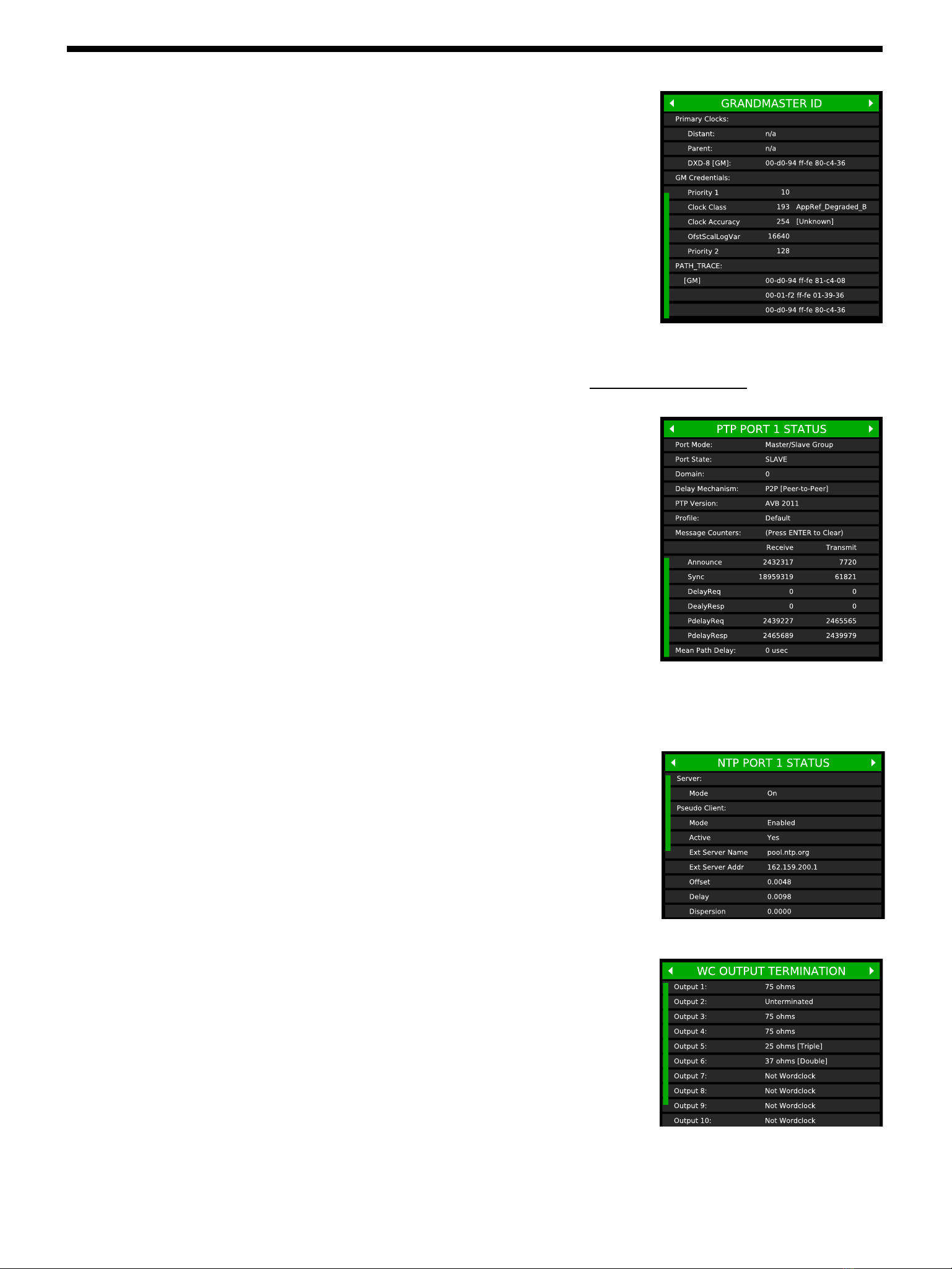
•GRANDMASTER ID
-Primary Clocks:
Three separate Primary Clock ID’s are displayed:
•DISTANT: When the DXD is locked to a Boundary clock, the distant clock
is a master clock ‘upstream’ from the boundary clock.
•PARENT: The clock id of the device the DXD is locked to.
•DXD-8: The clock id of this unit, with [GM] when it is the Grandmaster.
-Grandmaster Credentials:
Parameters used by the BMCA to determine the Grandmaster clock:
-Path Trace:
When Path Trace is available (AVB & PTP 2.1), all the different boundary clocks that the Announce message
traversed are displayed, up to the grandmaster (see ch 27 for information on PTP Clock ID).
•PTP PORT STATUS (1 page for each port)
-PTP Port Status Information:
-Message counters display the number of messages received and transmitted
by the port. Those are running counters and can be cleared by pressing the
ENTER key.
Monitoring the messages exchanged is useful when troubleshooting.
Announce and Sync messages for example are sent by Master devices. Delay
Request & Delay Response (E2E) or Pdelay Request & Pdelay Response (P2P) will show PTP activity between devices.
-Mean Path Delay is the mean travel time of PTP packets between master and slave. The Mean Path Delay is displayed in µsec.
•NTP PORT STATUS (1 page for each port)
-Server Mode
-Pseudo Client Mode
-Message Counters:
•WORKD CLOCK OUTPUT TERMINATION
For each BNC output set to Wordclock, the DXD deduces the apparent value of
the termination resistance that is present at the far end of the attached cable. The
WC OUTPUT TERMINATION page displays the results of these calculations in
ohms. If the output is correctly terminated, the value displayed will be 75Ω. If the
measurement is in the area of 37.5Ω, ’[Double]’ is displayed alongside the value,
indicating that the line has apparently been terminated twice. Similarly, if in the
area of 25Ω, ‘[Triple]’ is displayed. When no termination is detected,
’Unterminated’ is shown. When an output is set for a signal other than
Wordclock, ‘Not Wordclock’ appears.
Additional status pages will appear with installed options such as GPS. See corresponding manual for details.
Note: Display has been enlarged to show all scrolling options
Note: Display has been enlarged to show all scrolling options
•the mode of the port
•the PTP State
•the domain number
•the delay mechanism
•the PTP version
•the PTP profile
•Announce
•Sync
•Delay Request
•Delay Response
•P Delay Request
•P Delay Response
•Priority 1
•Clock Class
•Clock Accuracy
•OfstScalLogVar
•Priority 2
•Kiss-o’-Death
•Symm. Active
•Symm. Passive
•Client
•Server
•Broadcast Server
•Broadcast Client
DXD-16 User Manual (rev 3.00)
Page 13
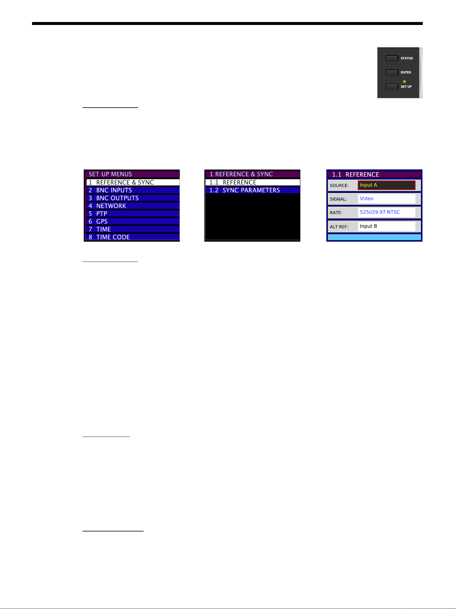
6.3 Set Up Mode
In Set Up mode, all parameters are accessible and can be changed by the user via the front panel.
To enter the Set Up mode, press the [SET UP] button. The Set Up LED lights up. To exit the Set Up mode,
press the [SET UP] key again and confirm that the Set Up LED is off.
6.3.1 MENU LEVELS
The Set Up mode has different levels. Typically, levels 1 & 2 are SELECT levels, made up of lists of menus organized in logical
groups. The number of SELECT levels varies from 1 to 3 depending on the menu. For example, menu 8 (Presets) only has 1
SELECT level and menu 4 (Networks) has 3. The last level is the SET level, where parameters are set and saved.
!SELECT LEVEL 1!!SELECT LEVEL 2! ! SET LEVEL
6.3.2 NAVIGATION
The navigation keys have different functions depending on the level.
• SELECT LEVELS (1, 2 or 3)
•Use the [UP] and [DOWN] buttons to select a menu from the list. The current selection is highlighted (black letters,
white background). Pressing the [down] button passed the lowest item on the list rotates back to the top of the list.
•Press the [NAV ▶] button to navigate to the next level.
•Press the [◀BACK] button to go back to the previous level.
• SET LEVEL
•Use the [NAV ▶] button to navigate to the next field. The currently selected field is highlighted (yellow letters on black
background). Pressing the [NAV ▶] button passed the last field on the page rotates back to the first one.
•Use the [UP] or [DOWN] buttons to change the value of the selected field.
•Use the [◀BACK] button to go back to the previous Level and exit the current one.
6.3.3 ENTER KEY
After modifying a value, a red border around the edited field appears. To save this new value, press the [ENTER] key. After the
[ENTER] key is pressed, the red border disappears, indicating the modification has been saved.
If the cursor is moved to another field without pressing the [ENTER] key first, the red border remains indicating a change was
made but not saved yet.
To exit the Set Up mode without making any change, press the [SET UP] key without pressing the [ENTER] key. Note that exiting
the SET Level by pressing the [◀BACK] key without pressing the [ENTER] key first also causes unsaved changes to be lost.
6.3.4 STATUS VALUES
In the SET level, the line at the bottom of the display (light blue background) indicates status values. Status values are the
values actually obtained, based on a menu selection.

Page 14
DXD-16 User Manual (rev 3.00)
6.3.5 MENU GROUPS
In the current firmware revision, menus are organized in 9 separate groups:
•1. REFERENCE & SYNC
•1.1 Reference
•1.2 Sync Parameters
•2. BNC INPUTS
•2.1 BNC Input A Set Up
•2.2 BNC Input B Set Up
•3. BNC OUTPUTS
•3.1 BNC Outputs 1-4
•3.2 BNC Outputs 5-8
•3.3 BNC Outputs 9&10
•3.4 BNC Outputs 11&12
•3.5 BNC Outputs 13&14
•3.6 BNC Outputs 15&16
•3.7 Audio Base Rate A
•3.8 Audio Base Rate B
•3.9 Mute On Unlock
•3.10 Delay/Advance 1 - 4
•3.10 Delay/Advance 5 - 8
•3.10 Delay/Advance 9 & 10
•3.10 Delay/Advance 11 & 12
•3.10 Delay/Advance 13 & 14
•3.10 Delay/Advance 15 & 16
•4. NETWORK
•4.1 Net 1
•4.2 Net 2
•4.3 Net 3
•4.4 Net 4
•4.5 Advanced Networking
•5. PTP
•5.1 Port Modes
•5.2 Grandmaster (Group)
•5.3 Port 1 (Controls, Timing, Independent Master, Time Jam)
•5.4 Port 2 (Controls, Timing, Independent Master, Time Jam)
•5.5 Port 3 (Controls, Timing, Independent Master, Time Jam)
•5.6 Port 4 (Controls, Timing, Independent Master, Time Jam)
•6, NTP
•6.1 Server Mode
•6.2 Pseudo Client Mode
•6.3 External Server Name A
•6.4 External Server Name B
•6.5 Poll Timing
•7. GPS
•7.1 Satellites Selections
•7.2 GPS Settings
•7.3 Advanced GPS Settings
•8. TIME
•8.1 Time Standards
•8.2 Real Time Clock
•8.3 Time & Date Display
•8.4 Leap Seconds
•9. TIME CODE
•9.1 SMPTE 2059 Set Up
•9.2 TC Generator 1
•9.3 TC Generator 2
•10. GPIO
•10.1 GPIO Inputs
•10.2 GPIO Outputs
•11. PRESETS
•12. UTILITY
•12.1 Brightness
•12.2 Control Lockout
•12.3 Clear Memory
•12.4 Reboot
•12.5 Feature Keys
•12.6 Name
For detailed description of all the parameters and settings in each of these menus, go to chapter 7.

DXD-16 User Manual (rev 3.00)
Page 15
7. M e n u s D e s c r i p t i o n
7.1 R e f e r e n c e
7.1.1 R E F E R E N C E ( M E N U 1.1 )
Menu 1.1 lets you select one of the following sources to be used as the DXD-16’s reference:
!- Internal
- BNC Input A
- BNC Input B
- PTP Mode
- GPS (available only with the optional GPS receiver - for information, see DXD/GPS users manual)
•INTERNAL is the DXD-16 oscillator (TCXO); if the OCXO option is installed, INTERNAL automatically uses the OCXO
oscillator and the display indicates ‘Internal/OCXO’.
•BNC INPUTS A and B are defined in menus 2.1 and 2.2
•PTP Mode is a little different. Selecting PTP Mode as the reference is required for the DXD-16 to be a PTP slave, i.e.
‘referenced’ to an external PTP Grandmaster. However, selecting PTP Mode means that the DXD-16 ports set to ‘Master/
Slave Group’ will participate in the PTP Grandmaster selection based on the BMCA (see 15.5). Explanatory text has been
added to the REFERENCE select menu when PTP Mode is activated.
NOTE: When PTP Mode is selected, at least one of the ports needs to be set to ‘Master/Slave Group’ (menu 5.1). If not,
the DXD will lock to its internal crystal and a warning message will appear on the display (see 26.Troubleshooting). The
LOCK bar at the bottom of the Main Rotation display will also indicate NO PORT.
Additional Fields: Depending on which reference was selected, additional fields will appear below the SOURCE field:
•SIGNAL and RATE: when selecting Input A or Input B, these status field indicate the signal type and the rate of the
selected reference, as defined in menus 2.1 and 2.2.
•ALTERNATE REFERENCE: when BNC INPUT A has been selected as the reference, BNC INPUT B can be set as an
alternate source to be used as a fail-safe back up. Note that, to guarantee a smooth transition, both sources must have
the same format and rate. For more on Alternate Reference, see chapter 10.
Note that, if there is no alternate reference, the DXD-16 will always revert to INTERNAL if the reference disappears.
•LOCAL REF WHEN GM: when PTP Mode is selected, if the optional DXD/GPS receiver has been installed, this fields
enables the GPS to be set as the reference when the DXD-16 is the Grandmaster, giving the DXD-16 a better chance
being selected by the algorithm.
There are no additional fields when the reference source is ‘INTERNAL’ or ‘GPS’.

Page 16
DXD-16 User Manual (rev 3.00)
7.1.2 SYNC PARAMETERS (MENU 1.2)
Several parameters are available in this menu that control the way the DXD synchronizes.
•BNC INPUT COLOR FRAMING: color framing synchronization to video inputs can
be enabled in this menu. “CF” indication will appear in the main rotation reference
line when enabled and locked.
•BNC INPUT TIME JAM SOURCE: Selects the source of a Time Jam (see 8.2).
•BNC INPUT TIME JAM RESYNC: Used for a manual Time Jam (see 8.2)
•PTP JUMP THRESHOLD: When the difference between the internal TOD and the PTP reference is above the value
entered, the DXD will not attempt a smooth transition (slew) but will instead jump instantly to the new time.
Value can be adjusted from 5 msec to 15 sec, or set to ‘Never’. Default value is 5#msec.
7. 2 B N C I n p u t s
7.2.1 BNC INPUT A SET UP (MENU 2.1)
The 2 BNC Universal inputs can accept WC, AES (AES-3id unbalanced), 10 MHz and video sync (HD & SD - see Appendix A
for a list of supported video inputs). Menu 2.1 lets you select the type of input connected to BNC INPUT A and its rate.
•SIGNAL: WC, AES, 10 MHz or Video Sync
•LEARN/SET: LEARN is the default value. With LEARN, the DXD-16 determines the incoming rate; with SET, the user
determines the incoming rate. For more information on LEARN vs. SET, go to Chapter 9.
•RATE: If LEARN is selected, the rate field is Status only (pale Blue) and cannot be changed. If SET is selected, the user
can select a rate from a list, based on the type of Signal selected.
7.2.2 BNC INPUT B SET UP (MENU 2.2)
Menu 2.2 is identical to menu 2.1 for BNC Input B except for the following.
If BNC INPUT B is set up differently than BNC INPUT A, a warning message appears on the bottom line: ‘ALT REF
INCOMPATIBLE’.
As mentioned above, to switch smoothly between 2 different sources in the event of a reference failure, these must be identical
(see chapter 10 for more information on Alternate Reference).
7.3 BNC Outputs
The DXD-16 generates 6 different reference signals simultaneously, each of them sent to a different group of BNC outputs, as
described below. Each of these universal output groups can output WC, AES, Video Sync or 10MHz.
7.3.1 BNC OUTPUTS 1-4 (MENU 3.1)
Menu 3.1 defines BNC outputs 1-4
•SIGNAL : this field defines the type of signal generated (WC, AES, 10 MHz or Video Sync).
Based on the signal selected, additional fields appear to define more parameters:
•Audio (WC or AES)
-BASE & MULT: Base Rates A or B as defined in menus 3.7 or 3.8 followed by a multiplier (x1, x2, x4, x8)
-ACTUAL: The actual rate will be indicated in blue letters (status info).

DXD-16 User Manual (rev 3.00)
Page 17
•Video Sync (SD & HD)
-RATE: select a video rate from a list (see appendix A).
•10MHz
-no additional field.
7.3.2 BNC OUTPUTS 5-8 (MENU 3.2)
Menu 3.2 is identical to menu 3.1 for BNC outputs 5-8.
7.3.3 BNC OUTPUTS 9&10 MENU (3.3)
Menu 3.3 is identical to menu 3.1 for BNC outputs 9&10.
7.3.4 BNC OUTPUTS 11&12 (MENU 3.4)
Menu 3.4 is identical to menu 3.1 for BNC outputs 11&12.
7.3.5 BNC OUTPUTS 13&14 (MENU 3.5)
Menu 3.5 is identical to menu 3.1 for BNC outputs 13&14.
7.3.6 BNC OUTPUTS 15&16 (MENU 3.6)
Menu 3.6 is identical to menu 3.1 for BNC outputs 15&16.
7.3.7 AUDIO BASE RATE A (MENU 3.7)
For audio outputs (Word Clock or AES), two different base rates are available, labeled Audio Base Rate A & B. Menu 3.7
defines Audio Base Rate A.
•SET/AUTO: SET is the default value; AUTO is a special function, available only when the input reference is an audio signal.
With AUTO, the DXD-16 automatically determines the incoming rate and uses that as the base rate. The advantage is that, if
the rate of the input reference changes, so does the generated output, automatically.
•RATE: If SET was selected, a rate can be selected form a list that includes 32K, 44.1K and 48K + all the pull coefficients (see
appendix B). If AUTO was selected, the measured rate of the reference is displayed here (status only).
Note that, with AUTO selected, if the rate of the input reference is a multiple of one of the basic rates, 96K for example, the
basic rate will be used instead, 48K in this example.
•VSO/CENTS: VSO (Variable Speed Oscillator) was used to vary the speed of old analog tape machines. This function,
when activated, allows to vary the rate of the audio outputs, and thus the pitch. As this function is mainly used for musical
applications, the speed adjustment is measured in cents (semi tone/100). The VSO range is +/- 200 cents, i.e. 2 whole tones
(+12.2562% to -10.9101%). When VSO is on, the letters ‘VSO’ appear on the display next to the rate in the OUTPUTS main
rotation page
NOTES: When adjusting the VSO cents value in the menu, the changes take effect immediately. There is no need to
press [ENTER] for every speed change.
7.3.8 AUDIO BASE RATE B (MENU 3.8)
Menu 3.8 is identical to menu 3.7 for Audio Base Rate B.
7.3.9 MUTE ON UNLOCK (MENU 3.9)
To guarantee that the BNCs do not output any signal before the DXD achieves lock, which could cause issues with the
receiving equipment, menu 3.9 lets you mute the outputs while unlocked.
On = mute - Default value is off.
Each of the 6 output groups can be set independently: 1-4 / 5-8 / 9&10 / 11&12 / 13&14 / 15&16.

Page 18
DXD-16 User Manual (rev 3.00)
7. 3 .10 D E L AY / A DVA N C E 1 - 4 ( M E N U 3 .10 )
This menu enables to delay or advance WC, AES or Video Sync out of this group of BNC outputs (1-4) by a set amount.
•ENABLE: Choices are Off / Delay / Advance. Selecting DELAY or ADVANCE will delay or advance the signal by the
amount entered in the next field.
If the signal selected for this output group does not support this function (10MHz or Time Code), the display will say
‘Unavailable for signal’ in blue letters indicating it cannot be changed.
•MICRO SECONDS (USEC): The offset value in micro seconds is made up of 5 separate fields, the one on the far
right for µsec, the one on the far left for the tens of msec.
The offset can vary from 1µsec (or 00001 µsec) to 99999 µsec (or 99.999 msec).
•CLEAR: To clear the value in the field above, toggle to ‘PRESS ENTER TO CLEAR’ and press the ENTER key.
Acknowledgment on the OUTPUTS Page of ADVANCE/DELAY activation
The OUTPUTS page on the main rotation display will indicate that a BNC output signal has been advanced or delayed
by replacing the blue rectangle with the output format in the right column of the corresponding output group by a red
rectangle.
In the illustration above, Outputs 9 & 10 are either delayed or advanced.
Note that even if the value entered in the Delay/Advance menu is ’00,000’, the red rectangle will still be show up on
the display. To return to blue, the feature must be turned off (i.e. the ENABLE field must be set to OFF).
7. 3 .11 D E L AY / A D VA N C E 5 - 8 ( M E N U 3 .11 )
Menu 3.11 is identical to menu 3.10 for BNC outputs 5-8.
7.3.12 DELAY/ADVANCE 9 & 10 (MENU 3.12)
Menu 3.12 is identical to menu 3.10 for BNC outputs 9&10.
7.3.13 DELAY/ADVANCE 11 & 12 (MENU 3.13)
Menu 3.13 is identical to menu 3.10 for BNC outputs 11&12.
7.3.14 DELAY/ADVANCE 13 & 14 (MENU 3.14)
Menu 3.14 is identical to menu 3.10 for BNC outputs 13&14.
7.3.15 DELAY/ADVANCE 15 & 16 (MENU 3.15)
Menu 3.15 is identical to menu 3.10 for BNC outputs 15&16.

DXD-16 User Manual (rev 3.00)
Page 19
7. 4 N e t w o r k
The Network menu has 4 identical and separate sub-menus, one for each of the DXD-16 ports.
7. 4 .1 N E T 1 ( M E N U 4 .1 )
7.4.1.1 NET 1 IP ADDRESS (MENU 4.1.1)
Menu 4.1.1 includes fields for DHCP, IP Address, Subnet Mask and Gateway.
DHCP stands for Dynamic Host Configuration Protocol. When on, the DHCP server automatically assigns an IP
address. The values in the 3 other fields (IP address, Subnet Mask & Gateway) are in blue, indicating status only.
When DHCP is off, these parameters must be entered manually. They are expressed in dot-decimal notation made
up of 4 numbers ranging from 0 to 255, separated by dots.
The bottom line on the display (blue background) indicates the current IP address.
Note that, when transitioning DHCP from Off to On, a reboot will be required and a
message will indicate so in the display. But if DHCP was in effect at power up, but
there was no cable plugged in, the DHCP acquisition process can be re-initiated at a
later time by simply hitting the Enter key when viewing the IP ADDRESS menu.
7.4.2 NET 2 (MENU 4.2)
7.4.2.1 NET 2 IP ADDRESS (MENU 4.2.1)
Menu 4.2.1 is identical to menu 4.1.1 for Net 2.
7.4.3 NET 3 (MENU 4.3)
7.4.3.1 NET 3 IP ADDRESS (MENU 4.3.1)
Menu 4.3.1 is identical to menu 4.1.1 for Net 3.
7.4.4 NET 4 (MENU 4.4)
7.4.4.1 NET 4 IP ADDRESS (MENU 4.4.1)
Menu 4.4.1 is identical to menu 4.1.1 for Net 4.
7.4.5 ADVANCED NETWORKING (MENU 4.5)
7.4.5.1 INTERNAL VLAN ID’S (MENU 4.5.1)
In an effort to filter out unwanted multicast receive packets, the DXD-16 makes use of
two internal VLAN Id’s.
The DXD-16 will never tag any transmitted packets with these VLAN Id’s. However, care
should be taken that the DXD-16 should not receive VLAN-tagged packets using these Id’s.
While it is highly unlikely that this situation will arise, if there is any possibility that it
will, then either the VLAN Id’s should be changed at their source, or the DXD-16
internal VLAN Id’s should be changed so that the match does not occur.
Menu “4.5.1 INTERNAL VLAN ID’S” enables the operator to change the 2 internal VLAN id’s. A re-boot is required
after any change to these menus.
Default ID values are 1 and 2.
7.4.5.2 DSCP TRANSMIT VALUES (MENU 4.5.2)
In the header of each IP packet on a network is found a DSCP (Differentiated Services Code Point) value, which is a
number between 0 and 63. Higher values generally infer higher priority, but IT Managers are able to use these values
in various ways to classify and enhance traffic flow. Such methods however are beyond the scope of this manual.
PTP protocol uses two types of messages: “Event” messages, which are timestamped, and “General” messages which
are not. Event messages should run with priority greater or equal to that of General messages.

Page 20
DXD-16 User Manual (rev 3.00)
Annex D of IEEE Std 1588-2008 (aka PTPv2) specifies the following: “For PTP event messages, the value of the
differentiated service (DS) field in the Type of Service (ToS) field should be set to the highest traffic class selector
codepoint available.”
AES67-2013 specifies a default DSCP value for most PTP messages, Event and
General, of decimal 46 (aka EF or Expedited Forwarding). SMPTE ST 2059-2:2015
does not include default DSCP values in its PTP Profile specification.
For PTP message transmission, the DXD-16 uses default values of 56 for Event
messages and 46 (EF) for General messages. These values may be changed however
in Menu 4.5.2.
7.5 PTP
This chapter describes the PTP menu settings. For general information on PTP, go to chapter 15.
7.5.1 PORTS MODES (MENU 5.1)
Each of the 4 DXD-16 ports can be set as:
-Master/Slave group
-Independent Master
-Time Jam (BNC Input)
-Disabled
-‘Master/Slave group’ is the default setting and is typically used to set
the DXD-16 as a boundary clock where one port would be slave to an
external grandmaster and the others masters to what is ’downstream’,
i.e. what is connected to that port (see first diagram in chapter 16). This
master/slave set-up could change as the BMCA determines which is the
grandmaster. Like a Boundary Clock, ports on a Group are all on the
same domain.
Unlike a Boundary Clock, a Group does not require one of the ports to
be a slave. If a reference other than PTP is selected in menu 1.1, a
message at the bottom of menu 5.1 will indicate “Master-only while Reference not PTP” and all ports in the group will be
Master-only. If the BMCA elects another unit as the PTP Grandmaster, those ports become PASSIVE.
Note that, per IEEE 1588, if multiple ports of a boundary clock
communicate to the same communication path (i.e. “see” each other),
the boundary clock shall place all of the involved ports in the PASSIVE
state, except the port with the lowest portNumber. This rule applies to
the group setting (see ch. 12 on PTP Ports States).
-Ports set to ‘Independent Master’ can only be PTP Masters, not slaves,
and are not part of the group. They are all on separate PTP domains. If
the BMCA elects another unit as the PTP Grandmaster for that domain,
this port becomes PASSIVE.
-Ports set to ‘Time Jam (BNC Input)’ will forward time information from a PTP master to the TOD (see Time Jam ch 8.2).
To view the state of the PTP ports, go to the PTP Ports page of the main rotation display (see 6.1.2).
7.5.2 GRANDMASTER [GROUP] (MENU 5.2)
This menu lets you set the following fields for all the ports set to ‘Master/Slave group’.
• Domain:!0 to 127; default = 0
• Priority 1:!0 to 255; default = 128
• Priority 2:!0 to 255; default = 128
Priorities are used in the BMCA to select the grandmaster - lower values have a
higher priority.
An equivalent menu exist for each port set the ‘Independent Master’ (menus 5.3.3…)
SWITCH 1
STUDIO A
GRANDMASTER
SWITCH 2
STUDIO B
SWITCH 3
STUDIO C
SWITCH 4
STUDIO D
M M M M
S
S
S
S
S
S
S
S
S
S
S
S
S
S
S
S
S
S
S
S
S
S
S
S
S
S
S
S
Independent Masters
SWITCH 2
STUDIO B
MMMS
SWITCH 1
STUDIO A
S
S
S
S
S
S
S
SWITCH 3
STUDIO C
M
GRANDMASTER
S
S
S
S
S
S
S
S
S
S
S
S
S
S
Master/Slave Group
Other manuals for DXD-16
2
Table of contents
Other Brainstorm Electronics Media Converter manuals


