Branick 130 Use and care manual

Branick Industries, Inc. •4245 Main Avenue •Fargo, North Dakota 58103
REV081914 P/N: 81-0257
Installation, Operation
& Repair Parts
Information
MODEL 130
NITROGEN INFLATION
CART

1

2
TABLE OF CONTENTS _______________________________________________________
SAFETY INSTRUCTIONS 2
DEFINITIONS 2
SPECIFICATIONS 3
INTENDED USE 3
COMPONENT IDENTIFICATION 4
SET-UP INSTRUCTIONS 5
OPERATING INSTRUCTIONS 6
TROUBLESHOOTING/DIAGNOSTIC 7
MAINTENANCE 8
REPAIR PARTS 9
REPAIR PARTS LIST 10
WARRANTY 11
SAFETY INSTRUCTIONS _____________________________________________________
▪NEVER allow unauthorized personnel to operate this product.
▪NEVER use this product for anything other than its intended use.
▪THOROUGHLY train new employees in the proper use and care of this product.
▪PROHIBIT unauthorized personnel from being in shop area while this product is in use.
DEFINITIONS _______________________________________________________________
▪CAUTION: Indicates a potentially hazardous situation, which if not avoided, may result in damage to
property or minor personal injury.
▪HAZARD: A source of potential injury to a person.
▪MAINTENANCE: Those actions that preserve the correct and proper conditions under which the machine
shall be used. This may include adjustment, replacement of wear items, lubrication and cleaning, but not
modifications or repair of damage.
▪MAY: This word is understood to be permissive.
▪MUST: This word is understood to be mandatory.
▪OPERATION: The correct and proper use of the machine as described in this manual.
▪SAFETY ALERT SYMBOL: A symbol that indicates a potential personal safety hazard. It is composed of
an equilateral triangle surrounding an exclamation point.
▪SHALL: This word is understood to be mandatory.
▪SHOULD: This word is understood to be advisory.
▪WARNING: Indicates a potentially hazardous situation, which if not avoided, may result in death or

3
SPECIFICATIONS ___________________________________________________________
Operating Temperature -4° to 158° F (-20° to 70° C)
Max Inflation Pressure 145 psi (10.0 bar)
Max Inlet Pressure 217 psi (15 bar)
Digital Inflator Accuracy +/- 0.5% of full scale reading
Display Increments 1 psi (0.1 bar)
Dimensional data 20 x 22.5 x 59 in (51 x 57 x 150 cm)
Weight 80 lbs (36 kgs)
Shipping Weight 100 lbs (45 kgs)
INTENDED USE _____________________________________________________________
The Nitrogen Inflation Cart is a pneumatic device designed to provide deoxygenated air for the purpose of inflating
vehicle tires.
___________________________________________________________________________
WARNING
This product is designed for use with a high pressure nitrogen tank. Ensure that a fully functional
regulator is installed on the tank and a tank key is kept with the cart.
___________________________________________________________________________
CAUTION
Before using this product, read and fully understand the operating
instructions and all decals on the product. This is necessary to
prevent injury to the operator and damage to the product.
Do not attempt to use this product for anything other than its
intended purpose.
Use of this product should be in a suitably ventilated shop.
Ensure tank is properly secured before use.
Do not use this product if it is visibly worn, distorted or damaged.

4
1
2
3
5
6
4
7
COMPONENT IDENTIFICATION ________________________________________________
________________________________________________________________________
1 Inflator Control Board
2 Power Switch
3 Battery Charge Indicator
4 Inlet Port
5 Fill Control Valve
6 Battery Charge Input
7 Outlet Ports
___________________________________________________________________________

5
SET-UP INSTRUCTIONS ______________________________________________________
1. Unpack and remove unit from shipping carton and pallet.
2. Inspect the unit for any visible damage.
Bottle set-up
1. Attach tank brackets to cart body using included hardware (Fig
1).
2. Attach one end of each tank strap to the tank brackets (Fig 2).
3. Place the nitrogen tank on the cart’s tank support. Do not let the
tank stand unsupported.
4. Attach other end of each tank strap to tank brackets. Pull on loose end of tank
strap to tighten securely against tank (Fig 3). Tank should be held firmly with no
play (Fig 4).
5. Connect N2 input line to the inline filter using a gas tight 1/4” NPT male
fitting. Connect other end of hose to regulator on tank.
6. Connect output hoses to output ports and coil onto hangers.
Generator set-up
1. Connect hose from existing generator to cart’s inline filter using a gas
tight 1/4” NPT male fitting.
2. Connect output hoses to output ports and coil onto hangers.
Power Requirements & Charging Instructions
▪The system is powered by an internal Sealed Lead Acid (SLA) 12 volt
rechargeable battery.
▪Charge system by plugging the included charger cord into the charger
socket on the front of unit, and the other end into a 110/120 volt outlet.
▪Charging a completely flat battery could take up to 7 hours to obtain a full
charge.
▪The length of battery charge is dependent upon many factors including
use, how often charged, etc. But once fully charged, the system should
provide up to 8 hours of continuous inflation/deflation.
▪Under no circumstances should battery be left in flat state designated by
a blank display or diagnostic code “LO”.
Figure 1
Figure 2
Figure 3
Figure 4

6
1
2
3
4
DIGITAL INFLATOR OPERATING INSTRUCTIONS ________________________________
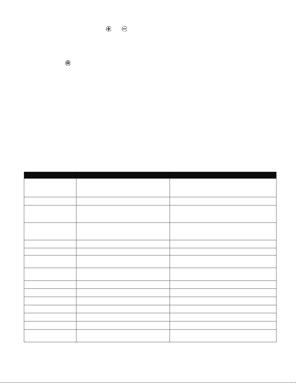
___________________________________________________________________________
1 Decrease Key
2 Increase Key
3 Top-Off Key
4 Nitrogen Purge Cycle Key
___________________________________________________________________________
Converting Air Filled Tires to Nitrogen
1. Turn the Fill Control Valve handle to the STOP position and flip the ON/OFF button to turn on power.
2. Connect the output hoses to the valve stems of the tires and ensure that leaks do not exist.
3. Set the tire pressure with the and buttons on the front panel.
Note: The target pressure should be the vehicles recommended tire pressure found on the sticker inside
the driver’s door jamb or inside the fuel access door.
4. Turn the Fill Control Valve handle to FILL.
5. Press the button to start the nitrogen conversion.
6. When the alarm sounds the cycle is complete.
7. Turn the Fill Control Valve handle to STOP and remove hoses from valve stems.
8. Flip the ON/OFF button to turn inflator off.
Filling Tires to Two Different Pressures
Some vehicles require two different tire pressure settings from the front tires to the rear. In this example, the front
tires require 32 psi while the rear tires require 40 psi.
1. Go through steps 1 through 6 above in “Converting Air-filled Tires to Nitrogen” using the lowest of the two
pressures (32 psi) as the target pressure.
2. After finishing step 6, turn Fill Control Valve handle to STOP. Disconnect the hoses from the tires that are
at their final pressure (in this example the front tires are at 32 psi).
3. Change the target pressure for the remaining two tires using the or buttons (in this example press
the button to 40 psi).
4. Turn the Fill Control Valve handle to FILL position.
5. Press the button.
6. When the alarm sounds the cycle is complete.
7. Turn the Fill Control Valve handle to STOP and remove hoses from valve stems.
8. Flip the ON/OFF button to turn inflator off.
To Top-off Tires Already Filled with Nitrogen
1. Turn the Fill Control Valve handle to the STOP position and flip the ON/OFF button to turn on power.
2. Connect the output hoses to the valve stems of the tires and ensure that leaks do not exist.

7
3. Set the tire pressure with the and buttons on the front panel.
Note: The target pressure should be the vehicles recommended tire pressure found on the sticker inside
the driver’s door jamb or inside the fuel access door.
4. Turn the Fill Control Valve handle to FILL.
5. Press the button.
6. When the alarm sounds the cycle is complete.
7. Turn the Fill Control Valve handle to STOP and remove hoses from valve stems.
8. Flip the ON/OFF button to turn inflator off.
Emergency Stopping
Stop the inflation / deflation cycles by pressing any button on the front panel or by turning the Fill Control Valve
handle from FILL to STOP.
Additional Application Modes
The inflator software contains two other fill modes, ‘Std’and ‘tir’, that are not applicable to nitrogen inflation. If one
of these modes is accidentally entered, the system will not purge tires before filling. Please call our customer
service line for assistance
TROUBLESHOOTING / DIAGNOSTIC CODES_____________________________________
The following diagnostic codes are reported via the inflator display.
Problem / Code
Possible Cause
Solution
Hose connectors leak or
will not seal to the valve
stem
Hose Connectors are worn
Replace connectors
No Display
No power connected
Switch power on / Plug in / Replace Battery
Inflation process starts
but does not complete
Low supply pressure or leaks exist
Check supply pressure and confirm leaks do
not exist
Inflation or deflation is
very slow
Inline filter or mesh filters at input or output
ports may be clogged
Clean or replace filters
E1
Unstable or insufficient supply pressure
Check supply pressure
E4
Over inflation due to blocked hose
Remove blockage or replace hose
E5
Unit powered ON under pressure; i.e., hose is
connected to tire and control valve set to FILL
Rotate control valve to STOP and cycle the power
ON/OFF again
E6, E8, E9
Pressure sensor error
Contact Customer Service 800-437-4394
E10 or LO
Under voltage
Plug in power cord and charge battery
E11
Over voltage
Check power supply
E12
PCB fault
Contact Customer Service 800-437-4394
E13
Lost or corrupted calibration settings
Contact Customer Service 800-437-4394
E17
Calibration data corrupted
Calibration is required. Contact Customer Service
E19
Capacitive touch interface error
Contact Customer Service
E18, E20,
E21,E22,E23,E28
Software error
Contact Customer Service

8
MAINTENANCE _____________________________________________________________
See repair parts breakdown for replacement parts.
ALWAYS: Keep Nitrogen Inflation System clean.
DAILY: Plug in System to Charge Battery
___________________________________________________________________________
OWNER’S RECORDS Date Installed: _______________________
Serial number _______________________
___________________________________________________________________________

9
REPAIR PARTS _____________________________________________________________

10
REPAIR PARTS LIST __________________________________________________
ITEM
QTY
PART NO.
DESCRIPTION
1
2
90-0004
Wheel, 8”
2
22
50-0125
1/4-20 X 5/8” Socket Button Head Screw
3
22
108-110
1/4 SAE Flat Washer
4
2
54-0053
1/8 X 2-1/2”Reusable Cotter Pin
5
1
41-0042
ON/OFF Rocker Switch
6
1
40-0063
12V Battery
7
1
40-0064
12V Charger
8
1
02-0023
Inflator with Harness
9
1
60-0208
1/2” NPT Ball Valve
10
2
60-0316
1/2" Tube X 1/4" NPT Male Connector Fitting
11
2
60-0177
1/2" Tube X 3/8”NPT Male Connector Fitting
12
1
60-0181
1/2" Tube X 1/2” NPT Male Elbow Fitting
13
2
028-307
#10-24 X 1 3/4” Phillips Head Machine Screw
14
6
055-127
#10-24 Nylon Hex Nut
15
2
06-0205
Tank Bracket
16
1
43-0048
Power Entry Module
17
1
42-0025
Power Harness
18
4
108-024
#10 SAE Washer
19
2
52-0049
5/8”SAE Washer
20
2
59-0084
Tank Safety Strap
*
21
1
59-0085
Velcro Battery Strap
22
1
60-0330
Manifold
23
4
50-0126
5/16-18 X 5/8”Socket Button Head Screw
24
4
108-123
5/16”SAE Washer
25
1
932-001
In-Line Filter
26
1
60-0191
3/8”Tube X 1/4" NPT Male Connector Fitting
27
4
62-0038
25' Hose Assembly
*
28
1
60-0192
1/4" NPT X 3/4-16 Straight Bulkhead Fitting
29
1
60-0107
1/2" NPT X 3/8 NPT Bushing
30
-
D20-006
3/8" O.D. Nylong Tube (Black)
31
-
D20-031
1/2" OD Tube (Black)
32
1
42-0027
Inflator Harness
*
33
1
60-0074
3/8”NPT Plug
34
1
60-0175
1/2" Tube X 3/8”NPT Male Elbow Fitting
35
1
81-0256
Instruction and Troubleshooting Guide Placard
*
36
6
60-0331
1/4" NPT Quick Connect Coupler
37
4
108-067
5/16” Lock Washer
38
4
60-0201
Clip-On Chuck
*
39
4
60-0332
1/4” NPT Quick Connect Nipple
*
40
1
42-0023
6’ Power Cord
*
* Items not shown

11
COMMERCIAL WARRANTY
This product is warranted by BRANICK INDUSTRIES, INC. to the original user-owner against defective materials
or workmanship for a period of one year from the date of shipment. During the warranty period, at the discretion of
Branick management, if the product is found to be defective, it will be repaired or replaced without charge. For
service, contact Branick (800-437-4394) to obtain an RMA. Any product shipped to Branick must have an RMA
and proof of original shipment date. The repaired or replacement product will be returned with transportation
charges prepaid by Branick.
This warranty does not cover defects in the product caused by ordinary wear and tear, abuse, misuse,
overloading, accident (including shipping damage), improper maintenance, alteration, or any other cause not the
result of defective materials or workmanship.
REPAIR OR REPLACEMENT IS THE EXCLUSIVE REMEDY FOR DEFECTIVE PRODUCT UNDER THIS
WARRANTY. THIS WARRANTY IS EXPRESSLY IN LIEU OF ALL OTHER WARRANTIES, INCLUDING ANY
IMPLIED WARRANTY OF MERCHANT ABILITY OR ANY IMPLIED WARRANTY OF FITNESS FOR A
PARTICULAR PURPOSE OF THIS PRODUCT. BRANICK INDUSTRIES, INC. SHALL NOT BE LIABLE FOR
ANY CONSEQUENTIAL OR INCIDENTAL DAMAGES.
BRANICK INDUSTRIES, INC. reserves the right to make changes in the design or construction of our products
without obligation to incorporate such changes in products already sold and without notice.
Service parts and regular repair service are available from authorized distributors of Branick products, or from:
BRANICK INDUSTRIES, INC.
4245 Main Ave.
Fargo, North Dakota 58103
Toll Free: 800-437-4394
© Copyright 2018 by Branick Industries, Inc. Printed in U.S.A.
Table of contents
Popular Outdoor Cart manuals by other brands

Ninebot
Ninebot Gokart Pro user manual

Harbor Freight Tools
Harbor Freight Tools 60570 Owner's manual & safety instructions

Broil King
Broil King DC2CART-1 installation instructions

Hilka
Hilka G301T7BBS Assembly instructions

Trinity
Trinity BASICS TBFPBR-1411 owner's manual

Chauvet
Chauvet NIMBUS Quick reference guide