Branson DCX V-Series User manual

© 2022 Branson Ultrasonics Corporation Page 1 of 2 4000842, REV. 01
DCX V-Series Power Supply - Quick Start Guide
Overview
This Quick Start guide is intended to help you with the basic installation and setup of
your new DCX V Power Supply.
Consult your power supply manual for detailed information on ventilation, environmen-
tal requirements, operating the power supply, accessing the web page interface, main-
tenance, and troubleshooting.
Location
The DCX V Power Supply is available in three different sizes. Two different form factors
allow for operating the power supply on a benchtop or mounted vertically:
Use the keyhole mounting bracket to mount the unit in the needed position. Use M6
(6mm) screws to mount the unit.
Dim. Inch mm Dim. Inch mm
a10.37 263 h5.22 132.6
b8.37 212.6 i4.5 114.3
c7.12 180.8 j3.5 89
d5.53 140.5 k15.75 400
e14.00 355.6 l3.62 91.9
f0.31 7.9 m2.62 66.5
g17.38 441.5 n1.31 33.3
Size Small Medium Large
Weight 15 lb (6.8 kg) 17 lb (7.7 kg) 21 lb (9.5 kg)
abc
d
e
f
h
i
g
l
m
n
3.0 in (76 mm) recommended
5.0 in (127 mm) recommended clearance for cables
fan clearance (both sides)
Benchtop Vertical
Back-mounted Side-mounted
j
k
Mounting
Plate
Small
Medium
Large
Connect the Power Supply
• Ensure the power source is disconnected before working on line connections
• Ensure the power switch on the back of the unit is in the OFF position before making any
electrical connections
• Always connect the power supply into a grounded power source
•Groundthepowersupplybysecuringan8gagegroundedconductortothegroundscrew
located next to the air outlet
• The power supply installation should only be performed by qualified personnel and in
accordance with local standards and regulations
1. Detach the connector block on the back of the power supply.
2. Use two properly sized wires (according to local standards) to connect a 24 VDC
2.5 A safety certified and agency approved power supply as shown.
3. Use three properly sized wires (No. 12 gage, 2.5 mm or according to local stan-
dards) to connect line 1, line 2, and ground to the connector block as shown.
Choose wires according to the current rating as specified on the label located on the
back of the unit. Be sure to use agency approved wiring and use sleeving or tubing
on each wire for double insulation.
4. Secure an 8 gage grounded conductor to the ground screw located next to the air
outlet.
5. Connect the converter-booster-horn stack to the power supply using the RF cable.
Ensure the end with the ferrite is connected to the power supply.
6. Ensure the power switch on the back of the unit is in the OFF position. Plug the con-
nector block back into the power supply. Tighten the two securing screws.
7. Connect the power supply to a single-phase, grounded, 3-wire, 50 or 60 Hz
200-240 V power source.
RF
Connector
L1
L2/N
GND
24VDC
24VR/0V
User I/O
Connector
Ground
Screw
Ethernet
Connector
Ferrite
Use Sleeving
or Tubing
On/Off
Switch
© 2022 Branson Ultrasonics Corporation Page 2 of 2 4000842, REV. 01
DCX V-Series Power Supply - Quick Start Guide
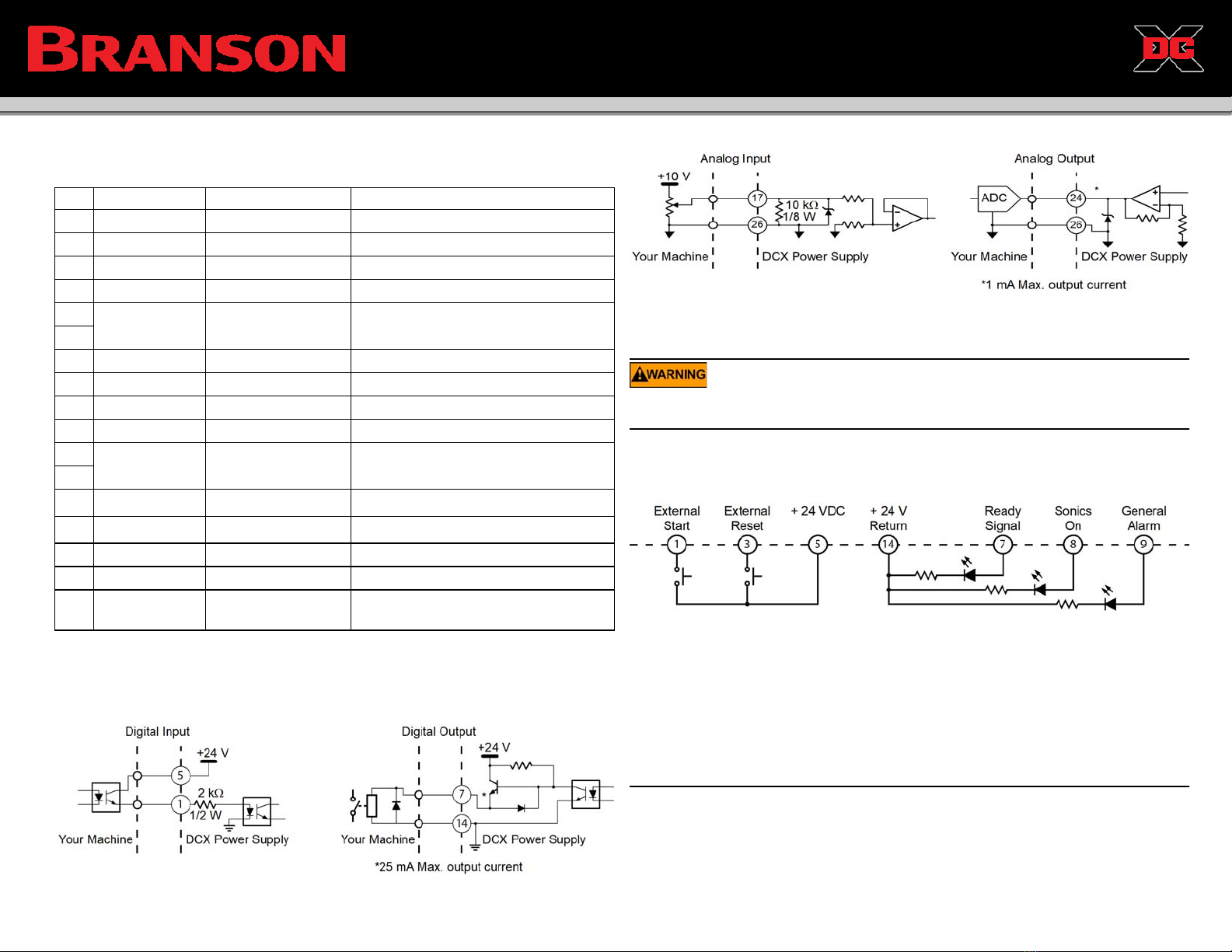
I/O Connections (26-pin HD D-Sub Connector)
Typical Digital I/O Wiring Examples:
User I/O Connector Pin Assignments*
* This table shows the default pin assignments. Pins 1-4, and 7-10 can be configured using the DCX
PIN I/O Type Function Values
1 Input Digital External Start Apply +24 VDC to run cycle
2 Input Digital External Seek Apply +24 VDC to perform a seek
3 Input Digital External Reset Apply +24 VDC to reset alarm
4 Input Digital Memory Clear Apply +24 VDC to clear memory
5I/O Signal
Source
+24 VDC (Customer
Supplied) +24 V (internally fused to 1.8 A)
6
7 Output Digital Ready +24 V indicates the system is ready
8 Output Digital Sonics Active +24 V indicates ultrasonics are active
9 Output Digital General Alarm +24 V indicates an alarm occurred
10 Output Digital Seek/Scan Out +24 V indicates Seek/Scan in progress
14 I/O Signal
Return
+24 VDC Return
and I/O Return
Return for all pins except pins 17, 18,
24, and 25
15
17 Input Analog Amplitude In 1 V to + 10 V (10 % to 100 %)**
web page interface. Consult your power supply manual for details on configuring digital I/O functions.
**If the input signals are not within their valid range, or if left unconnected, the power supply will use
50 % amplitude and zero frequency offset, respectively.
18 Input Analog Frequency Offset 1 V to + 9 V (5 V is zero offset)**
24 Output Analog Power Out 0 V to + 10 V (0 % to 100 %)
25 Output Analog Amplitude Out 0 V to + 10 V (0 % to 100 %)
26 Analog Signal
Return
Analog Signal
Return Return for pins 17, 18, 24, and 25
Typical Analog I/O Wiring Examples:
Test the Equipment
To test the power supply for proper operation, follow the steps listed below:
• Ensure that no one is in contact with the horn when testing the power supply
• Do not cycle the welding system if either the RF cable or converter is disconnected
1. Ensure the power supply is properly connected, as indicated in Section “Connect
the Power Supply” on page 1.
2. Wire the necessary I/O signals as shown or similar to the following diagram:
3. Turn on the power supply. The front panel Power and 24 V LEDs should turn on.
Ready Signal should become active. To avoid a power-on alarm, ensure 230VAC
are present for at least 1 second before supplying the 24VDC.
4. Send an External Start signal for 1-2 seconds. The Sonics Active output will become
active while the External Start signal is present. If the General Alarm output does not
become active, the test procedure is finished.
5. If the General Alarm output becomes active, send an External Reset signal and
repeat step 2 one time only. If the alarm persists consult your power supply manual.
DCX Web Page Interface Default IP Address:
IP address: 192.168.10.100 Subnet Mask: 255.255.255.0
Other Branson Power Supply manuals


