Branson 900M Series User manual

900M Series
Power Supplies
Controls
Control
Branson 900M
Status
Power
ontents of This Section
2.1 Introduction
2-1
2.2 900M Front Panel
2-1
Power Sub-Panel
2-2
Control Sub-Panel
2-3
Status Sub-Panel
2-4
2.3 900M Back Panel
2-6
2.1 Introduction
This section describes the functions of the 900M front panel keys, it does not explain how
to use the keys. This information is included in Section 4, Operation. The front panel
keys are arranged in three groups of sub-panels - Power, Control and Status. The sections
that follow describe the keys in the same three groupings. This information is followed by
descriptions of the back panel connectors and fuses, etc.
2.2 900M Front Panel
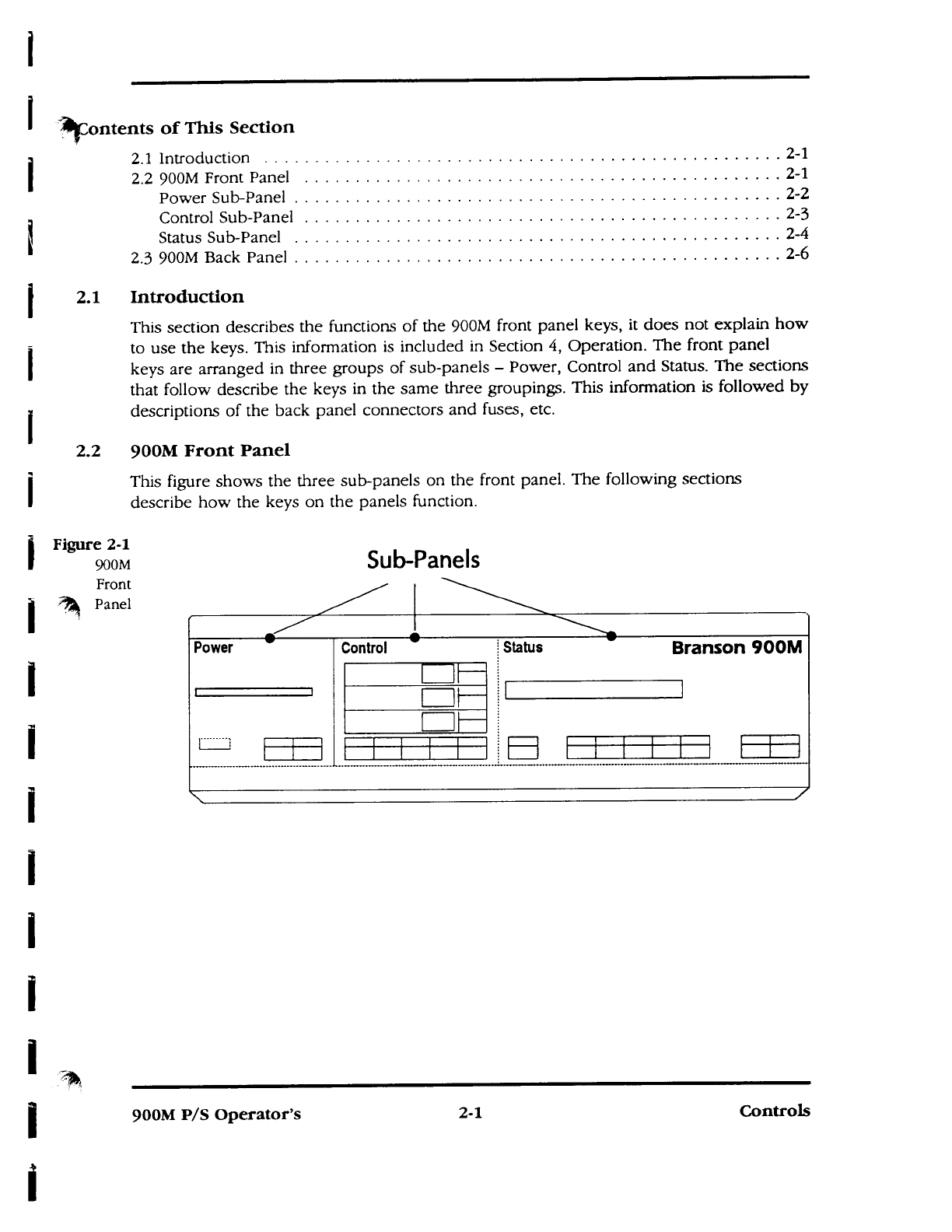
This figure shows the three sub-panels on the front panel. The following sections
describe how the keys on the panels function.
Figure 2-1
900M
Front
Panel
Sub-Panels
900M P/S Operator's
2-1
Controls
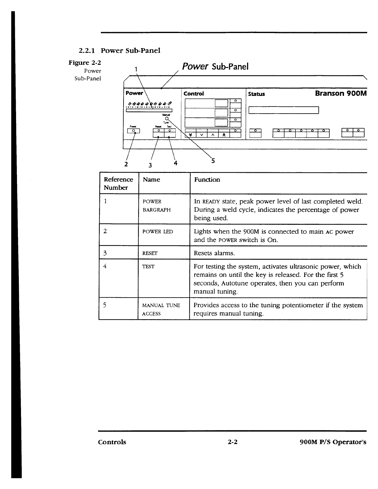
2.2.1 Power Sub-Panel
Figure 2-2
Power
Sub-Panel
1
Power
Sub-Panel
_
Power
Control
Status
Branson 900M
0
i
D
ower
Rased
Iasi
0
0 0
WMI
IMIEMBEF111
MIME
TN
V
V
A
A
3
\
4
N
5
Reference
Number
Name
Function
1
POWER
BARGRAPH
In
READY
state, peak power level of last completed weld.
During a weld cycle, indicates the percentage of power
being used.
2
POWER LED
Lights when the 900M is connected to main
AC
power
and the
POWER
switch is On.
3
RESET
Resets alarms.
4
TEST
For testing the system, activates ultrasonic power, which
remains on until the key is released. For the first 5
seconds, Autotune operates, then you can perform
manual tuning.
5
MANUAL TUNE
ACCESS
Provides access to the tuning potentiometer if the system
requires manual tuning.
Controls
2-2
900M P/S Operator's
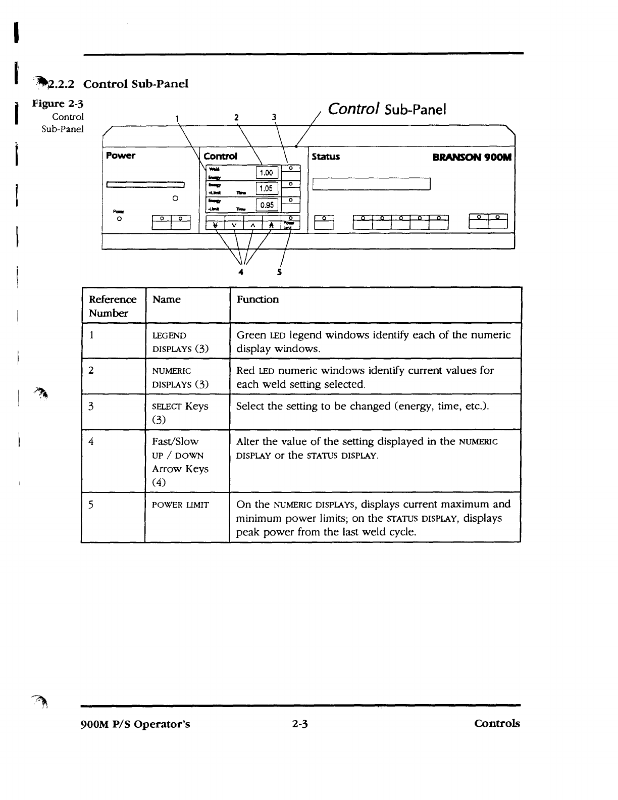
2.2.2 Control Sub-Panel
Figure 2-3
Control
Sub-Panel
2
3
Control
Sub-Panel
/
Power
\Control
\ \
Status
BRANSON 900M
Imp
1.00
°
Imp
Mink
Mrs
1.05
°
1
1
0
Pour
`Mg,
-Linit
Th.
0.95
0
o
0
0 0
0
0
o
o
iN;Mi
0
o
NMI
1
\ \
i /
7
4
5
Reference
Number
Name
Function
1
LEGEND
DISPLAYS
(3)
Green
LED
legend windows identify each of the numeric
display windows.
2
NUMERIC
DISPLAYS (3)
Red
LED
numeric windows identify current values for
each weld setting selected.
3
sm.Ecr Keys
(3)
Select the setting to be changed (energy, time, etc.).
4
Fast/Slow
UP / DOWN
Arrow Keys
(4)
Alter the value of the setting displayed in the
NUMERIC
DISPLAY
or the
STATUS DISPLAY.
5
POWER LIMIT
On the
NUMERIC DISPLAYS,
displays current maximum and
minimum power limits; on the
STATUS DISPLAY,
displays
peak power from the last weld cycle.
I
900M P/S Operator's
2-3
Controls

Status
Sub-Panel
2.2.3 Status Sub-Panel
Figure 2-4
Status
Sub-Panel
Power
O
0
0 ]
Branson 900M
Status
Tyne
s,up
Ensgy
eaki-AB
6
4
Control
READY TIME MODE 1X
0
1
0
0
0
Figure
Reference
Name
What it does
1
STATUS DISPLAY
A 20-character alphanumeric display that indicates the
current operating status and provides prompts,
error/fault messages, help messages and menu choices.
2
PRINT
Selects print settings when an External Communications
Interface (E0-1) has been installed; used with RECALL to
send data to the printer port; used with SETUP to enter
the Setup Menu; press to move from one sub-menu to
the next.
3
ENERGY
Selects ENERGY weld mode. When pressed with TIME,
selects TEc weld mode.
4
TIME
Selects TIME weld mode. When pressed with ENERGY,
selects
TEc
weld mode.
5
HOLD-AB
Selects HOLD'AB settings and displays current hold time,
afterburst delay, and afterburst time settings.
Controls
2-4
900M P/S Operator's
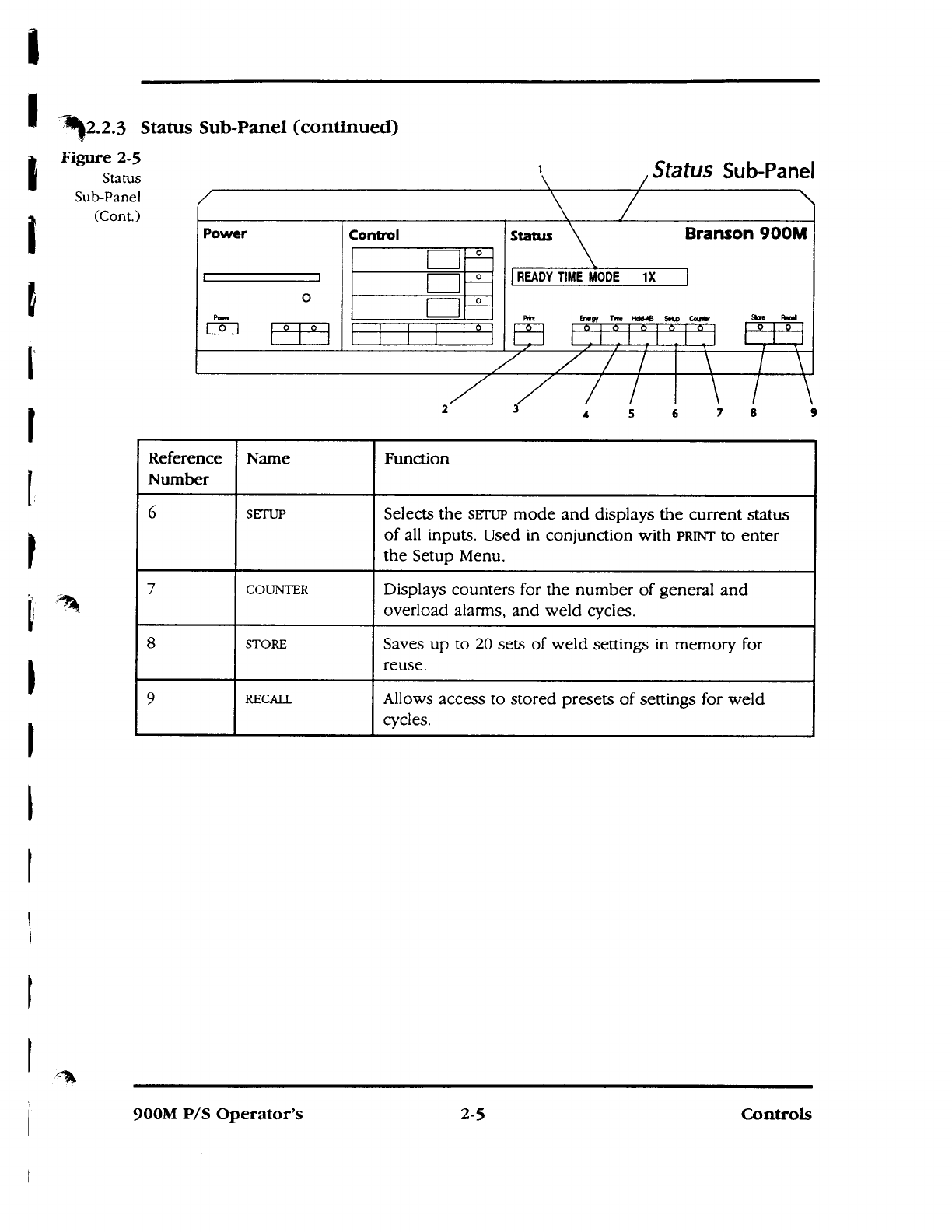
2.2.3 Status Sub-Panel (continued)
Figure 2-5
Status
Sub-Panel
(Cont.)
Power
O
Control
0
0
0
Status
Branson 900M
READY TIME MODE 1X
Status
Sub-Panel
Stae Fluel
I
Rnt
Enegy Trne Held-AB Selp Gamier
2
3
1
77
4 5 6 7 8 9
Reference
Number
Name
Function
6
SETUP
Selects the
SETUP
mode and displays the current status
of all inputs. Used in conjunction with
PRINT to
enter
the Setup Menu.
7
COUNTER
Displays counters for the number of general and
overload alarms, and weld cycles.
8
STORE
Saves up to 20 sets of weld settings in memory for
reuse.
9
RECALL
Allows access to stored presets of settings for weld
cycles.
0 I
O
900M P/S Operator's
2-5
Controls

5
10
a
i7
.18
is
.7
7S
C MINX
START 1 WIN L
TN LINK CLAM
DD
U
U
BRANSON
8
-
-0
0=
BRANSON
INYININO
2.3 Back Panel
Figure 2-6
Back
Panel
Reference
Number
Name
Function
1
Power Switch
Turns 900M On and Off.
2
Fuses (F1) and (F2)
Protects the 900M from damage if the AC main
power source fails. Fuse (F2) protects the 920M,
930M, and 905/910M 100-200/250V models only.
3
RF Connector (J1)
3-pin MS, for RF cable, provides ultrasonic energy
to the converter.
4
Line Cord
Connects 900M to AC power source.
5
External Power Signal
Connector Knockout (J8)
2-pin, provides an optional 0-5V interface for
power monitoring devices (refer to Appendix A).
6
Control Cable (J7)
15-pin D-shell, connects the 900M to an actuator or
stand.
7
START Cable (J6)
9-pin D-shell, connects 900M to external START/STOP
controls.
8
DATA LINK connectors (J4
and J5)
Provides connectivity for optional external
900AES/AOS or ECI-1.
9
ALARM connector (J3)
25-pin D-shell, provides input/output signals for an
external alarm interface.
10
EXTERNAL AMP. CONTROL
(J2)
7-pin, provides connectivity for optional EXTERNAL
OUTPUT CONTROL (Appendix A).
Controls
2-6
900M P/S Operator's

I
I
I
I
I
I
I
I
900M Series
Power Supplies
Installation

ontents of this Section
3.1 Introduction
3-1
3.2 Unpacking and Handing
3-1
3.3 Location
3-2
3.4 Power Requirements
3-2
AC
Power Connection
3-2
Setting Taps
3-3
3.5 Electrical Connections
3-6
RF
Connections
3-9
EXTERNAL START
Cable Connections
3-9
Input/Output Connections
3-11
Opto-Isolation Outputs
3-15
Suspect Weld Detection
3-15
Control Cable Signals
3-16
3.6 Branson Maintained Start Operating System
3-16
3.7 Automation Systems
3-17
Using Maintained Start MBOS
3-17
Choosing 24V Status Alarms or Contact Closures
3-18
Using
EMERGENCY STOP
as an Interlock
3-18
3.8 Assembling Converter, Booster and Horn
3-19
Assembling the Converter, Booster and Horn Stack
3-19
Connecting Tip to Horn
3-21
Disassembling Converter, Booster or Horn
3-22
Removing Tip from Horn
3-22
3.9 Converter Cooling
3-22
3.10DIP Switch 51
3-24
Setting
DIP Switch
Si
3-24
3.1 Introduction
This section describes how to install and set up a 900M together with a welding system. It
describes power connections, setting taps and how to connect the 900M to different
actuator configurations. These connections include non-automated, automated and
computer controlled connections. In addition, the section describes how to connect the
actuator stack (converter, booster and horn) and setting the
DIP
switch Sl.
3.2 Unpacking and Handling
1.
Unpack the 900M as soon as it arrives.
2.
Inspect the controls, indicators and surface for signs of damage.
3.
Open the cover of the 900M to check whether components became loose during
shipping. While the 900M's cover is removed, set the line transformer taps, described
in Section 3.4,
b. Setting Taps.
900M P/S Operator's
3-1
Installation

Note: If damage has occurred, notify the shipping company immediately. Retain
packing materials for inspection.
3.3
Location
1.
Install the 900M within 25 ft./7.5 m (15 ft./5.5 m for 40 kHz) of the converter and in
an area away from radiators or heating vents.
2.
Allow sufficient clearance to the back of the 900M to provide access to the connectors
(approx. 6 in/150 mm minimum).
3.
Observe the following:
•
Do not block exhaust and intake air circulation, which is needed to maintain a
safe operating temperature.
•
Operate the power supply only in an ambient temperature range of 41°F to 122°F
(5°C to 50°C).
If the power supply temperature reaches 185°F/85°C, a thermal switch will stop
ultrasonics and the power supply will display an Overload alarm. Ultrasonics remain
off until the unit cools to a safe operating temperature and you press RESET.
4. Check to see that dust or dirt does not restrict the flow of air exhaust, and clean the
air ports as necessary.
3.4 Power Requirements
A
Warning:
Be sure the power switch is in the Off position before making any electrical
connections.
To prevent the possibility of an electrical shock, always plug the 900M into a
grounded power source.
3.4.1 AC Power Connection
Plug the 900M into a single-phase, grounded, 3-wire, 50-60 Hz, 200-250 VAC power
source.
Figure 3-1
Plug and
Receptacle
Requirements
Model
Equipped with:
Needs:
905/910/943/947M 117V
NEMA 5-15P plug
NEMA 5-15R receptacle
920M
NEMA L6-20P plug
NEMA L6-20R receptacle
930M
NEMA L6-30P plug
NEMA L6-30R receptacle
k* Caution:
When connecting the line cord plug, make sure the shield is connected to
ground.
Installation
3-2
900M P/S Operator's

3.4.2
Setting Taps
If you have a 200-250V 900M, you may have to set the line transformer taps. These
models may also require other plugs, conforming to local codes.
The line transformers on units other than 117V models contain voltage selection taps
allowing you to match the 900M to your main
AC
voltage. Use the following procedure:
1.
Using a voltmeter, measure the main
AC
voltage at the receptacle and record the
value.
Warning:
Be sure the 900M is unplugged before removing the cover.
2.
Turn the 900M on its side and loosen the four captive retaining screws located on the
bottom of the 900M (Figure 3-2).
Figure 3-2
COVER RETAINIM SCREWS
Cover
Retaining
Screws
900M P/S Operator's
3-3
Installation
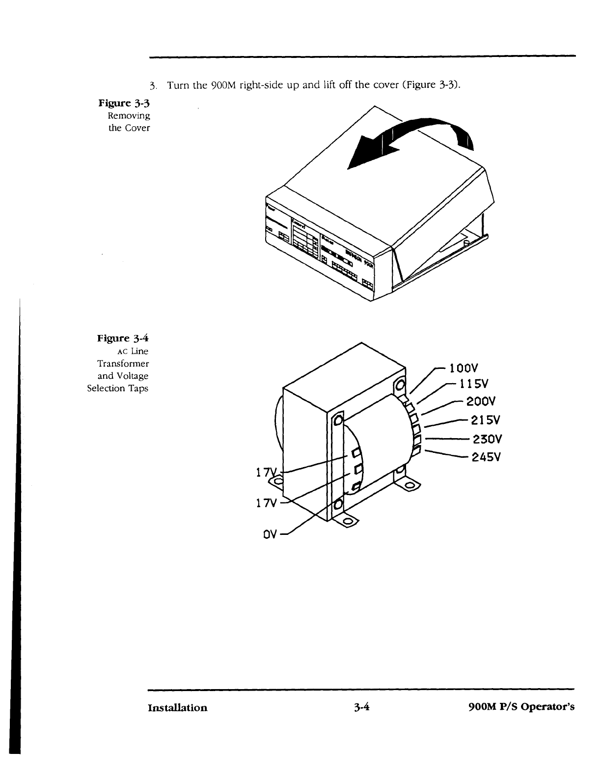
3. Turn the 900M right-side up and lift
off the cover (Figure 3-3).
Figure
3
-
3
Removing
the Cover
Figure 3-4
Ac Line
Transformer
and Voltage
Selection Taps
111
.000
1
115V
200V
100V
il°0
215V
0
245V
111PP
I
PEr
1
1
1
0
OV
1 7V
Installation
3-4
900M P/S Operator's
-4111
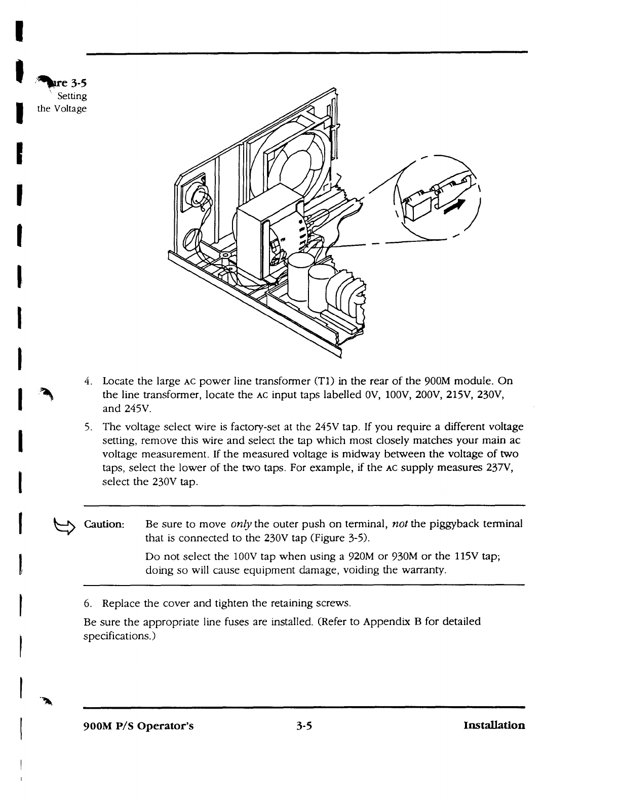
*.re 3-5
Setting
the Voltage
4.
Locate the large
AC
power line transformer (T1) in the rear of the 900M module. On
the line transformer, locate the
AC
input taps labelled OV, 100V, 200V, 215V, 230V,
and 245V.
5.
The voltage select wire is factory-set at the 245V tap. If you require a different voltage
setting, remove this wire and select the tap which most closely matches your main ac
voltage measurement. If the measured voltage is midway between the voltage of two
taps, select the lower of the two taps. For example, if the
AC
supply measures 237V,
select the 230V tap.
Caution:
Be sure to move
only
the outer push on terminal,
not
the piggyback terminal
that is connected to the 230V tap (Figure 3-5).
Do not select the 100V tap when using a 920M or 930M or the 115V tap;
doing so will cause equipment damage, voiding the warranty.
6.
Replace the cover and tighten the retaining screws.
Be sure the appropriate line fuses are installed. (Refer to Appendix B for detailed
specifications.)
900M
P/S
Operator's
3-5
Installation

Regulator/
gauges
Solenoid
valve 1
Line cord
900M P/S
Figure 3-6
900M-
900AE/AO
Actuator
Connections
RF
Data link
Accessory
interface
(board)
Data link
Alarm
Control
Start/stop
Power signal
Line cord
900AE/A0
Actuator
24V I/O
Module
'Customer controls
L - _
] J931
ECI
(optional)
3951
J971
J921
.7911
3.5
Electrical Connections
The following figures show electrical connections for non-automated, automated and
computer-controlled connections with 900AE/AO, 900AES/AOS and 94A0 Actuators.
Base
Note: 900A0/AOS Actuators use external pneumatic components. The solenoid valve
wires directly to the actuator.
Installation
3-6
900M P/S Operator's
900M Series
Power Supplies
100-214-163
Rev. D
MBOS Version 11/12
BRANSON Ultrasonics Corporation
41 Eagle Road
Danbury, CT 06813-1961
(203) 796-0400
Operator's Manual

Please read before servicing the 900M:
1.
Be sure the power switch is in the Off position before making any electrical
connections.
2.
To prevent the possibility of an electrical shock, always plug the 900M into
a grounded power source.
3.
Be sure the 900M is unplugged before removing the cover.
4.
A 900M powerdown or failure could adversely impact the automation
control box or the programmable controller.
5.
All automation systems working with 900M power supplies MUST use the
READY
state signal
6.
Be sure power is disconnected from the 900M before setting the
DIP
switch.
7.
High voltage is present in the 900M. Do not operate with the cover removed.
8.
Keep hands from under the horn. Down force (pressure) and ultrasonic
vibrations can cause injury.
9.
Large plastic parts may vibrate within the audible frequency range when
welded. If this occurs,
use
hearing protectors to prevent possible injury.
(See Appendix E, "Manufacturers of Hearing Protectors."
10.
Do not press the
TEST
key on the 900M or cycle the welding system if either
the RF cable or converter is disconnected.
11.
Do not contact the horn when you press
TEST.
12.
When using larger horns, avoid situations where fingers could be pinched
between the horn and the fixture.
900M P/S Operator's
iii
Warnings

Limited Warranty
Each standard 900 Series ultrasonic product manufactured by Branson used in
rigid
plastic joining
applications is guaranteed in the United States and Canada to be free
from defects in workmanship and material for thirty six (36) months from the date of
invoice. The guarantee of 900 Series products used in other applications (for example
textiles) is limited to twelve (12) months from date of invoice.
The warranty does not apply to any product which has been subjected to misuse,
misapplication, neglect (including without limitation, inadequate maintenance, proper
ventilation or cooling), accident, or improper installation, modification, adjustment or
repair, or use with an improperly tuned horn.
Products supplied by Seller, but manufactured by others are warranted only to the extent
of the manufacturer's warranty. The guarantee period for certain product lines will be
extended at the discretion of Branson. If rented equipment is converted to purchase,
guarantee period commences at date of original rental shipment and not from date of
conversion.
Disclaimer of Warranty
The foregoing warranty constitutes Seller's only warranty in connection with any sale, and
is in lieu of all other warranties expressed or implied, written or oral: THERE ARE NO
IMPLIED WARRANTIES OF MERCHANTABILITY OR FITNESS OF ANY PRODUCT FOR A
PARTICULAR PURPOSE.
Exclusive Remedy
SELLER'S LIABILITY SHALL BE LIMITED TO REPAIRING OR REPLACING THE PRODUCT
FOUND BY SELLER TO BE DEFECTIVE OR NON-CONFORMING, OR, AT SELLER'S
OPTION, TO REFUNDING THE PURCHASE PRICE OF SUCH PRODUCT. At Seller's
request, Buyer shall send, at Buyer's expense, any allegedly defective product to the
factory where it was manufactured. The remedy set forth above is exclusive.
The repair or replacement of the product, or refund of the purchase price, constitutes
fulfillment of all liabilities of Seller to Buyer under the warranties above-mentioned,
whether based on contract, negligence of any kind, strict liability or tort, or otherwise
with respect to or arising out of product furnished under the sales contract.
Branson Ultrasonics Corp.
Warranty
Limitation of Liability
Buyer expressly agrees that, notwithstanding any other provision of this contract, under
no circumstances shall Seller's total aggregate liability resulting from:
1.
The performance, failure to perform or breach of Seller's obligations; and
2.
Any activity undertaken by Seller with regard to equipment and services covered by
the sales contract; and
3.
All actions based on negligence of any kind, strict liability or tort on the part of Seller
or its suppliers; and
4.
Otherwise, exceed the price paid by the Buyer for the product. BUYER EXPRESSLY
AGREES THAT SELLER WILL NOT BE LIABLE UNDER ANY THEORY OF LIABILITY
FOR ANY DIRECT, SPECIAL, INCIDENTAL OR CONSEQUENTIAL DAMAGES,
INCLUDING, WITHOUT LIMITATION, THE LOSS OF USE, INCOME, PROFITS OR
PRODUCTION; OR INCREASED COST OF OPERATION; OR DAMAGE TO MATERIAL,
ARISING IN CONNECTION WITH THE SALE, INSTALLATION, USE OF, INABILITY TO
USE, OR REPAIR OR REPLACEMENT OF SELLER'S PRODUCTS.
Buyer shall indemnify and hold Seller harmless for any liability to Buyer's employees,
workers, contractors or any other persons beyond the limitation provided in this
section.
Limitation on Claims and Actions
Any claim by Buyer for breach of the foregoing warranty shall be deemed waived by
Buyer unless submitted to Seller in writing within thirty (30) days from the date Buyer
discovered or by reasonable inspection should have discovered the alleged breach. Any
cause of action for breach of the foregoing warranty shall be brought within one year
after the cause of action has accrued.
vi
Branson Ultrasonics Corp.
Warranty

900M Series
Power Supplies
Table of Contents

Section
Page
New Features
xiii
1.
Introduction
1.1 Introduction
1-1
1.2 900M Overview
1-1
1.3 900M Features
1-2
1.4 Inputs
1-3
1.5 Welding Systems
1-3
1.6 Further References
14
2.
Controls
2.1 Introduction
2-1
2.2 900M Front Panel
2-1
2.3 900M Back Panel
2-6
3.
Installation
3.1 Introduction
3-1
3.2 Unpacking and Handing
3-1
3.3 Location
3-2
3.4 Power Requirements
3-2
3.5 Electrical Connections
3-6
3.6 Branson Maintained Start Operating System
3-16
3.7 Automation Systems
3-17
3.8 Assembling Converter, Booster and Horn
3-19
3.9 Converter Cooling
3-22
3.10
DIP
Switch 51
3-24
4.
Operation
4.1 Introduction
4-2
4.2 Weld Modes
4-4
4.3 Weld Mode Settings
4-6
4.4 Weld System Settings
4-27
4.5 Making a Weld Cycle
4-51
4.6 Other Functions
4-62
900M P/S Operator's
vii
Table of Contents
This manual suits for next models
6
Table of contents
Other Branson Power Supply manuals


