Brantz International 3 Pro User manual
Set Up & Operating Instructions for
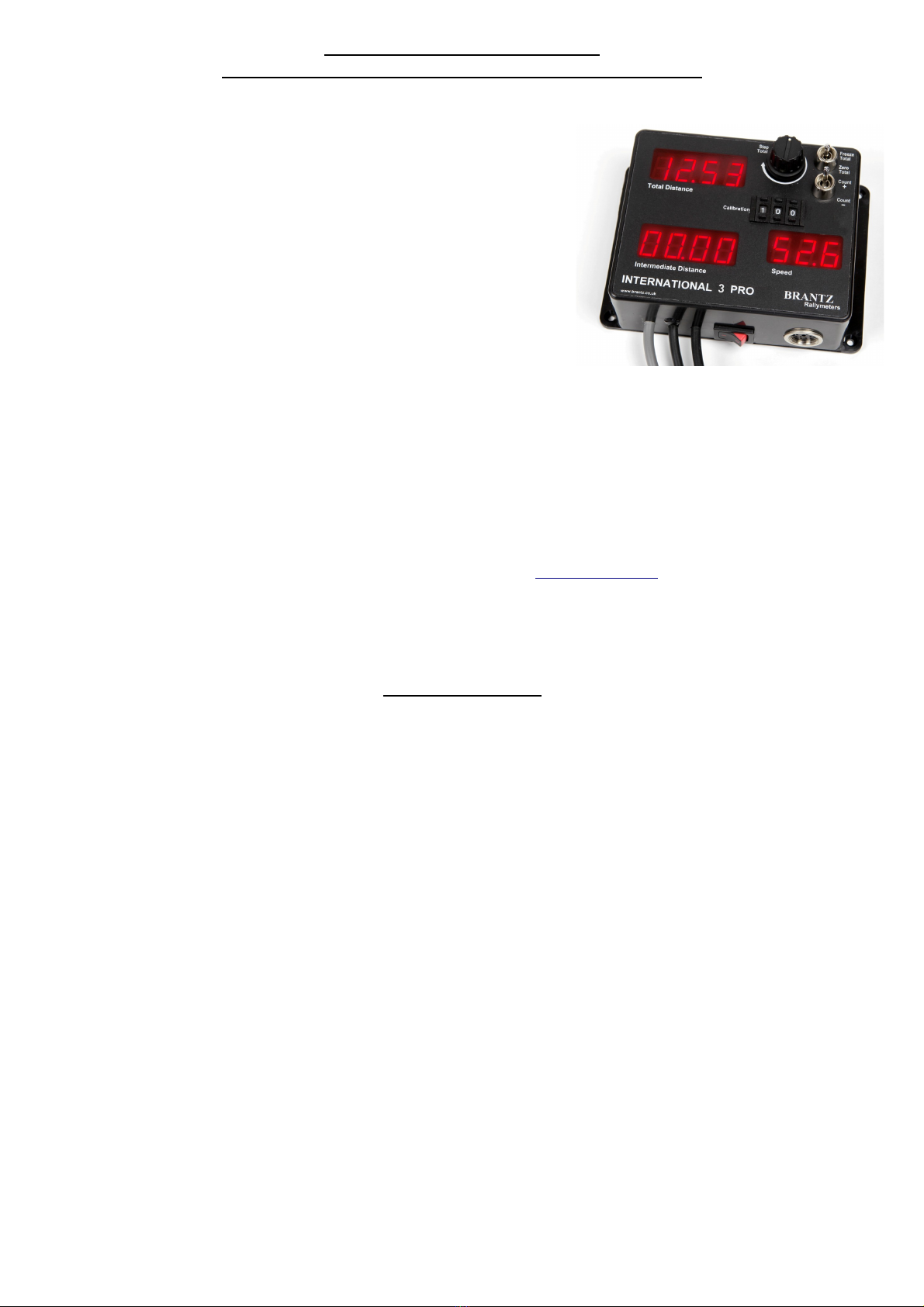
Brantz International 3 Pro + Driver Display Tripmeter (B 8-DD)
Wiring (Not Applicable of you are using your meter in conjunction with a B 57 & B 45/B 47):
•Power:
•Connect up to the vehicles 12 volt power supply as directed by the label
on the BLACK POWER CABLE co ing out of the base of the trip eter or
Plug Kit (BR43). This is BROWN to the POSITIVE Ter inal and
GREEN/YELLOW to the NEGATIVE Ter inal.
•Connect straight to the vehicles battery posts via a 2 Amp fuse (Not
Provided - Available fro Brantz) on the live wire, usually the BROWN
on +12V cars, however on Positive Earth vehicles it is custo ary to fit
the fuse to the live GREEN/YELLOW wire.
•Sensor:
•The Sensor is connected to the GREY CABLE co ing out of the base of
the trip eter as directed by the separate sensor instruction sheet
showing how to wire the exact type of sensor you have chosen.
Calibration:
•The Trip eter is calibrated to be accurate on any vehicle fitted with any type of Brantz Sensor and using any wheel size or
gearing by eans of the three push-wheel switches arked 'CALIBRATION'.
•If the Trip eter is to easure in hundredths of a Kilo etre/Mile the push-wheel switch needs first to be set to 100.
•At the start of an accurately easured Kilo etre/Mile, press the Zero button to ensure the counter reads 00.00.
•Drive the easured distance and stop accurately at the end of the distance – Note the figure that co es up on the readout.
(This is the Calibration Figure for this particular vehicle)
•Enter this figure into the calibration push-wheel switches on the front of the trip eter. e.g. If the readout is 05.67 set the
push-wheel switches to 567. N.B. If the readout is greater than 09.99 a Pre-Scaling Interface (B 5)/Dividing Pre-Scaler (B 5-
2A) is required – please contact us on 0044 (0) 1625 669366 or E ail: sales@brantz.co.uk
•The accuracy can be confir ed by re-running the easured distance after zeroing the readout, the eter should read exactly
01.00
•If several wheel sizes and gearings are available for the vehicle; repeat the calibration procedure for each co bination and
note down the different calibration figures.
Operating Instructions
Use/Controls:
•The trip eter is switched on by use of the rocker switch on the base of the trip eter.
•When the switch is oved fro position '0' to the 'I' position the eters digits will light up. N.B. A battery charger is not a
suitable power source to test the trip eter.
•The ED button on the re ote reset box, when pressed will zero the INTERMEDIATE DISTANCE readout.
•The upper toggle switch on the front of the trip eter arked 'Freeze Total'/'Zero Total' has 3 positions and will nor ally be
in the iddle position.
•If the switch is pushed UP the TOTAL DISTANCE readout will be FROZEN, when the switch is returned back to the
iddle position the readout out will continue fro the Frozen value. (This facility is useful if the competitor wishes
to correct (Pre-Set) the Total Distance readout to a value that he knows should be displayed at a certain point on the
road. The readout can be unfrozen at this point on the road so that the correct value is displayed from this point on.
This facility is also useful if the Total Distance readout is too hi h; the readout can be frozen and then the vehicle
driven without the displayed value increasin ).
•If the switch is o entarily switched DOWN this will Zero the TOTAL Readout.
•The lower toggle switch on the front of the trip eter arked 'Count +'/'Count –' allows the trip eter to count upwards or
downwards.
•The STEP control knob is to edit the TOTAL DISTANCE readout value. Turning the knob clockwise a click will be felt and the
TOTAL DISTANCE readout will start to count either up or down depending on the position of the Count +/Count – toggle
switch. (This facility is useful to ali n the Total readout value to any iven value , say, by the or anisers handbook at a certain
point).
•The STEP control can be used with the FREEZE switched ON.
•The STEP control should nor ally be in the off position that is turned fully anti-clockwise until a click is felt.
•The three digit 'SPEED' readout will display the vehicles current speed to one deci al place in the units to which the
trip eter is calibrated i.e. calibrated in iles, shows ph or calibrated in kilo etres shows kph.
•This trip eter will NOT show Average Speed.
•For Long Distance Events the deci al place can be shifted fro 00.00 to 000.0, by the following ethod:
•With the trip eter OFF; hold down the Zero Total toggle switch and switch the trip eter ON.
•The trip eter will return to it's default 00.00 when the unit is switched Off and On again
•Driver Display Tripmeter Facilities (B 8-DD):
•The circular Socket on the botto of the trip eters for the Driver display unit to attached – Please ensure you screw
the corresponding plug into the socket as this creates the earth connection.
•The RED button on the top of the Trip eter allows the Co-Driver to scroll through the displays that the driver will
see on his Driver Display Unit (BR71): Total Distance : Intermediate Distance : Speed
•The driver will see an exact replica of the displays on the trip eter.
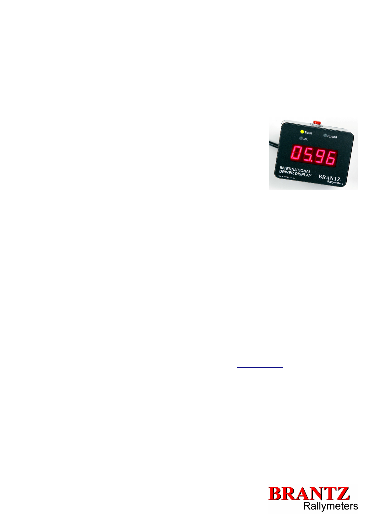
•International Driver Display facilities (B 81):
•The RED button on the top of the Driver Display Unit allows the Driver to scroll
through the displays that the driver will see on his Driver Display Unit (BR71-
NAS): Total Distance : Intermediate Distance : Speed
•A Green LED will light up above the display to indicate which display you are
currently viewing.
•The Rocker Switch on the back of the Driver Display Unit has 3 positions:
•ON – OFF – DIM
•The Di setting reduces the brightness of the displays for night ti e driving
so as not to glare the driver.
Official Measured Distances and Calibration
If the rally organiser has laid out an 'official distance' or you wish to make your tripmeter read the same as the rally organisers
distances then the following instructions apply for calibration:
•Enter 100 (C) into the push-wheel calibration digits (N.B. If the official easured distance is greater than 20 iles you would
need to enter a uch higher figure for C e.g. between 399-999).
•With the Total and Inter ediate Displays showing Zero drive the total official easured distance i.e. 4.8 (D) iles and note
down the readings i.e. 21.98 (T) (this should be identical on both Inter ediate and Total Displays)
•Now use the following for ula:
(T/D) x C
e.g.
(21.98/4.8) x 100
=>4.579 x 100
=>457.91
So enter 458 into your calibration push-wheel switches.
To confir the figure, re-drive the easured distance and your displays should show the official distance e.g. 4.8 iles.
Trouble-Shooting:
•If you are having proble s please see our Trouble-Shooting guide available at www.brantz.co.uk, contact your supplier or
Phone us on: 0044 (0) 1625 669366
v1.1
Table of contents
Other Brantz Measuring Instrument manuals


Popular Measuring Instrument manuals by other brands


sauter
sauter TN-EE instruction manual

Agilent Technologies
Agilent Technologies E5500A user guide

Perfect Prime
Perfect Prime CO2512 instruction manual

Craftsman
Craftsman CMHT77637 user manual

Keysight Technologies
Keysight Technologies EPM-P Series Programming guide

Major tech
Major tech MT155 instruction manual


