Brasch BH-P-961 Series User manual

REV. LEVEL ECO 1-7521 03/2019 FORM 8208 1 OF 5
BH-P-961 SERIES
CONFINED SPACE
UNIT HEATER
Horizontal or Vertical Mounting
ATTENTION:
Read carefully before attempting
to install or operate Unit Heater
.
FEATURES:
• Forced air electric unit heater available in:
240/208 volt single phase, 5 kw and 240 and
480 three phase 5 kw.
• 240/208 single phase unit is factory wired for
5 kw. The wattage may be changed by moving
jumpers as indicated in table 1.
• 24 volt control standard on three phase unit.
• All units with “T” sufx provided with unit
mounted hydraulic thermostat.
• Mounting bracket included with all units.
PROPER MOUNTING:
The heater(s) should be located along outside
walls or other areas of greatest heat loss.
Multiple heaters should be spaced to set up a
gen
erally
circular air movement, each heater
supporting the air stream of the other.
IMPORTANT: OWNER SHOULD RETAIN THESE INSTRUCTIONS FOR FUTURE REFERENCE
EXPOSED
EXPOSED
H
H
H
H
H
EXPOSED
EXPOSED
REV. LEVEL ECO 1-7521 03/2019 FORM 8208 2 OF 5
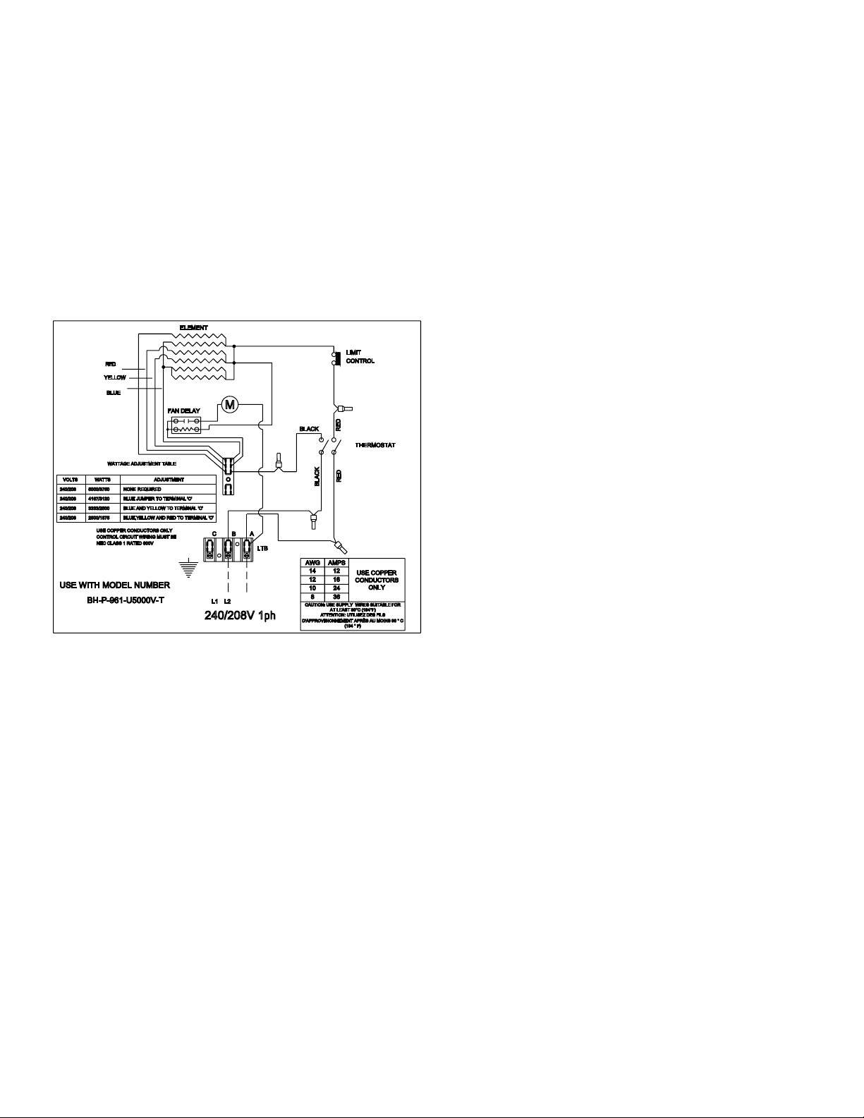
PRINCIPLES OF OPERATION
When the thermostat calls for heat, the elements
are immediately energized, a fan delay brings
on the fan after the elements are heated allow
ing
warm air to circulate. When the thermostat is
satised, the elements are de-energized and the
fan purges the heater of residual heat.
The heater wattage may be eld adjusted only on
model BH-P961-U5000V-T.
Select the desired
wattage from Fig. 1 and move color coded
jumpers as indicated.
Fig.1
INSTALLATION INSTRUCTIONS
All electric unit heaters are shipped fully
assembled. Installation includes hanging the
unit and electrical wiring to the unit.
The wall and/or ceiling structure must be
sufcient to support the combined weight of
the heater and any mounting bracket and
accessories.
Be sure power source is de-energized before
installing heater. Check heater voltage and
phase listed on heater data label on
back of unit to make sure they are the
same as the electrical service supplied.
MOUNTING THE HEATER
Select the mounting location. Be sure to observe
the minimum mounting clearances as shown in
Figure 2.
The heater can be mounted either from the
ceiling or wall depending on the application.
The mounting bracket is supplied with 3/8” holes,
10 inches on center for threaded rod mounting or
direct mounting to the structure.
The heater cabinet also has 3/8” weld nuts 10” on
center to allow threaded rod mounting without the
bracket.
1. Install the mounting bracket in the desired
location
with threaded rod or hardware that is
appropriate for the mounting surface. If using
threaded rod, two nuts, one on the top and
one on the bottom of the bracket along with a
split washer is suggested.
2. Secure the heater to mounting bracket, using
the 1/4-20 x 3/4” machine screws and lock-
washers provided.
3. Position the heater, aligning the bracket holes
with the cabinet holes and secure bracket
to the cabinet with the 1/4-20 x 1/2” machine
screws and nuts that are provided. With the
mounting bracket in the vertical position the
1/4” nuts are not necessary, weld nuts are
supplied in the cabinet.
RED
BLACK
RED
BLACK
AWG AMPS
USE COPPER
CONDUCTORS
ONLY
14 12
12 16
10 24
8 36
CAUTION: USE SUPPLY WIRES SUITABLE FOR
AT LEAST 90°C (194°F)
ATTENTION: UTILISEZ DES FILS
D'APPROVISIONNEMENT APRÈS AU MOINS 90 ° C
(194 ° F)
A
B
C
USE WITH MODEL NUMBER
BH-P-961-U5000V-T L2L1
LTB
240/208V 1ph
USE COPPER CONDUCTORS ONLY
CONTROL CIRCUIT WIRING MUST BE
NEC CLASS 1 RATED 600V
VOLTS
240/208
240/208
240/208
240/208
WATTAGE ADJUSTMENT TABLE
ADJUSTMENT
NONE REQUIRED
BLUE JUMPER TO TERMINAL 'C'
BLUE AND YELLOW TO TERMINAL 'C'
BLUE,YELLOW AND RED TO TERMINAL 'C'
5000/3750
4167/3120
3333/2500
2500/1875
WATTS
ELEMENT
THERMOSTAT
CONTROL
LIMIT
FAN DELAYM
REV. LEVEL ECO 1-7521 03/2019 FORM 8208 3 OF 5
Fig. 2
POWER CONNECTION
To avoid possible electrical shock, be sure the electrical current is turned off at the main switch
prior to wiring or servicing of unit.
1.
Remove the access panel, by removing four screws, two on the front and two on the back
.
2. Remove desired knockout on side or back of the heater.
3.
Following the correct unit wiring diagram, connect the power supply and electrical ground to the
correct terminals using accepted practices recognized by local codes. See Table 1 for minimum
circuit requirements.
4.
Replace the access panel, tighten the screws to ensure a good seal to help prevent dust and dirt
from entering the control compartment.
0"
24"
MINIMUM
DISTANCE
FROM
FRONT
TO ANY
OBJECT
MINIMUM INSTALLATION CLEARANCES:
SIDES, TOP AND BOTTOM 0 INCHES
REAR: 8 INCHES (203mm)
FRONT: 24 INCHES (610mm)
Dégagements minimums MONTAGE:
Côtés, le haut et le bas 0 pouces
ARRIÈRE: 8 pouces (203mm)
AVANT: 24 pouces (610mm)
14.4
14.6
5.1
8.0"
MIN. TO WALL
10.0
W
A
L
L
FLOOR
0"

REV. LEVEL ECO 1-7521 03/2019 FORM 8208 4 OF 5
Note: Supply wire must be 90°C AWG minimum.
OPERATION
1. Restore power to the unit.
2. Turn the thermostat up to energize the unit. When the area reaches the desired temperature, rotate
the thermostat knob counter- clockwise slowly until the heat turns off.
3. This 961 series is provided with a fan delay/purge. When the heater is turned on, the
ele
ments willheat up before the fan comes on (approx. 30 seconds). This allows for warm
air circulation. When the thermostat is satised, the elements will de-energize and the fan
will continue to run (approx. 30 seconds) allowing residual heat to be purged from the heater.
4. The 961 abnormal situation such as fan failure or other over-temp. situations the limit control will
cycle the heater off. In the event of an over-temp situation, the heater should be inspected to
determine the cause and repaired by authorized personnel.
GENERAL SAFETY INFORMATION:
CAUTION:
Follow all local electrical and safety codes, as well as the National Electric Code (NEC) and the
Occupational Safety and Health Act (OSHA).
To avoid possible electrical shock, be sure the electrical current is turned off at the main switch prior to
wiring or servicing of unit.
If the power disconnect is not integral and is out-of-sight, lock it in the open position and tag to prevent
unexpected application of power prior to performing any service of maintenance on the unit.
The unit when installed must be electrically grounded in accordance with the National Electrical Code
and standard industry practice.
Make certain that the power source conforms to the requirements of your equipment. See Table 1 for
information as to wire and circuit size.
Check heater voltage and phase on rating label to conrm it is the same as the electric service supply.
Wiring diagrams of the heaters and supply connections are permanently attached to the heater
access door. All terminals are coded in accordance with the wiring diagram.
The wall/ceiling mounting structure and anchoring provisions must be of sufcient strength to support
the combined weight of the heater and mounting bracket.
TECHNICAL DATA TABLE 1
MODEL VOLTS WATTS PHASE AMPS SUPPLY WIRE
BH-P-961-U5000V-T 240/208 5000/3750 1 20.83 / 18 10
BH-P-961-U5000K-T 240/208 5000/3750 3 12.04 / 10.4 12
BH-P-961-U5000U-T 480 5000 3 6.1 14

REV. LEVEL ECO 1-7521 03/2019 FORM 8208 5 OF 5
MAINTENANCE:
Caution: Make certain that the power source is disconnected before attempting to service or disassemble
any component. If the power disconnect is out of the line of sight, lock it in the OPEN position and tag to
prevent the application of power.
Electrical:
Once a year inspect the control panel wiring to make certain insulation is intact and all connections both
factory and eld are tight. Inspect all heater and relay contacts. If the contacts appear badly pitted or
burned, replace the contactor/relay.
Cleaning:
Clean the unit casing, fan and motor once a year. A dirty motor will tend to run hot and eventually will
be damaged internally. Any rust spots on the casing should be cleaned and repainted. The element
can be cleaned by removing the outer cabinet. Do not use any liquid to clean electric components.
Lubrication:
All units have fan motors that are permanently lubricated. No oiling is required.
425 Hanley Industrial Court St. Louis, Missouri 63144
1-888-731-7010
WIRING DIAGRAMS
BH-P-961-U5000K-T BH-P-961-U5000U-T
L3L2L1
LTB
CONTACTOR
COIL
CTB
LIMIT CONTROL
DELAY
FAN
CONTROL TRANSFORMER
ELEMENT
T-STAT
240V 3ph
AWGA MPS
USE COPPER
CONDUCTORS
ONLY
14 12
12 16
10 24
83 6
CAUTION: USE SUPPLY WIRES SUITABLE FOR
AT LEAST 90°C (194°F)
ATTENTION: UTILISEZ DES FILS
D'APPROVISIONNEMENT APRÈS AU MOINS 90 ° C
(194 ° F)
LTB
CAUTION: USE SUPPLY WIRES SUITABLE FOR
AT LEAST 90°C (194°F)
ATTENTION: UTILISEZ DES FILS
D'APPROVISIONNEMENT APRÈS AU MOINS 90 ° C
(194 ° F)
368
2410
1612
1214 USE COPPER
CONDUCTORS
ONLY
AMPSAWG
480V 3
p
h
CONTACTOR
COIL
CTB
FAN
DELAY
LIMIT CONTROL
CONTROL TRANSFORMER
L3L2L1
ELEMENT
THERMOSTA
T
M
This manual suits for next models
3
Table of contents
Other Brasch Heater manuals

Popular Heater manuals by other brands

Xvent
Xvent Breeze BR-15 Operating and installation instructions

Black & Decker
Black & Decker BDTH600 Use and care book

SEELEY INTERNATIONAL
SEELEY INTERNATIONAL Braemar Invertair SACV10D1S installation manual

Kenmore
Kenmore 408.91200310 Use & care guide

HIRED-HAND
HIRED-HAND Maywick SUPER-SAVER XL owner's manual

Soleus Air
Soleus Air MS-14R owner's manual


