Xvent Breeze BR-15 User manual

1
Version 1
–
GBR
(11/0
5
/2022)
D
-
502
-
02
60
OPERATING AND INSTALLATION INSTRUCTIONS FOR
THE COMMERCIAL BREEZE AIR CURTAIN

2
Version 1
–
GBR
(11/0
5
/2022)
D
-
502
-
02
60
TABLE OF CONTENTS
1. General information .................................................................................................................................................................. 5
1.1. Introduction ...................................................................................................................................................... 5
1.2. Warnings and Symbols ..................................................................................................................................... 5
1.3. Using the curtain .............................................................................................................................................. 6
1.4. Transport, Delivery Control, and Storage ........................................................................................................ 6
1.4.1. Transport ...................................................................................................................................................... 6
1.4.2. Delivery Inspection ....................................................................................................................................... 6
1.4.3. Storage .......................................................................................................................................................... 6
1.5. Contents of the Package .................................................................................................................................. 6
1.6. Before Commencing the Installation ............................................................................................................... 7
2. Technical parameters................................................................................................................................................................. 7
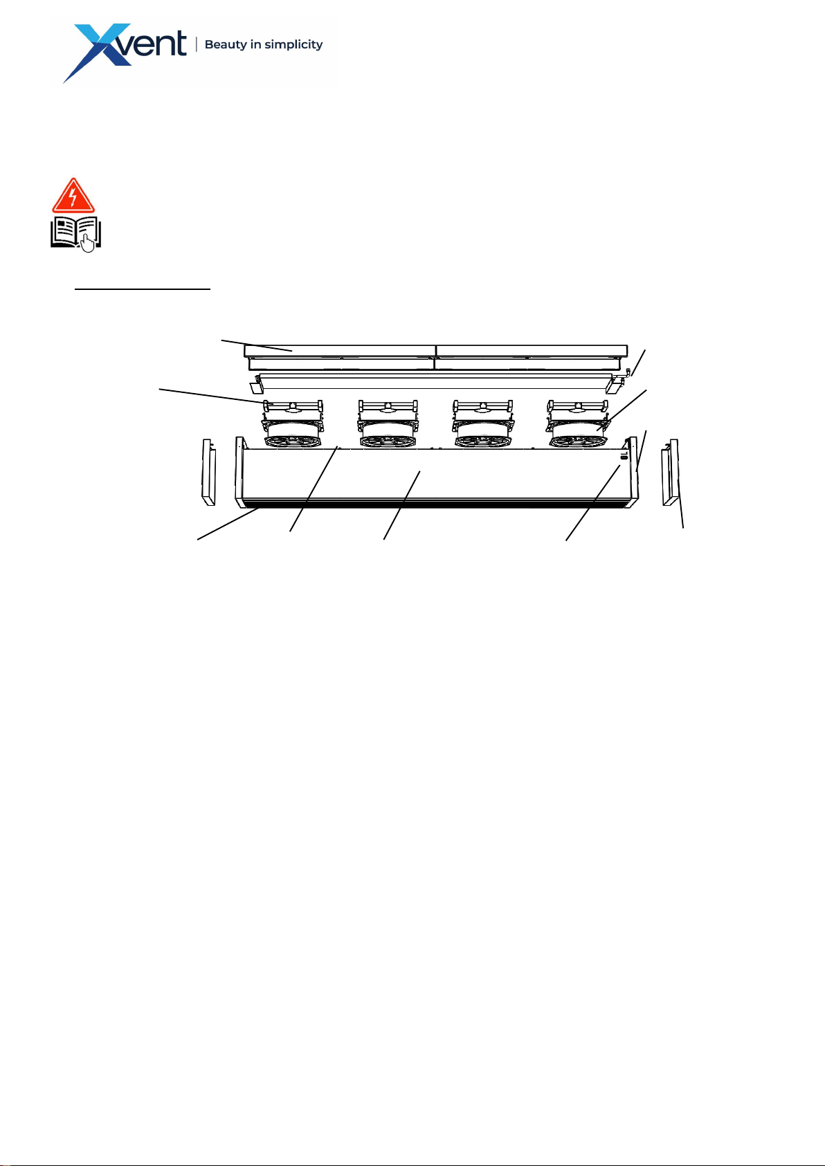
2.1. Breeze air curtain design .................................................................................................................................. 7
2.1.1. AC axial fan ................................................................................................................................................... 7
2.1.2. Water heat exchanger - BR1-xx-ACV1S-xxx ................................................................................................... 7
2.1.3. Electric bodies – BR1-xx-ACE1S-xxx ............................................................................................................... 7
2.1.4. Curtain shroud .............................................................................................................................................. 7
2.1.5. Curtain sidewall / regulation cover ............................................................................................................... 7
2.1.6. Intake cover / filter ....................................................................................................................................... 7
2.1.7. Exhaust vanes ............................................................................................................................................... 8
2.1.8. Regulation ..................................................................................................................................................... 8
2.1.9. Main switch................................................................................................................................................... 8
2.1.10. M6x20 bolts .................................................................................................................................................. 8
2.2. Main dimensions and minimum working space requirements of the Breeze air curtain ............................. 9
2.3. Technical parameters of Breeze air curtains ................................................................................................... 9
2.3.1. BREEZE-15 ..................................................................................................................................................... 9
2.3.2. BREEZE-20 ..................................................................................................................................................... 9
2.3.3. BREEZE-25 ................................................................................................................................................... 10
2.4. Technical data of water exchangers .............................................................................................................. 10
2.4.1. BR1-15-ACV1S-xxx ....................................................................................................................................... 10
2.4.2. BR1-20-ACV1S-xxx ....................................................................................................................................... 11
2.4.3. BR1-25-ACV1S-xxx ....................................................................................................................................... 11
3. Unit Installation ....................................................................................................................................................................... 11
3.1. General information, recommendations and safety before and during installation of the Breeze air curtain.......... 11
3.1.1. Electrical safety before installation of the curtain ....................................................................................... 11
3.1.2. Modification of heating distribution system ............................................................................................... 12
3.1.3. Load capacity of the installation site ........................................................................................................... 12
3.1.4. Minimum mounting clearances ................................................................................................................... 12
3.1.5. Minimum safety distances from combustible substances ........................................................................... 12
3.1.6. Curtain operating environment ................................................................................................................... 12

3
Version 1
–
GBR
(11/0
5
/2022)
D
-
502
-
02
60
3.1.7. Curtain alignment ....................................................................................................................................... 12
3.1.8. Unpacking the curtain - preparation before installation .............................................................................. 12
3.2. Vertical installation ........................................................................................................................................ 13
3.2.1. Fixing the curtain base to the floor .............................................................................................................. 13
3.2.1.2. Bottom curtain connection - from the floor - base (curtain regulation at the bottom - at the floor)............ 14
3.2.2. Placing the curtain in the working position ................................................................................................. 14
3.3. Vertical installation - chained curtains .......................................................................................................... 16
3.3.1. Installation of chained curtains ................................................................................................................... 16
3.4. Side anchoring of the chained assembly ....................................................................................................... 18
3.5. Vertical installation - increasing the shielding effect .................................................................................... 18
3.6. Horizontal installation .................................................................................................................................... 19
3.6.1. Selecting the installation location ............................................................................................................... 19
3.6.2. Auxiliary anchoring structures ..................................................................................................................... 19
3.6.3. Installation of the curtain in a horizontal position ....................................................................................... 19
3.6.4. Examples of hanging the curtain - horizontal installation ............................................................................ 20
3.6.5. Mounting-hanging the curtain in the working position ............................................................................... 20
3.7. Horizontal installation - chaining of curtains ................................................................................................ 21
3.7.1. Preparation of curtains before chaining ...................................................................................................... 22
3.7.2. Installation of chained curtains ................................................................................................................... 23
3.8. Water-type heat exchanger connection ........................................................................................................ 23
3.8.1. Connection of the curtain to the building hot-water distribution system .................................................... 23
3.8.2. Water-type heat exchanger connection ...................................................................................................... 23
3.8.3. Exchanger venting ....................................................................................................................................... 23
3.9. Wiring and electrical installation ................................................................................................................... 24
3.9.1. General Information – Safety ...................................................................................................................... 24
3.9.2. Power connection and curtain control ........................................................................................................ 24
3.9.3. Wiring and description of power and control terminals .............................................................................. 25
3.9.3.1. Wiring description of 1 curtain - electric version (BR-xx-ACE1-xxx) ............................................................. 25
3.9.3.2. Wiring description of 1 curtain - water version (BR-xx-ACV1-xxx) ............................................................... 25
3.9.3.3. Wiring description of 1 curtain - unheated version (BR-xx-ACS1-xxx) .......................................................... 26
3.9.3.4. Connecting curtains intended for chaining .................................................................................................. 26
3.9.4. Mains connection ........................................................................................................................................ 26
3.10. Electrical parameters shown on the curtain ............................................................................................. 27
4. Regulation ................................................................................................................................................................................ 27
4.1. General Information – Safety......................................................................................................................... 27
4.2. Description of regulation ............................................................................................................................... 27
4.2.1. Power control terminals .............................................................................................................................. 28
4.2.2. receiver of the signal from the wireless room thermostat: ......................................................................... 28
4.2.3. Wireless room thermostat .......................................................................................................................... 28
4.2.4. Pairing multiple curtains with a single wireless thermostat ........................................................................ 28

4
Version 1
–
GBR
(11/0
5
/2022)
D
-
502
-
02
60
4.2.5. Curtain switch-off delay device ................................................................................................................... 28
4.2.6. Magnetic door contact ................................................................................................................................ 28
4.2.7. Technical parameters of the regulation accessory - part of standard delivery of the curtain ....................... 29
4.2.8. Description of regulation settings ............................................................................................................... 29
4.2.8.1. Setting the curtain performance according to the size - height of the shielded opening ............................. 29
4.2.8.2. Setting of delayed curtain switching-off ...................................................................................................... 29
4.2.9. Description of regulation logic .................................................................................................................... 30
4.2.10. Factory regulation setting ........................................................................................................................... 30
4.3. Technical parameters of regulation accessories - external elements .......................................................... 30
5. Wiring diagram of the Breeze curtain ..................................................................................................................................... 31
5.1. Electric version - BR1-xx-ACE1S-xxx ............................................................................................................... 31
5.2. Water version - BR1-xx-ACV1S-xxx ................................................................................................................ 32
5.3. Unheated version - BR1-xx-ACS0S-xxx .......................................................................................................... 33
5.4. Example of chained curtains wiring ............................................................................................................... 34
6. Commissioning ......................................................................................................................................................................... 35
6.1. Prior to first startup, check the following: .................................................................................................... 35
6.2. Switching on ................................................................................................................................................... 35
7. Regular maintenance ............................................................................................................................................................... 35
7.1. Regular maintenance ..................................................................................................................................... 35
7.2. Curtain cleaning procedure ............................................................................................................................ 35
8. Servicing ................................................................................................................................................................................... 38
8.1. Troubleshooting procedure ........................................................................................................................... 38
8.2. Failure persists ................................................................................................................................................ 38
9. Final Decommissioning, Dismantling, and Disposal................................................................................................................ 39
10. Warranty ............................................................................................................................................................................. 39
11. In Conclusion ....................................................................................................................................................................... 40

5
Version 1
–
GBR
(11/0
5
/2022)
D
-
502
-
02
60
1. General information
1.1. Introduction
- This "Installation and Operating Instructions" document is for the Breeze Air Curtain (hereafter referred
to as
Curtain, product), which is used to separate the internal and external environment by air flow and hot air
heating of the required space.
- Detailed familiarisation with this document is important for the correct and safe installation and
functioning of the curtain. Failure to comply with the conditions in this document may result in
malfunction of the curtain or damage to property and health.
- The installation and connection of the curtain must only be carried out by a trained person with the
appropriate authorisation for
wiring electrical equipment, having the appropriate tools and resources available. During assembly,
all the instructions and recommendations provided in this manual must be observed.
- For proper operation and long life of the curtain, it is necessary to prevent access of unauthorized persons
and
train the operator in accordance with this document and relevant legislation.
- Documentation and instructions must always be available at the installation site, keep it for future use.
- It is forbidden to interfere in any way with the curtain internal connection other than as specified in this
manual. Due to the continuous development of our products, we reserve the right to change this manual
without prior notice.
- The curtain may only be operated by trained persons over 18 years of age with adequate physical, sensory
and mental abilities who understand how to use the curtain in a safe manner and understand the
potential hazards.
1.2. Warnings and Symbols
- The following names and symbols shall be used in the operating manual, on the packaging, and on the
product for particularly important information:
Caution - Danger warning
Caution - Risk of electrical shock
Protective conductor connection
Reference to another manual section
Caution - Read the operating instructions before use
Indicates the correct position when handling and storing the packaging
Draws attention to the need for protection against moisture. The product - packaging marked with this
symbol must not be transported on open vehicles and stored in roofless buildings and on the ground
without a pad
Draws attention to the fragility of the content - the product and to careful handling of the packaged
product.
Draws attention to the need for protection against moisture and the fragility of the product inside the
packaging

6
Version 1
–
GBR
(11/0
5
/2022)
D
-
502
-
02
60
Please, return all unwanted or obsolete products and packaging to the relevant recycling
sites where they will be disposed of professionally. Dispose of the parts of the product
that cannot be utilised to a controlled landfill. Only a product recycled in this way can be
reused properly and returned to the utility.
1.3. Using the curtain
- The Breeze air curtain is designed to separate the indoor from the outdoor environment by air flow. With
this function, the curtain prevents the indoor air from escaping from the indoor environment to the
outdoor environment when the door, gate, etc. is open... If the curtain is equipped with a water or electric
heat exchanger, the curtain can heat the indoor space in which it is installed when the door is closed.
Temperature control is provided by a wireless room thermostat (included). The curtain can be installed
both in vertical position - by adjusting down, up (depending on the connection possibilities) - and in
horizontal position.
- The curtain is intended primarily for entrances to commercial premises (e.g. shops, restaurants...) and
smaller premises where the installation conditions can be met.
- The curtain is designed for indoor and dry areas with an ambient temperature of +5°C to +40°C. With a
maximum relative humidity (non-condensing) of 80%.
- The operating environment of the curtain must correspond to the curtain ingress protection of IP 20.
- The curtain must not be operated in an environment with explosion or combustion hazards and increased
dustiness. Especially when finishing construction activities, which cause excessive dust, e.g.: grinding
concrete, plasterboard, etc.
- Neither the manufacturer nor the supplier is liable for damage caused by improper use of the curtain.
The user bears the risk.
1.4. Transport, Delivery Control, and Storage
1.4.1. Transport
- During transport, keep the product in the position indicated by the symbol on the packaging.
- The packaging must not be loaded with a weight higher than that permitted by the manufacturer.
- The packaging must not be exposed to environmental influences.
- The transport air temperature must range between -25 to 55 °C,
- The transport relative humidity must range between 10 % and 90 % non-condensing.
- Use adequate tools to prevent damage to the goods and threats to the health and safety of persons.
- In the case of further transport without original packaging or with changed original packaging, it must be
ensured that the equipment is optimally secured and protected against damage.
1.4.2. Delivery Inspection
- Before starting the installation and before unpacking the product from the box, it is necessary to check
for any traces of damage on the packaging. In case of damage to the packaging, please contact your
carrier.
- Check if you have received the product actually ordered by you. After unpacking, check that the unit and
other components are in order. Please, report any discrepancy with the order to the supplier
immediately. If an order complaint is not made immediately after delivery, it will not be accepted later.
1.4.3. Storage
- If you do not plan to install the unit immediately after purchase, it must be stored in an indoor, non-
condensing environment at temperatures ranging between 5 to 40°C. If the product is transported at
temperatures below 0°C, it must be put into the working environment where it will be installed for at
least 2 hours after unpacking.
1.5. Contents of the Package
- Breeze Air Curtain 1x
- Wireless thermostat (BR1-xx-ACE1S-xxx; BR1-xx-ACV1S-xxx only) 1x
- Magnetic door contact - set (switch + magnet) 1x
- Quick manual + safety data sheet 1x
- Serial plate 1x

7
Version 1
–
GBR
(11/0
5
/2022)
D
-
502
-
02
60
1.6. Before Commencing the Installation
- Before commencing the installation, we recommend that you attach the serial plate (by default, supplied
with the package) to the operating documentation (e.g.: equipment operations log, etc.), which is
subsequently kept for a later maintenance records and servicing.
- Before starting any installation or maintenance work, the power must be switched off and
the main switch secured against being switched on again.
- Verify that the electrical supply meets the requirements for the curtain power supply (voltage, current,
etc.) listed on the unit's name plate, see Chapter 3.10.
2. Technical parameters
2.1. Breeze air curtain design
2.1.1. AC axial fan
- Metal fan in Al/Zn socket. Maximum operating temperature of the fan motor is + 60°C, operating
humidity 0-90% non-condensing, degree of protection IP20 according to the selected type of curtain,
motor insulation class F.
2.1.2. Water heat exchanger - BR1-xx-ACV1S-xxx
- Maximum permissible temperature/pressure of the heating medium 120°C / 1,6 MPa. 1-row heat
exchanger consists of an aluminium-copper structure. The water heat exchanger is connected by means
of connection collectors terminated with 1/2" male thread.
2.1.3. Electric bodies – BR1-xx-ACE1S-xxx
- The electrical bodies are designed with PTC cells. This means that the body adapts its power depending
on the heat removal from its surface. The surface temperature of the body is always the same and is
independent of the temperature of the blowing air. This ensures approximately the same Δtregardless of
the set flow rate. Each electrical unit assembly is equipped with safety thermostats (with automatic reset
at 50°C and manual reset at 75°C) to provide protection against overheating, whereby if necessary the
electrical exchanger will be disconnected
2.1.4. Curtain shroud
- The curtain shroud is made of galvanized sheet metal with a thickness of 0.8 mm powder coated with RAL
9003 or RAL 7016 - depending on the selected colour variant of the curtain.
2.1.5. Curtain sidewall / regulation cover
- The sidewall of the curtain is made of galvanized sheet metal with a thickness of 0.8 mm, powder coated
with RAL 9003 or RAL 7016 - depending on the selected colour variant of the curtain. The sidewall located
at the main switch is also a regulation cover (marked with a "lightning” warning sign)
2.1.6. Intake cover / filter
- The intake cover is made of galvanized perforated (expanded) sheet metal powder coated with RAL 9003
or RAL 7016 - depending on the selected colour variant of the curtain. The inlet cover also acts as a coarse
pre-filter to capture large dust particles, thus protecting the internal components of the curtain (heat
exchanger, fans...)
AC AXIAL FAN
ELECTRIC HEAT
EXCHANGER
SUCTION COVER / FILTER
WATER
-
TYPE HEAT
EXCHANGER
EXHAUST VANES
MAIN SWITCH
SIDE WALLS / REGULATION
COVER
CURTAIN
SHROUD
Fig. 1
REGULATION
M6x20 SCREW

8
Version 1
–
GBR
(11/0
5
/2022)
D
-
502
-
02
60
2.1.7. Exhaust vanes
- The exhaust vanes are designed from aluminium profiles, which are coated against corrosion, mechanical
damage with "anodizing" (artificial corundum). It does not serve to direct the airflow. The air flow
direction is solved in the chapter according to the selected installation position.
2.1.8. Regulation
- The main power cable connection point and control peripherals. Description of the regulation and
elements connected to the regulation, see a separate Chapter 4.
2.1.9. Main switch
- 1-pole main switch is used to switch the air curtain on/off
2.1.10. M6x20 bolts
- Galvanised M6x20 hex head bolt. Used to attach the inlet cover and the curtain sidewalls of the curtain
Fig. 2
Fig. 3

9
Version 1
–
GBR
(11/0
5
/2022)
D
-
502
-
02
60
2.2. Main dimensions and minimum working space requirements of the Breeze air curtain
2.3. Technical parameters of Breeze air curtains
2.3.1. BREEZE-15
2.3.2. BREEZE-20
Fig. 4
Tab. 1
Tab. 2
Tab. 3

10
Version 1
–
GBR
(11/0
5
/2022)
D
-
502
-
02
60
2.3.3. BREEZE-25
EC Declaration of Conformity – the current and full version of the EC Declaration of Conformity can be found on our
website www.xvent.cz in the Breeze product documents
2.4. Technical data of water exchangers
2.4.1. BR1-15-ACV1S-xxx
Tab. 4
Tab. 5

11
Version 1
–
GBR
(11/0
5
/2022)
D
-
502
-
02
60
2.4.2. BR1-20-ACV1S-xxx
2.4.3. BR1-25-ACV1S-xxx
3. Unit Installation
3.1. General information, recommendations and safety before and during installation of the Breeze air curtain
3.1.1. Electrical safety before installation of the curtain
- before starting any installation work, the power supply to the prepared wiring must be switched off
for commissioning of the unit. During the installation, the switch must be secured against being
switched on again.
- The air curtain may only be installed and assembled by a person with the relevant qualification, who is
equipped with appropriate tools and instruments
Tab. 6
Tab. 7

12
Version 1
–
GBR
(11/0
5
/2022)
D
-
502
-
02
60
3.1.2. Modification of heating distribution system
- it is advisable to use filters for coarse dirt particles in the heating distribution system to protect the water
exchanger from possible damage from the existing pipes.
3.1.3. Load capacity of the installation site
- the selected installation site must be suitable for the permanent load by the curtain. In case of doubt, the
load-bearing capacity must be checked by a structural engineer or other responsible person.
3.1.4. Minimum mounting clearances
- the minimum distance of the curtain inlet (fan) from the wall or ceiling is 0.2 m.
- the minimum distance between the side of the curtain and the wall is 0.1 m (consider a suitable distance
from the side of the heat exchanger outlets for easy connection)
- If this distance is not observed, the curtain may not work properly and the fans may be damaged or the
noise level of the curtain may be increased. The curtain exhaust must be adjusted so that there is no
draught in the heated space and at the same time the indoor space is completely separated - shielded
from the outdoor space.
3.1.5. Minimum safety distances from combustible substances
- the minimum safety distance from combustibles is at least 0.1 m from the side of the curtain (consider a
suitable distance from the side of the heat exchanger outlets for easy connection) and 0.5 m in the
direction of the curtain inlet. If necessary, adjust the distances according to the site layout.
3.1.6. Curtain operating environment
- The curtain must be placed - operated in covered and dry indoor areas with ambient temperature from
+5°C to +40°C (conditions must be ensured against freezing of water in the heat exchanger - a risk of
damage to the curtain). With a maximum non-condensing relative humidity of 80%.
3.1.7. Curtain alignment
- The curtain must always be aligned - in the spirit level to the relevant operating plane!
3.1.8. Unpacking the curtain - preparation before installation
- Unpack the curtain only from the top (the curtain is shipped in the horizontal position) as follows:
o remove wooden crating
o remove plastic wrappings and tapes
Non
-
combustible
Combustible
Fig. 5
Fig. 6
Approach to regulation
Access to service
Access to service

13
Version 1
–
GBR
(11/0
5
/2022)
D
-
502
-
02
60
Please, return all unwanted or obsolete products and packaging to the relevant recycling
sites where they will be disposed of professionally. Dispose of the parts of the product
that cannot be utilised to a controlled landfill. Only a product recycled in this way can be
reused properly and returned to the utility.
3.2. Vertical installation
- The curtain must sit on a clean, level, consistent and solid surface.
- The correct curtain position is at least 100 mm higher than the height of the curtain itself.
- When installed vertically, the curtain cannot be chained
- The curtain exhaust must be placed as close as possible to the shielded opening
- Pay particular attention that the inlet and exhaust of the curtain is not obstructed by any obstacle and
that it does not restrict the operation of the technical equipment of the building (security system, fire
protection system...etc.)
3.2.1. Fixing the curtain base to the floor
- Fix the curtain to the floor using the "BREEZE-BASE" base (to be ordered separately as an accessory. The
base has the same layout dimensions as the curtain.
- Determine the location (floor, ceiling) of the curtain connection to the main electrical supply and the
piping (depending on the version chosen) within the layout possibilities where the curtain is installed.
3.2.1.1. Top curtain connection - from the ceiling - base (curtain regulation at the top - at the ceiling)
a) Place the base at the opening you want to shield as follows:
o The edge of the curtain base closer to the wall must be in line with the frame of the opening to
be curtained at a minimum distance from the wall (see 3.1.4. and 3.1.5.)
o Rotate the base outwards by 10° - rough adjustment - important for future correct operation
of the curtain
b) Mark the centre of the drilled hole in the four grooves for anchoring to the floor. The centre of the
drilled hole must be at the extreme positions of the anchor grooves, to allow for the possibility of a
higher pre-blow of the curtain (even more outward rotation of the curtain). The base installed in this
way allows a pre-blow adjustment of ±10°, i.e. the curtain can be rotated from 10° to 30°.
c) Select the appropriate anchoring material and tools according to the material and type of floor. The
anchoring material is not part of the supply.
d) The diameter of the anchoring material (anchors, screws for dowels) must be 8 mm (hole dia. in
the base 10 mm). Washers must be placed under the head and nut of the anchor bolt to better
distribute the weight of the curtain.
Fig. 7
Fig. 8

14
Version 1
–
GBR
(11/0
5
/2022)
D
-
502
-
02
60
e) Mount the base to the floor so that the anchor bolts are at the extreme positions of the anchor slots
for a possibility of later increasing of the curtain pre-blow. The curtain should be automatically
rotated outwards by 10°. Make the final rotation of the curtain pre-blow according to local
conditions.
f) Re-tighten the base to the floor.
3.2.1.2. Bottom curtain connection - from the floor - base (curtain regulation at the bottom - at the
floor)
- The base mounting procedure is the same as for the top connection (see Chapter 3.2.1.1.)
3.2.2. Placing the curtain in the working position
3.2.2.1. Top curtain connection - from the ceiling (curtain regulation at the top - at the ceiling)
a) Place - set the unpacked curtain in the working position
b) Slide the curtain onto the base guide rails
c) Secure the curtain to the base with 6 self-tapping screws Ø3.5x9.5 (included in the "BREEZE-BASE"
base package) against falling.
FIXED ATTACHMENT
ATTACHMENT
AT THE CENTRE
OF THE
THROUGH
HOLES FOR THE
POSSIBILITY OF
LATER
ROTATION
Fig. 9
THE
CONNECTING
PERIPHERY IS
FROM THE
TOP
Fig. 9

15
Version 1
–
GBR
(11/0
5
/2022)
D
-
502
-
02
60
3.2.2.2. Bottom curtain connection - from the floor (bottom curtain regulation - at the floor)
- Position the unpacked curtain on the palette according to the final position (exhaust, regulation location)
- Move the curtain as close as possible to the base installed so that the power media can be connected via
the shortest route
- Remove the M6x20 screw that secures the sidewall. Separate the curtain sidewall under which the
regulation is located (the side where the main switch is located on the shroud)
- Connect the power supply and the controls of the curtain (door contact, actuator on the water version)
according to Chapter 3.9.
- Route the main supply line through the grommet and tighten - the grommet also acts as a tension relief.
- Use a "multi" grommet to route accessories
- Perform the required curtain adjustment according to Chapter 4.2.8.
CURTAIN PREPARATION -
CONNECTING PERIPHERY
TOWARDS THE BASE
UNSCREWING AND REMOVING
THE SIDE COVER OF THE
MAIN SUPPLY
GROMMET
MULTI GROMMET
FOR ACCESSORIES
CAUTION
-
If you do not make curtain adjustments at this point, you
will not be able to make it in the future, or it will be very difficult.
Fig. 10
Fig. 11
Fig. 12

16
Version 1
–
GBR
(11/0
5
/2022)
D
-
502
-
02
60
- Reinstall the sidewall / regulation cover on the curtain and secure with M6x20 screw
- Position the curtain and slide it onto the base guide rails
- Secure the curtain to the base with 6 self-tapping screws Ø3.5x9.5 (included in the "BREEZE-BASE" base
package) against falling.
- In the case of the water exchanger version (BR1-xx-ACV1S-xxx), connect the water exchanger
- If necessary, cover the water and cable inlets with the BREEZE-COVER (accessory
3.3. Vertical installation - chained curtains
- Vertical chaining of curtains is allowed up to a maximum height of 4 m
- By chaining - connecting the curtains to each other, it is possible to create an optimum assembly for the
correct shielding of the required opening based on its dimensions.
- The correct height of the chained assembly must be at least 100 mm longer than the actual height of the
shielded opening.
- The curtains are chained using the "BREEZE-CONNECT" connecting part (to be ordered as an accessory).
3.3.1. Installation of chained curtains
- Vertically chained curtains shall have the orientation of the media facing away from each other to
ensure access to the media after the curtains are installed.
- remove the sidewall lids that come into contact with each other - towards each other.
o Unscrew the M6x20 locking screw from the sidewall
o Remove the sidewall lid
Fig. 13
Fig. 14

17
Version 1
–
GBR
(11/0
5
/2022)
D
-
502
-
02
60
ORIENTATION OF THE CONNECTING PERIPHERY
- Install the curtain base for the bottom connection according to Chapter 3.2.1.2.
- If you want to control the chained curtains with 1 wireless thermostat, perform the pairing according to
Chapter 4.2.4.
- Install the bottom curtain according to Chapter 3.2.2.2
- Install the "BREEZE-CONNECT" connecting piece onto the top of the anchored curtain so that ½ of the
connecting piece protrudes above the anchored curtain. Use 4x self-tapping screws 3.5x9.5 (included in
the connecting piece package) to mount the connecting piece.
- Lift the curtain to be connected to the lower anchored curtain by appropriate lifting equipment.
SETTING THE LOWER CURTAIN - THE SAME
PROCEDURE STEPS AS IN CHAPTER 3.2.2.2. (IN
ADDITION, THE WIRELESS THERMOSTAT MUST BE
PAIRED WITH THE CHAINED CURTAIN BEFORE THE
CURTAIN IS MOUNTED TO THE BASE)
UNSCREWING THE SIDE COVER
OF THE
REGULATION
MOUNTING OF
THE COUPLING
PART (2x)
FINAL CHAINING
WITH
TIGHTENED
SCREWS
Fig. 15
Fig. 16
Fig. 17
Fig. 18

18
Version 1
–
GBR
(11/0
5
/2022)
D
-
502
-
02
60
- Make sure that the curtain is oriented within the correct position range of the connecting periphery to
the supply media - top curtain connection, see Chapter 3.2.2.1.
- Ensure that all safety principles arising from the handling of the curtain are observed to prevent
damage to property and personal health.
Secure the top curtain with 4x 3.5x9.5 self-tapping screws (included in the connecting piece package).
3.4. Side anchoring of the chained assembly
- When chaining curtains, it is necessary to anchor each successive curtain from the side to maintain the
stability of the whole assembly.
- The side anchorage must always be made at the top curtain, at the curtain joint and at the highest point
of the chain assembly.
- Use the "BREEZE-HINGE" accessory set for side anchorage of the assembly
o Always install the "BREEZE-HINGE" set (included in the curtain package) to the top curtain in all 4
anchor points.
- Choose the appropriate method and fasteners for anchoring the curtain according to the situation at the
installation site
- Make sure that all bolted connections are tightened correctly so that the installed curtain cannot
become loose and fall down, causing damage to property and health.
- For better securing of the bolted connections, we recommend to use a lock nut M6 (not included in the
delivery of BREEZE-HINGE accessories).
3.5. Vertical installation - increasing the shielding effect
- To increase the shielding effect, the curtain can be installed on both sides of the opening
- The curtains are installed the same way as described in Chapter 3.3.
ANCHORING IN THE CURTAINS
ANCHORING OF THE TOP CURTAIN (2x)
Fig. 19
Fig. 20
For proper shielding of
the door opening, the
overlap must be
observed
Max. height of chained curtains is 4
m
Select the curtain depending on the active blow distance

19
Version 1
–
GBR
(11/0
5
/2022)
D
-
502
-
02
60
3.6. Horizontal installation
- The surface (e.g.: wall) and auxiliary structures that are needed to anchor the curtain must have an
adequate load capacity based on the weight of the selected curtain type. Anchoring material and
auxiliary structures are not provided by the supplier. Provided by the user according to local conditions.
See Chapter 3.4.1 for installation examples.
- For the proper function of the curtain (shielding the opening), the curtain must be at least 100 mm longer
on each side than the width of the opening to be shielded. If the curtain width is greater than or equal to
the curtain length another curtain should be added
3.6.1. Selecting the installation location
- Select the location for the installation of the curtain; the exhaust of the curtain must be aligned with the
frame of the opening to be shielded at a minimum distance from the wall (see 3.1.4. and 3.1.5.). If this is
not possible, the general rule for correct placement and subsequent rotation of the curtain (pre-blow
setting) is that the corner of the curtain exhaust must always be tangent to the shielded opening. For
further explanation, see Chapter 3.7.
3.6.2. Auxiliary anchoring structures
- Prepare suitable auxiliary anchoring structures (brackets, threaded rods, etc.) according to the weight of
the curtain, the surface to be anchored to, and the chosen method of mounting (ceiling, wall, etc.).
Breeze air curtain weight table:
- Select the length of the threaded rods you use for hanging so that they allow you the standard curtain tilt
by approx. 10° towards the shielded opening (basic pre-blow) and then to increase the pre-blow according
to the local conditions at the installation site.
- The length difference of the threaded rods for the 10° basic pre-blow adjustment is approx. 50 mm.
- The spacing of the anchor threaded rods on which the curtain is to be hung should comply with 2.2.
3.6.3. Installation of the curtain in a horizontal position
- For the correct determination of the curtain angle, it must be observed that the corner of the curtain
exhaust is always tangent to the shielded opening.
- The curtain can be hung with the use of:
o M6 nuts located in the sidewall of the curtain.
- RECOMMENDED - BREEZE-HINGE accessory set - single hinges for attachment to the press-fit M6 nuts
located in the sidewall of the curtain
Fig. 21
Tab. 8

20
Version 1
–
GBR
(11/0
5
/2022)
D
-
502
-
02
60
3.6.4. Examples of hanging the curtain - horizontal installation
3.6.5. Mounting-hanging the curtain in the working position
- Screw the mounting lugs with external thread M6 (part of the "BREEZE-HINGE” accessory - installation kit)
into the 4 prepared M6 nuts located on the sides of the curtain
- Install the mounting lugs with M6 female thread (part of the "BREEZE-HINGE" installation kit) on the
prepared threaded rods (in the ceiling or in the brackets - on the wall).
- Make sure that all bolted connections are tightened correctly so that the installed curtain cannot
become loose and fall down, causing damage to property and health.
- For better securing of the bolted connections, we recommend to use a lock nut M6 (not included in the
delivery of BREEZE-HINGE accessories).
- Lift the partially unpacked curtain according to 3.5.1. with suitable handling equipment (e.g.: forklift truck)
to the prepared installation location. Partial packaging (pallet, protective polystyrene) serves as a
protection against damage - scratching of the product.
- When handling the curtain, take into account the weight of the curtain and ensure that all safety
precautions are taken to avoid damage to property and personal health.
Installation on the ceiling and on the wall using
the wall bracket and M6 threaded rods.
Threaded rods and brackets are not included.
Provided by the user according to local
conditions
Installation on the ceiling and on the wall using
the wall bracket and the "BREEZE-HINGE"
accessory set. Threaded rods and brackets are
not included. Provided by the user according to
local conditions
PREPARATION
OF THREADED
LUGS FROM
BREEZE-HINGE
ACCESSORIES
(4x)
Fig. 21
Fig. 22
This manual suits for next models
2
Table of contents
Other Xvent Heater manuals
Popular Heater manuals by other brands

ONTRACK OUTDOOR
ONTRACK OUTDOOR DIESEL HEATER 5KW Troubleshooting

Sencor
Sencor SFH 9013 user manual

Ultraframe
Ultraframe Loggia installation guide

Toyotomi
Toyotomi Zibro LC-320 operating manual

Cordivari
Cordivari Claudia operating instructions

Comfort Home Products
Comfort Home Products EUH321 instructions

Decofire
Decofire Halo Series Assembly, Safety & Operating Instructions

EUROMAC
EUROMAC EUROM WH2000R Instruction booklet

EINHELL
EINHELL MR 915 LB operating instructions

Truma
Truma Trumatic S 3002 operating instructions

Goldair
Goldair GFE255 operating instructions

Fostoria
Fostoria PCH-48C Operation & installation manual