Brassmasters LNER V2 2-6-2 User manual

Brassmasters
Scale Models
www.brassmasters.co.uk
LONDON & NORTH EASTERN RAILWAY
V2 2-6-2
LOCOMOTIVE KIT
Designed by Martin Finney
4MM SCALE
OO - EM - P4
INSTRUCTIONS
AND PROTOTYPE NOTES
PO Box 1137 Sutton Coldfield B76 1FU
Copyright Brassmasters 2016

1
SECTION 1: BRIEF HISTORICAL DETAILS
In 1936, Gresley introduced what was for many his finest design, the V2 class 2-6-2 tender engines. Popularly known as the
‘Green Arrows’, the V2 class was originally intended for mixed traffic duties, especially the fast, brake–fitted, long distance,
goods and perishables trains. They quickly proved little inferior to the Pacifics on express passenger trains, and were
competent to tackle all except the streamlined schedules.
A total of 184 engines were built between 1936 and 1944 as follows:
Original Nos.
Built at
To traffic
Position of
Worksplates
Original type of 4200 gallon
Group Standard tender
4771
Cab
Low front –flush side
4772-75
Doncaster E.O.339
6/1936-11/1936
Smokebox
Low front –flush side
4776-4790,
Darlington
Low front –flush side
4791-4803
Darlington
9/1937-7/1938
Cab
High front –flush side
4804-14
Darlington
8/1938-12/1938
Smokebox
Low front –flared top
4815-42
Darlington
2/1939-9/1939
Smokebox
High front –flush side
4843-52
Doncaster E.O.346
4/1939-10/1940
Cab
High front –flush side
4853-88
Darlington
10/1939-8/1940
Smokebox
High front –flush side
4889-98
Darlington
8/1941-12/1941
Smokebox
High front –flush side
3655-64
Doncaster E.O.356
6/1941-3/1942
Cab
High front –flush side
4899, 3641-54
Darlington
1/1942-7/1942
Smokebox
High front –flush side
3665-74
Darlington
8/1942-12/1942
Smokebox
High front –flush side
3675-95
Darlington
1/1943-7/1944
Cab
High front –flush side
For a detailed history of this class, Part 6C of Locomotives of the L.N.E.R. published by the R.C.T.S. is essential reading.
Other valuable sources of information and photographs are:
Yeadon's Register of L.N.E.R. Locomotives - Volume Four - Irwell Press
Isinglass Drawings. Drg. No. 303.
Locomotives Illustrated 9 - Ian Allan
East Coast Pacifics at work - P.N.Townend - Ian Allan
Variations/Modifications incorporated into the kit
Valve guides: Nos. 4771-75 were fitted with a different design of front valve guide to the rest of the class.
Fall plate: The original arrangement was for a fixed extension to the cab platform to suit the fall plate, which was hinged on
the tender front plate. Starting with No. 4889 (built 8/1941) the fall plate was transferred to the cab platform and a wooden
platform was provided at the front of the tender for the fall plate to rest on. The existing engines were brought into line as
they passed through shops.
Cylinder wrappers: A circular access cover in the cylinder wrapper was fitted to all but the earliest engines.
Pony Truck: The engines were built with pony trucks incorporating Gresley’s patent double swing link suspension. Starting
with No. 884 (4855) in December 1946 the pony truck was replaced with a new design using spring side control. The whole
class was fitted with new pony trucks by April 1952.
Frame guard irons: The new pony trucks were longer necessitating the removal of the frame guard irons and the clipping
of the cylinder drain cock pipes to the front steps.
Lamp iron - smoke box door: two different types.
New cylinders and outside steam pipes: Between May 1956 & March 1962, 71 engines had the original monoblock
cylinder casting replaced with three separate cylinders and outside steam pipes.
Chimney: original type and double chimney with Kylchap cowls fitted to 60858/62/80/81, 60902/03 between October 1960
and November 1961.

2
TENDERS
As can be seen from the table the locomotives were fitted with three types of Group Standard 4200 gallon tender as follows:
Low front –flush side: New tenders of riveted construction with the join of the coping plate clearly visible.
Low front –flared top: Second hand tenders with stepped out coping plates.
High front –flush side: New tenders of riveted construction with the join of the coping plate clearly visible.
Tender changes were not uncommon so a dated photograph is needed to show the type of tender at a given time.
SECTION 2: CHASSIS DETAILS
Note that many of the components for both chassis and body are handed left/right and care must be taken to ensure the
correct component is used. I have not always identified left/right components separately but with care and common sense
no problems should arise.
Before construction can commence you have to decide which chassis you are going to construct. The options are:
Gauge 00, EM or P4.
Suspension Rigid, sprung, compensated.
Pickups
No pick-up material is provided. The options are:
Scrapers attached to printed circuit board fixed between the frames.
Plunger - drill out the 3 holes marked P on each side and fit according to the manufacturer’s instructions.
The 'American' system with the wheels on the loco shorted out on one side and the tender on the other. I have
produced some etched shorting strips, as an additional item, for this purpose. The drawbar between the loco and
tender can be used to carry the current.
SECTION 3: FRAMES
Having decided which chassis to construct you can now start construction by preparing the frames (parts F1 & F2). If you are
fitting the later spring pony truck then using the etched lines as a guide, reshape the front frame cut outs as shown in Fig. 2.
Then emboss, using photographs as a guide, the appropriate rivets.
For a rigid chassis open out the main axle holes to accept 1/8" top hat bearings (not provided) and solder them in place. If
you are going to fit sprung horn blocks, you should remove the axle holes by cutting up the half-etched lines, leaving a
standard 6mm wide slot and then follow the manufacturers’ instructions.
To construct the kit as designed with a compensated chassis. Remove the axle holes as described above. Carefully widen the
slot in the hornblocks (part 9) until the Flexichas bearings are a good fit. I find a significant variation in the bearings and once
I have fitted a hornblock to a bearing I mark the bearing and hornblock so that they can be later assembled together. A good
fit between hornblock and bearing is essential if the chassis is to run well.
Drill out holes C (1/16") for the compensation beams and holes B (0.45mm) for brake hanger pivots. Solder the rear
hornblocks to the inside of the frames aligning them with the half-etched line and with the bottom of the frames. Modify the
Flexichas bearings on the centre and rear axles as shown in Fig.4. Fold up the brackets for mounting the sandpipes for the
centre coupled wheels, as shown in Fig 3.

3
SECTION 4: FRAME STAYS AND ASSEMBLING THE CHASSIS
Remove parts F4, F5, F6, F7 & F8 to suit your chosen gauge. Open out the holes for the front compensation beam in part F7
to 1/16". Alter the shape of parts F4 & F8 as shown in Fig.3. Fold up parts F4, F7 & F8 making sure the etched fold line is on
the inside and that each bend is at a right angle.
Check that all tabs on the stays fit properly in their corresponding chassis slots so that the rest of the stay is hard up against
the inside of the frames. Tap the 10 BA holes in parts F7 & F8.
Now assemble the frames and stays. Start by tack soldering part F7 to both sides. Check that everything is square and that
the stays are hard against the frames. Put an axle (or better a longer piece of 1/8" rod) through the rear bearings and place
the chassis on a piece of graph paper to check that the axle is square to the frames. If all is well solder the remaining stays to
the frames checking constantly that the chassis is square and the frames are straight and checking that the rear of part F4
will be vertical. Stay F6 is not soldered in place until the angled plate and splashers have been attached.
For the original pony truck attach the pony truck wheel splashers (part F11), locating them in the frame cut outs, and the
guard irons (part F3).
SECTION 5: COUPLING RODS
The coupling rods are now made so that they can be used as a jig to align the remaining hornblocks accurately. First, drill out
all the crankpin holes to a convenient size which is well undersize for the crankpins. Drill out the fork joint holes 1.0mm so
that the 1.0mm nickel silver wire is a tight fit. Remove all burrs caused by the drilling. Now drill a hole, with the drill used for
the crankpin holes, in a small block of wood and leave the drill in the wood with its shank projecting. This projecting shank is
used as a mandrel to accurately align the laminations of each rod.
Place the laminates over the mandrel, and using plenty of solder and flux solder the two laminates together. You will now
have rods with the crankpin and fork joint holes aligned. Carefully file the edges so that the 'laminated' effect is lost and the
rods appear to be made from one piece of metal. The crankpin holes now need carefully opening out until they just fit, with
no free play, the ends of the hornblock alignment jigs (available from London Road Models or Markits).
The fork joints are now pinned using the 1.0mm nickel silver wire. Retain the pins, which should be a tight fit, by lightly
soldering on the inner face of the rods. The correctly assembled rods should now have a completely flush inner face.
SECTION 6: FITTING THE FLEXICHAS HORNBLOCKS
Prepare the remaining bearings and hornblocks as described in section 3 and slide them over the hornblock alignment jigs
with the springs between the bearings. Carefully compress the springs and clip the hornblocks between the frames and place
the prepared coupling rods over the ends of the jigs. Make sure the hornblocks are square to the chassis and that their
bottom edge aligns with the lower edge of the frames and then solder them in place.
SECTION 7: FITTING THE COMPENSATION BEAMS
Solder a piece of 1/32" steel wire through the holes in part F7 –see Fig.3. For the rear beams cut a piece of 1/16" brass rod
so that it fits through the holes C and is flush with the outside face of the chassis frames. Cut two equal pieces of 3/32" tube
which together fit between the frames and solder the rear beams (part F14) to them close to one end. Temporarily fit the
beams.
Temporarily fit all the wheels and axles and confirm that the compensation works properly and check that the chassis is
sitting level. The height of the top of the frames above the rails, over the rear compensation beam should be 23.4mm and
over the front compensation beam 25.9mm. Retain the beam pivot by carefully soldering one end to the frame.
SECTION 8: REAR FRAMES & RADIAL TRUCK
Fold in the radial truck hornguides on part F25 (Fig.7). Now make all the bends on part F25 - all 90oand with fold lines inside
- then solder in place on the rear of part F4 ensuring that the rear frame will be level. Emboss the rivets on the outer frames
(part F26) and form to fit. Fold up part F27 and locate between the rear frames. Check all is fitting correctly before soldering

4
the rear frames in place. Detail the rear frames as shown in Fig.7.
Bend part F36 to shape and solder around part F35 to make the lower firebox. Add the washout plugs at the corners from
0.5mm square wire and the blowdown tap (part BR6), before soldering in place on top of part F25. Add part F37 as shown in
Fig.7.
Fold up the spring wire bracket and side play stops on part F33. Fold up part F34 and attach part F33 and check for free, but
not sloppy, movement in the hornguides. Solder the small top hat bearings in place and fit the radial truck wheels using the
washers (part F40) to eliminate any side play. Bend up the spring wire to give some downward pressure and solder in place
through the bracket on part F25 and the hole in part F4. The radial truck is retained with lengths of 0.5mm square wire
soldered across the bottom of each horn guide.
SECTION 9: PONY TRUCK
Emboss all the frame rivets as shown in Fig.10. Solder guard irons (part P3) in place on the outside of the frames. Fold up
part P6 or part P10 and solder the appropriate stays in place as shown in Fig. 10. For the original pony truck form the dust
shields (part P8) to shape and solder in place. Solder parts P1 and P2 together to make the radius arm as shown in Fig. 10.
Solder the radius arm in place. Attach part WM3 and ream through the axle holes 2mm.
Using appropriate washers (part P4) fit the wheels so that there is a minimum of side play. Form the guard irons to shape.
Bend up the spring wire (0.3mm phosphor bronze) to give some downward pressure and solder in place through the holes
in part P5. The pony truck is retained with a 10 BA screw.
SECTION 10: COMPLETING THE CHASSIS MECHANICALLY
Emboss the rivets in parts F16 & F17. Now fold these components to the correct angle using the jig (part F42) as a guide. Pass
part F6 (short side on the left) through the slots in parts F16 and locate all three components on the frames. Check that all is
correctly located, before soldering in place. Similarly solder parts F17 in place. Check the angle of parts F16 & F17 again using
the jig.
Chamfer the curved edges of the splasher tops, parts F18 & F19, and curve to shape over a suitable rod. Now solder them in
place over the top of the frames and against the angle plate. Now trim the excess material from the outer edges of the angled
plate and round off the rear corner as shown in Fig.3. Solder part F15 to the lower edges of part F6 and trim to length. Solder
in place parts F12 and the brake hanger pivots from 0.45mm wire (Fig.3).
In P4, the clearance between the leading crankpin and the slidebar is very limited. Potential problems here can be tackled
by:
Using a recessed crankpin nut as sold by Ultrascale
Ensuring side play on the leading axle is kept to an absolute minimum
Omitting one lamination of the slidebars (LEFT 2 & RIGHT 2).
Fit the crankpins to the wheels making sure the screw heads do not foul, countersinking them if necessary. Attach the balance
weights to the wheels as in Fig. 19. Assemble the wheel sets, bearings and motor/gearbox selecting 1/8" axle washers of
appropriate thickness to control side play.
The cranks on the right hand side should lead the left by 120°. I find the easiest way to achieve this consistently on all three
axles is by looking through the wheels with a magnifier against a strong light and lining up corresponding spokes. The wheels
have 18 spokes which gives 20° between each spoke. 20°x 6 = 120°. So you simply adjust the wheel sets until the right hand
side is 6 spokes ahead of the left. This method is surprisingly accurate and, for me at least, gives by far the best results.
Now connect the motor to your pick-ups and test run.

5
SECTION 11: CYLINDER ASSEMBLY
Check all the holes in the cylinders (part M1) against the appropriate components and open up the holes if necessary. Reduce
the width of the inside cylinder faces to the etched lines provided as appropriate, so that the cylinders are a good fit it the
slots in the frames. Fold up the cylinders making sure they are square and fold out the 2-to-1 arm bracket.
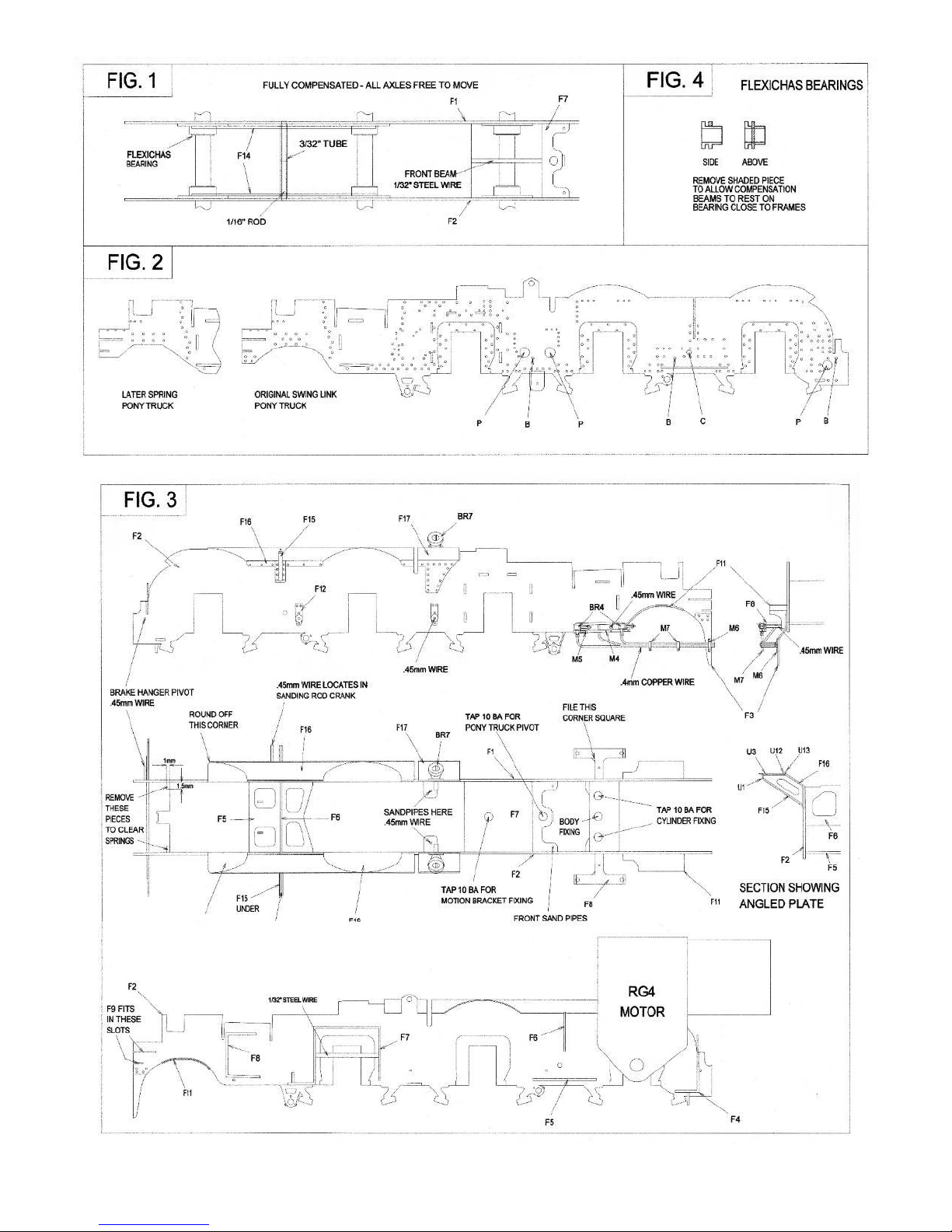
Solder the valve crosshead guides (parts BR1 or BR3 - front & BR2 - rear) in place aligning them with a piece of 0.8mm wire
passed through the valve rod holes. File away the back of the rear guides as shown in Fig.9.
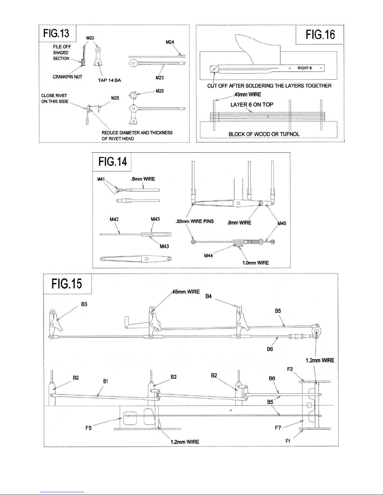
Construct the slidebars as shown in Fig. 16. Use plenty of solder whilst applying pressure to keep the laminations together.
Clean off the front and rear faces and remove the rear section. The crosshead slot will need cleaning out so that the crosshead
is a good fit. This can be done with a thin file - haven't gone one? - then use a piece of emery paper over a scrap piece of
brass etch. The appearance of the slidebars is much improved by carefully filing the top smooth.
Insert the slidebars in the cylinders and tack soldered in place. After checking all is square and parallel they are permanently
attached. Attach the piston rod glands (part NS2) and check that the crosshead slides properly. Attach the front covers (parts
NS3) and fit the relief valves (parts BR5). Add part M10 as shown in Fig. 9.
Solder together the connecting rod laminations (part M19 & M20) and add the rod boss laminations (part M21) to the big
end back and front. Drill the big end to fit the crankpins and the small end 1.0mm.
Solder the crosshead arm (part M39) to a piece of 1.0mm wire as a pin. Fit the connecting rod to the crosshead, ensuring the
crosshead arm is vertical, carefully solder the pin from the rear and file flush. Fit the connecting rods with a suitable washer
(part M50) between the coupling rods and connecting rods and check the clearance of the slidebar and crankpin nut. You
will possibly have to reduce the thickness of the nut. The connecting rod passes between the two lower slide bars and it will
be necessary to widen the gap between them to give clearance for the connecting rod to pass through.
SECTION 12: VALVE GEAR
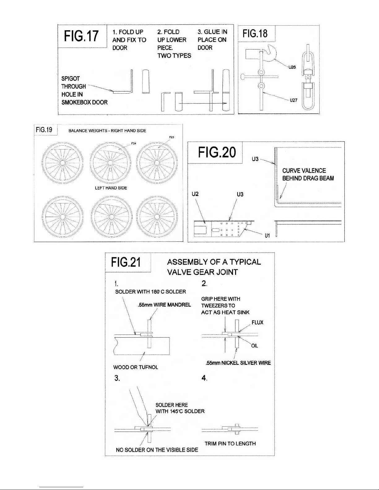
All the valve gear joints, with the exception of the eccentric arm/eccentric rod, are made with wire pins soldered on the
inside. This clearly runs the risk of soldering the joint solid. To minimise this:
(i) ensure the pin is a tight fit in the hole.
(ii) use oil or a proprietary solder mask.
(iii) use plenty of flux, a small amount of solder, and be quick!
Modify the motion bracket (part M11) to suit your frame spacing as shown in Fig. 9 and fold it up, with all fold lines on the
inside. Curve the lower ends of the motion bracket over a suitable rod to fit part M13. Solder part M13 in place in the groove
in part M11. Solder parts M12 in the grooves in parts M11 & M13 ensuring that the holes for the radius link pivot align
horizontally and vertically. Solder short pieces of 1.0mm wire to the brackets for the radius link pivots.
Drill out the holes in the radius link laminations (parts M26 & M27) to take the 0.3mm wire pins, which align the laminations
and represent the bolt heads. Solder the inner laminations together with 4 lengths of 0.3mm wire (Fig.11). Check that the
slot in the inner laminations is a sliding fit with the 0.7mm wire.
Place the radius rod (part M33) and radius rod front lamination (part M34) over the radius link, align with a piece of 0.7mm
wire, and solder the lamination to the rod. Solder the 0.7mm wire pin in place and clean off flush. The radius rod should now
move smoothly in the link. Add the fork joint (part M35) to the front of the radius rod. Open out the holes in the radius link
outer lamination (part M26) so that they are a good fit on the pivot wires on the radius link bracket. Solder the outer
laminations in place (N.B. they are not symmetrical –see Fig.11) and cut off the 0.3mm wire to represent the bolt heads.
Gently spring the links in place in the brackets (insert washers part M14 as shown in Fig.9) and check that the links pivot
freely and are vertical. Now remove the links and attach the reversing cranks (parts M28 & M29) using 0.7mm wire so that
they slide in the slots in the radius rods.
Attach the cylinders and motion bracket to the chassis with 10 BA screws. Check all alignments before soldering the motion

6
bracket to the slide bars.
Form the joggle in the combination levers (part M36) with the fold lines inside reinforcing the bends with solder. Assemble
the rear valve rods (part M40) and union link (parts M37 & M38). Pin together the combination lever, union link and valve
rod. Thread the radius rods through the hole in the motion bracket and pin to the combination levers. Carefully refit the
expansion links and add the reversing cross shaft from 1.0mm wire as shown in Fig.9.
Add the fork joint (part M24) to the eccentric rod (part M23). Reduce the diameter and thickness of the rivet heads so that
they will fit in the recess in the back of part M25. Tap the crankpin hole in the eccentric crank (part M22) 14 BA. Oil the tap
and use it to screw the eccentric arm and a crankpin nut together as shown in Fig.13. Now solder the nut to the arm. Remove
the tap and file off flange of the nut. This gives an arm with a substantial thread that can be tightened on the crankpin. Rivet
the radius rod to the arm and add part M25.
Fit the arms on the crankpin and tighten so that the offset of the end of the arm is 2.5mm (see Fig.27). You may need to file
some more off the nut so that it tightens in the correct position. Now pin the remaining two joints between the union link
and crosshead arm and between the radius link and eccentric rod. Check that the motion works smoothly. By rotating the
cross shaft you should now be able to reverse the motion!
Assemble the 2-to-1 arm (parts M42 & M43) and the front valve rods (part M41) as shown in Fig.14. Pin the left and middle
valve rods, 2-to-1 arm and equal arm (part M45) together. Solder a 1.0mm wire pin in place in the bracket attached to the
cylinders. Make the pin just long enough so that the 2-to-1 arm can be sprung in place over the washer (part M44). Adjust
the valve rods to length so that they do not interfere with the rear valve rods and check for free movement. Fit the right side
valve rod and pin to the 2-to-1 arm. Now link the valve rods together with hoops of 0.45mm wire (see Fig.9) checking that
you have equal backward and forward movement on the conjugated valve gear arms.
This now means that the valve gear is permanently fixed to the cylinders but the complete unit can be removed by unscrewing
the eccentric arms, cylinder screws and the screw attaching the motion bracket.
To ensure a good fit with the valence edge the cylinder wrappers (part M2 or M3) are best fitted after the upper works are
complete.
SECTION 13: FINAL CHASSIS DETAILING
Drill the holes in part F9 1.5mm to fit part WM4. Fold up part F9 (Fig. 6) inserting part WM4 at the same time. Attach parts
F10 and solder the complete assembly to the frames.
Attach the drain cock castings (part BR4) to part F8. Emboss the rivet on the drain cock linkage (part M4) and fold over the
end bracket at the front as shown in Fig.3, before soldering in place together with a length of 0.45mm wire to represent the
operating rod. Add part M5. Make the drainpipes from the 0.4mm copper wire provided, adding the brackets (parts M6 &
M7) as shown in Fig. 3. For the original pony truck the joggle in the pipes to clear the wheels is immediately behind the guard
iron.
The axles are now retained by the springs, formed from a triple lamination of parts F20, F21 & F22. The front springs will
need modifying to clear part F7. Assemble the brake hangers (parts B3 & B4) first embossing the rivet on each lamination.
Attach the hangers to the pivot wires. Emboss the bolts in parts B1 & B2 and solder the cross shaft overlays to the top of part
B1. Fix this assembly to the brake hangers. Complete the brake gear by fitting the front and rear cross shafts and pull rods as
shown in Fig.15.
Complete the chassis detailing by fitting sand pipes (0.45mm wire) as shown in Fig. 27.

7
SECTION 14: FOOTPLATE
Emboss the rivets on the valences and drag beam (part U1). Fold up the assembly –note there are two fold lines below the
drag beam and the fold should be made on the lower one. Curve the valence behind the drag beam as shown in Fig. 20.
Emboss the rivets on part U7 and add part U9. Fold up part U7 and solder in place behind the bufferbeam and between the
valences so that it is flush with their upper edges. Decide on the correct position of the lubricators (parts BR14 & BR15) and
drill out the appropriate locating holes in the footplate.
Carefully form the bends in the footplate by bending over a rod of suitable size. Now solder the footplate in place with the
valences in the half-etched recess along each side and part U7 in the recess under the front edge. Add part U2 to the rear
drag beam and a 10 BA nut over the middle hole at the rear and over the hole at the front. This now gives a sturdy platform
upon which to construct the upper works. The excess metal is not broken away until the boiler is fixed to the footplate.
Curve the outer edges of part U8 and locate in place over the lamp irons (See Fig.24). Locate the frame extensions (part U6)
and then solder up all the joints at the front end. Add the inner angle using parts U12, U13, U14, U15, U16 & U17 as shown
in Fig.23.
Fit the smokebox saddle casting (part WM10) to the footplate aligning it with the etched guide lines. Solder parts U18 & U19
or parts U23 to the footplate next to the saddle. For the original cylinder arrangement fix parts U20 & U21 together with
parts WM11 & WM12 in place. The outside steam pipes shown in Fig.24 are best left off until the boiler is fitted.
The front end detail can now be completed as shown in Figs. 22 & 24.
SECTION 15: FIREBOX
The boiler/firebox/cab assemblies are doweled together, using 0.8mm wire, for accurate location. An alternative to the use
of wire is 12 or 14 BA screws which are not provided.
Fold up the cab floor support (part C1) and use this as a jig to accurately make the bend in part U28. Pin together, using
0.45mm wire pins, parts U29, U30 & U31 as shown in Fig.26. Fold this assembly along the fold lines and locate together with
parts U28 and U32 to make the firebox cage. Before soldering together check that the 15.1mm dimension (see Fig.26) is
correct and adjust as necessary. Accuracy is very important at this stage if the firebox is to fit.
Clean out the slot for the sanding and reversing rods and round the sloping front edge. The edge of rear former must now
be chamfered as shown in Fig.26. Check that the dimensions are correct.
Solder parts U34 & U35 in place on the firebox wrapper (part U33) before forming the wrapper to shape. Centre the wrapper
on the formers by using the vee at the rear (accuracy here is essential) before tack soldering the wrapper in place. Note that
the lower edges at the rear will overhang the former at this stage so that when they are filed flush with the face of the former
they will fit against the cab front. When completely happy with the location of the former, solder it in place.
Fix parts U36 in place and the upper washout doors (parts U37). Solder handrail knobs in place and add the lower handrail
from 0.45mm wire.
SECTION 16: BOILER & SMOKEBOX
Form the coned boiler (part U40) by rolling and check for fit around the formers (parts U38 & U39). Bend the boiler band
joining brackets on part U41 and fit through the small slots from inside the boiler. If the fit is good and the formers fit then
solder the wrapper ends together with part U41. Solder the formers in place so that they are almost flush with the ends with
the wrapper aligned accurately with the cut out in the rear former. Check the boiler/firebox fit. Represent the bolts in the
joining brackets using 0.3mm wire and solder the handrail knobs in place.
Roll the smokebox/parallel boiler wrapper (part U45) and check the fit on the formers (parts U42 & U43). Solder the wrapper
ends together using part U46 and solder in the formers flush with the back and front with the line on part U43 aligned with
the wrapper join. Attach part U44 to the front of the smokebox aligning the handrail holes. Add the remaining handrail knobs.

8
Tap the hole in part U39 10 BA, so that the smokebox and boiler can be screwed together. Now check the fit of the
boiler/smokebox to the firebox and saddle. Form the ejector exhaust pipe from 1.0mm wire and attach using parts U50
through the slots in the boiler together with part BR18. Leave it over length as it passes through the cab front the rear. Add
the boiler handrails from 0.45mm wire.
SECTION 17: CAB
Solder the cab floor (part C2) to the cab floor support (part C1). Add the washout plugs from 0.5mm square wire.
Now form the bend between the cab sides and the cab front (part C5). To do this, first scribe, with a sharp point, the fold
lines (make them quite deep) on the inside. The lines run from the slots in the projections at the top and bottom. File off the
marking projections when satisfied and make the folds between the sides and front to match the cab floor. Solder the
spectacle window frames (part C6) in place on the inside. Solder the inner cab window layer (part C10) in place aligning the
small holes for the cab side windscreens (part C14). Solder the sliding window frame (part C11) over part C10 before breaking
off the rear piece along the etched line. The outer window layer (part C12) which retains the sliding window (part C13)
cannot be fixed until painting and glazing are complete.
Solder part C7 inside the rear edge of the cab sides and solder the cab handrails in place. Assemble the cab seats and fix in
place. Form the bend in the cab front and solder the cab sides and cab front to the cab floor. Decide on which fall plate you
require and fit as shown in Fig.25. The tabs on the hinged fall plate (part C3) are folded down and fit in the slots in the cab
floor to give a hinge effect. Form part C8 to shape and solder in place in the slots in the cab front. Solder the safety valves
(part BR11) in place in the holes in part C8.
Anneal the hinges on the cab doors (part C9), by heating in a flame and bend to shape around a 0.45mm piece of wire. The
hinge pins have been made too long so that they can be bent over to stop the doors falling off!
Fold up the back, front and central roof rib of part C15, to give a solid base upon which to build the removable cab roof. Roll
the cab roof, interior detail, and ventilator parts to shape. Solder part C17 in place, on the inside of the roof, as shown in
Fig.22, before soldering the roof in place on the former assembly. Complete by adding the ventilator parts and rain strips
(part C18). Now using a Carborundum disc in a mini-drill cut through the unwanted part of the former and snap off the
redundant parts along the etched lines. The edges of the formers will now need cleaning up.
SECTION 18: FINAL ASSEMBLY AND DETAILING
Now permanently attach the cab/firebox/boiler/smokebox to the footplate by fixing the smokebox to the saddle and bolting
the footplate to the cab. It may be possible to arrange a non-permanent fixing to the saddle to make painting the model
easier but care will be needed in handling the footplate once the redundant material is removed. Remove this unwanted
material in the same way as for the cab roof.
Solder the mechanical lubricators (parts BR16) in position as shown in Fig. 23. Thread parts M46 & M47 through the footplate
holes and locate on the lubricator spindles, but do not solder in place yet. Fold over the crank on part M48, with the fold line
on the outside before soldering in place in the etched recesses under the footplate. Link parts M46, M47 & M48 with a piece
of 0.45mm wire. Add parts M30, M31 & M32 as shown in Fig. 23.
Attach all the remaining parts using the drawings and photographs as a guide to position.
Using the drawing of the cab interior the back plate can be assembled and the cab interior detailed. Use the 0.7mm copper
wire for the pipes.
If you have any problem with the kit or any criticisms or suggestions please contact Brassmasters.
Best wishes
Martin Finney March 2001

9

10

11

12

13

14

15

16

17

18

19
Table of contents
Other Brassmasters Toy manuals

Brassmasters
Brassmasters EasiChas User manual

Brassmasters
Brassmasters A1 4-6-2 User manual

Brassmasters
Brassmasters EasiChas User manual

Brassmasters
Brassmasters EasiChas User manual

Brassmasters
Brassmasters BULLDOG User manual

Brassmasters
Brassmasters EasiChas User manual

Brassmasters
Brassmasters GWR 3000 User manual