Brassmasters A1 4-6-2 User manual

Brassmasters
Scale Models
www.brassmasters.co.uk
GREAT NORTHERN RAILWAY
LONDON & NORTH EASTERN RAILWAY
A1 / A3 4-6-2
(Right-hand drive)
LOCOMOTIVE KIT
Designed by Martin Finney
4MM SCALE
OO - EM - P4
INSTRUCTIONS
AND PROTOTYPE NOTES
PO Box 1137 Sutton Coldfield B76 1FU
Copyright Brassmasters 2016

1
SECTION 1: BRIEF HISTORICAL DETAILS
Just before Grouping, Nigel Gresley introduced his prototype 4-6-2 design on the G.N.R. There were only two engines
of this class in service at the end of 1922, but a further ten had been ordered by the G.N.R. and these were completed
in 1923, the L.N.E.R. classification being A1. On Gresley's appointment as C.M.E. of the L.N.E.R. this class was adopted
as standard and a further forty (twenty by the North British Locomotive Company) were constructed in 1924-25. In
1927 two of the class were rebuilt with higher pressure boilers to become the first of class A3 and eventually, by 1948,
all but the first engine was dealt with in this fashion. These engines were all built with the driving position on the right
hand side.
E.O. Original Post 1924 Built Builder
Numbers Numbers
293 1470/71 4470/71 4/1922-7/1922 Doncaster
1472-9 4472/79 2/1923-7/1925 Doncaster
297 1480/81N 4480/81 2/1930-7/1930 Doncaster
301 2543-52 7/1934-2/1935 Doncaster
302 2553-62 12/1924-7/1925 Doncaster
L787 2563-82 8/1924-12/1924 North British
From this kit, which is for right hand drive engines, you can build these engines in their original condition as class A1 or
after their conversion to class A3, until circa 1952-54, when they were eventually converted to left hand drive.
For a detailed history of this long lived class Part 2A of Locomotives of the L.N.E.R. published by the R.T.C.S. is essential
reading. Other valuable sources of information and photographs are:
Locomotives Illustrated 25 - Ian Allan
The Gresley Pacifics - O.S.Nock - David & Charles
Yeadon's Register of L.N.E.R. Locomotives - Volume One - Irwell Press
East Coast Pacifics at work - P.N.Townend - Ian Allan
The Power of the A1s, A2s and A3s - J.S.Whiteley & G.W.Morrison - Oxford Publishing Co.
Variations/Modifications incorporated into the kit
Cabs: The first eleven engines were built to the generous G.N.R. loading gauge with high cabs. The remaining engines,
except for 1481N, were built to the reduced, composite L.N.E.R. loading gauge with lower cabs. The first eleven had
their cabs altered to conform between 1928 and 1933.
Cab sides: on the lower cabs the original cut-out was increased in height by 11" at the same time as bucket seats fitted.
Chimney: original high type for G.N.R. loading gauge and lower type for the L.N.E.R. composite loading gauge.
Dome: original high type for G.N.R. loading gauge and lower type for the L.N.E.R. composite loading gauge plus the two
types of banjo domes fitted to the A3 class with the later 94A boiler from 1940 onwards.
Firebox: All the fireboxes fitted to A1 class boilers (Diagram 94) and to the first five A3 class conversions (Nos. 4480,
2544/73/78/80) designated diagram 94 HP were similar in appearance with four washout plugs on the left hand side,
and three on the right. With the next batch of 94 HP boilers washout plugs were increased by one each side as shown
in Fig. 28.
Firebox crown washout plugs/door covers: Originally square ended plugs and from circa 1936 onwards circular covers.
Safety valves: original large type for G.N.R. loading gauge and smaller type for the L.N.E.R. composite loading gauge.
Frames: Differing frame lightening hole arrangements. In their original condition these engines had four large oval
holes together with a 12" circular hole ahead of the cylinders. However due to the surprising frequency with which
frames were replaced or repaired the large holes either disappeared, were plated in from inside or were replaced by
the 12" circular holes that were standard on the later new A3s.
Frame rivets: The original engines were built using countersunk rivets and so give a smooth appearance to the frames.
Many photographs show a gradual change to rivets with a visible head as frames were repaired or replaced.
Valve gear: All the engines were originally built with short travel valve gear (STV) with narrow platforms and
steampipes which extended down to the level of the footplate. Between March 1927 and May 1931 they were rebuilt

2
with long travel valve gear (LTV) with wider platforms and shorter steampipes. This change alters the length of the
crosshead arm and the arm below the radius link.
Bogie: Originally the engines were built with the swing link bogies which were converted to the helical spring type
circa 1933-34.
Bufferbeam: The first twelve engines had a rectangular bufferbeam. The corners were subsequently cut away to clear
at the platforms at Newcastle, as shown in the diagrams, later engines being built with this modification.
Front footsteps: Nos. 1472 - 81 were originally equipped with a light bar iron type. These were all removed by 1927.
From 1935 onwards all the engines were fitted with a plate type and at the same time small grab handles were fitted to
the front drop plate.
Rear Steps: Nos. 1470 -80 were built with a width of 8' 8" over the steps. The remainder were built with narrower steps
with an overall width of 8' 4".
Front end cover plates: Small cover fitted from 1933 onwards.
Rear spring retaining brackets: Fitted later.
Anti-vacuum valve plate - Two types provided.
Cab seats: original type replaced with bucket seats from circa 1935 onwards.
Lamp irons - footplate: second lamp iron on R.H.S. removed from 1931.
Lamp iron - smoke box door: two different types.
Reversing rod: Different shape depending on whether Doncaster or North British built.
SECTION 2: CHASSIS DETAILS
Note that many of the components for both chassis and body are handed left/right and care must be taken to ensure
the correct component is used. I have not always identified left/right components separately but with care and
common sense no problems should arise.
Before construction can commence you have to decide which chassis you are going to construct. The options are:
1. Gauge 00, EM or 18.83.
2. Suspension Rigid, sprung, compensated.
3. Pick-ups Scraper, plunger or the 'American' system.
No pick-up material is provided. The options are:
Scrapers attached to printed circuit board fixed between the frames.
Plunger - drill out three of the holes P1 or P2 on each side and fit according to the manufacturer’s
instructions.
The 'American' system with the wheels on the loco are shorted out on one side and the tender on the
other. I have produced some etched shorting strips, as an additional item, for this purpose. The drawbar
between the loco and tender can be used to carry the current.
SECTION 3: FRAMES
Having decided which chassis to construct you can now start construction by preparing the frames (parts 1 & 2). First
emboss, using photographs as a guide, the appropriate rivets.
For a rigid chassis open out the main axle holes to accept 1/8" top hat bearings (not provided) and solder them in
place. If you are going to fit sprung horn blocks, you should remove the axle holes by cutting up the half-etched lines,
leaving a standard 6mm wide slot and then follow the manufacturer’s instructions.
To construct the kit as designed with a compensated chassis, first decide which of the two possible compensation
arrangements you prefer (Fig.1). Remove the appropriate axle holes as described above. Carefully widen the slot in the
hornblocks (part 9) until the Flexichas bearings are a good fit. I find a significant variation in the bearings and once I
have fitted a hornblock to a bearing I mark the bearing and hornblock so that they can be later assembled together. A
good fit between hornblock and bearing is essential if the chassis is to run well.

3
For the fully compensated arrangement, which gives a much smoother ride to the chassis, drill out holes P1 for plunger
pick-ups and C1 (1/16") for the compensation beam and solder the rear hornblocks to the inside of the frames, aligning
them with the half-etched line and with the bottom of the frames.
For the simpler system, drill out holes P2 and C2 and solder top hat bearings in place for the rear axle.
Drill holes B for brake hanger pivots - 0.45mm. Bend the lubricator linkage brackets along the fold lines at right angles
and strengthen with a fillet of solder. The front bracket will need relieving slightly to clear the driving wheel. Fold up
the centre sandboxes as shown in Fig.4. Solder in place parts 84, 95 & 96 and the brake hanger pivots from 0.45mm
wire (Fig.3).
SECTION 4: FRAME STAYS AND ASSEMBLING THE CHASSIS
Remove parts 5, 6, 7, 8, and 83 to suit your chosen gauge. Open out the holes for the front compensation beam in part
7 to 0.8mm. Fold up parts 5, 7 & 8 making sure the half-etched fold line is on the inside and that each bend is a right
angle.
Check that all tabs on the stays fit properly in their corresponding chassis slots so that the rest of the stay is hard up
against the inside of the frames. Tap the cylinder fixing holes in part 8 10 BA. Solder one of the longer 10 BA bolts
through the hole in part 8, for the bogie pivot.
Now assemble the frames and stays. Note the shorter side of part 83 is on the right. Start by tack soldering part 7 to
both sides. Check that everything is square and that the stays are hard against the frames. Put an axle (or better a
longer piece of 1/8" rod) through the rear bearings and place the chassis on a piece of graph paper to check that the
axle is square to the frames.
If all is well, solder the remaining stays to the frames checking constantly that the chassis is square and the frames are
straight and checking that the rear of part 5 will be vertical. Solder part 97 in place and add part 98 to the lower edge of
part 83 and trim to length. Attach the bogie splashers (parts 104 & 105) locating them in the frame cut-outs.
SECTION 5: COUPLING RODS
The coupling rods are now made so that they can be used as a jig to align the remaining hornblocks accurately. First,
drill out all the crankpin holes to a convenient size which is well undersize for the crankpins and the fork joint holes
1mm so that the 1mm nickel silver wire is a tight fit. Remove all burrs caused by the drilling. Now drill a hole, with the
drill used for the crankpin holes, in a small block of wood and leave the drill in the wood with its shank projecting. This
projecting shank is used as a mandrel to accurately align the laminations of each rod.
Place the laminates over the mandrel and using plenty of solder and flux solder the two laminates together. You will
now have rods with the crankpin and fork joint holes aligned. Carefully file the edges so that the 'laminated' effect is
lost and the rods appear to be made from one piece of metal.
The crankpin holes now need carefully opening out until they just fit, with no free play, the ends of the hornblock
alignment jigs (available from London Road Models or Markits).
The fork joints are now pinned using the 1mm nickel silver wire. Retain the pins, which should be a tight fit, by lightly
soldering on the inner face of the rods. The correctly assembled rods should now have a completely flush inner face.
SECTION 6: FITTING THE FLEXICHAS HORNBLOCKS
Prepare the remaining bearings and hornblocks as described in section 3 and slide them over the hornblock alignment
jigs with the springs between the bearings. Carefully compress the springs and clip the hornblocks between the frames
and place the prepared coupling rods over the ends of the jigs. Make sure the hornblocks are square to the chassis and
that their bottom edge aligns with the lower edge of the frames and then solder them in place.

4
SECTION 7: FITTING THE COMPENSATION BEAMS
For the fully compensated arrangement solder a piece of 0.8mm wire through the holes in part 7. For the rear beams
cut a piece of 1/16" brass rod so that it fits through the holes C1 and is flush with the outside face of the chassis
frames. Cut two equal pieces 3/32" tube which together fit between the frames and solder the rear beams (part 10) to
them close to one end. Modify the flexichas bearings on the two rear axles as shown in Fig.1 and temporarily fit the
beams.
For the simpler system fix both beams (part 10) centrally to a piece of 3/32" tube as shown in Fig.1.
Temporarily fit all the wheels and axles and confirm that the compensation works properly and check that the chassis is
sitting level. Retain the beam pivot by fitting part 117 over the brake hanger pivots as shown in Fig.3.
SECTION 8: REAR FRAMES AND RADIAL TRUCK
Fold in the radial truck hornguides on part 3 (Fig.7). Now make all the bends on part 3 - all 90° and with fold lines inside
- then solder in place on the rear of part 5 ensuring that the rear frame will be level. Emboss the rivets on the outer
frames (part 85) and form to fit. Fold up part 4 and locate between the rear frames. Check all is fitting correctly before
soldering the rear frames in place. Detail the rear frames by adding the rear steps (parts 86 & 87 or 88 & 89) and parts
90, 91 & 92 together with the Cartazzi axlebox ties from 0.7mm wire.
Bend part 94 to shape and solder around part 93 to make the lower firebox. Add the washout plugs at the corners from
0.5mm square wire and the blowdown tap (part B8) before soldering in place on top of part 3.
Fold up the spring wire brackets and side play stops on part 17. Fold up part 18 and attach part 17 and check for free,
but not sloppy, movement in the hornguides. Solder the small top hat bearings in place and fit the radial truck wheels
using the washers (part 120) to eliminate any side play. Bend up the spring wire to give some downward pressure and
solder in place through the bracket on part 3 and the hole in part 5. The radial truck is retained with lengths of 0.5mm
square wire.
SECTION 9: BOGIE
Emboss all the frame rivets as shown in Fig.10 and solder the top hat bearings in place. Fold up the guard irons (part
103) and solder in place on the inside of the frames. Fold up the frame stay (part 102) and reinforce the spring wire
retaining brackets with a fillet of solder. Solder the frames and frame stay together and add parts 15 and 16. Form the
dust shields (part 106) to shape and solder in place.
Using appropriate washers (part 120) fit the wheels so that there is a minimum of side play. Bend up the spring wire to
give some downward pressure and solder in place through the holes in part 7. The bogie is retained with a 10 BA nut.
SECTION 10: COMPLETING THE CHASSIS MECHANICALLY
Fit the crankpins to the wheels making sure the screw heads do not foul, countersinking them if necessary. Attach the
balance weights to the wheels as in Fig. 16. Assemble the wheel sets, bearings and motor/gearbox selecting 1/8" axle
washers of appropriate thickness to control side play. Side play on the leading axle should be kept to a minimum to
avoid clearance problems with the valve gear and connecting rod.
The cranks on the right hand side should lead the left by 120°. I find the easiest way to achieve this consistently on all
three axles is by looking through the wheels with a magnifier against a strong light and lining up corresponding spokes.
The wheels have 20 spokes which gives 18° between each spoke. 120 is unfortunately not a multiple of 18 but 18° x 7 =
126° which is close enough. So you simply adjust the wheel sets until the right hand side is seven spokes ahead of the
left. This method is surprisingly accurate and, for me at least, gives by far the best results. Now connect the motor to
your pick-ups and test run.
SECTION 11: CYLINDER ASSEMBLY
Check all the holes in the cylinders (part 26) against the appropriate components and open up the holes if necessary. If
you are building an EM or 18.83 chassis reduce the width of the inside cylinder faces to the etched lines provided so

5
that the cylinders are a good fit it the slots in the frames. Fold up the cylinders making sure they are square and fold
out the 2-to-1 arm bracket.
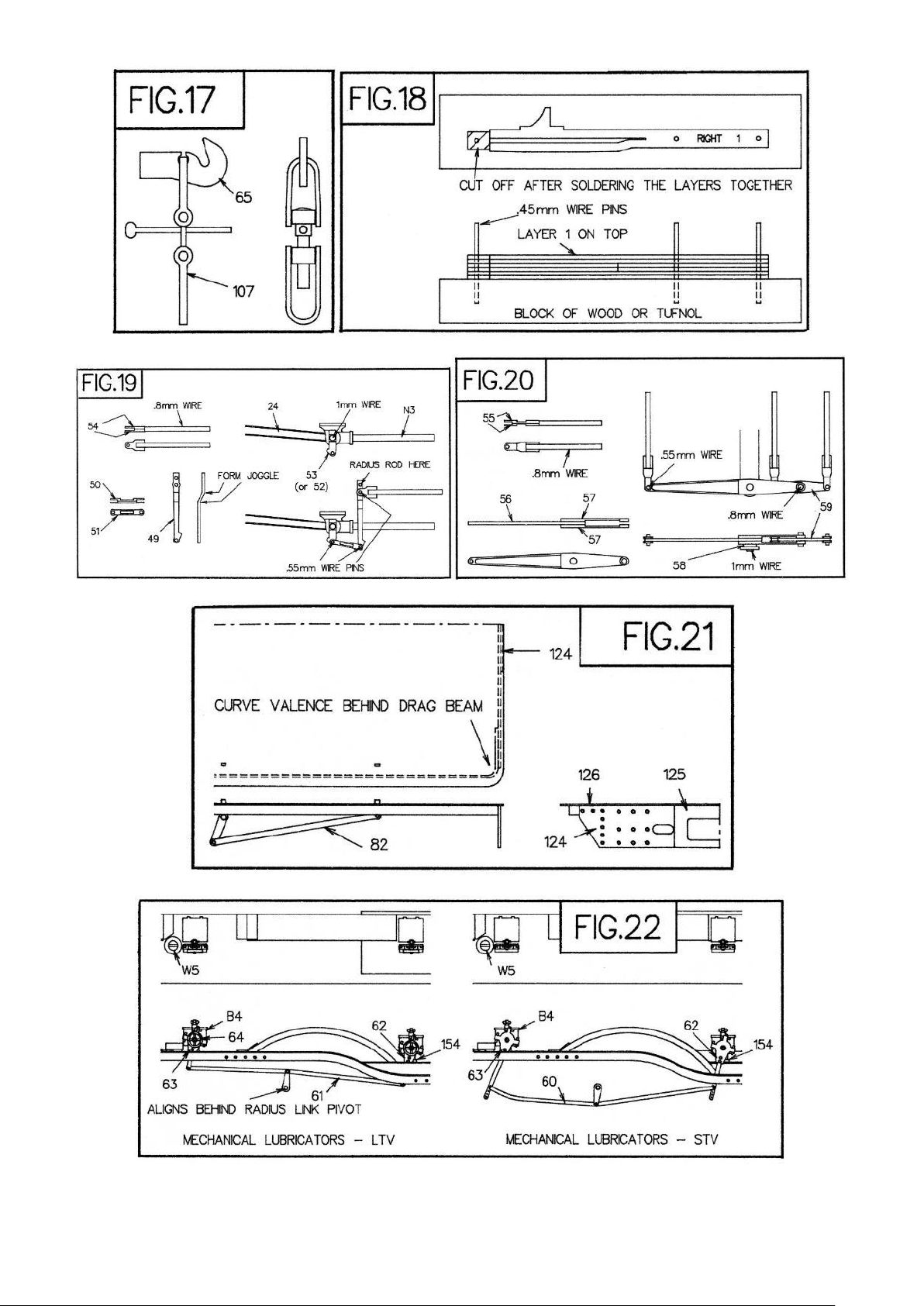
Construct the slidebars as shown in Fig. 18. Use plenty of solder whilst applying pressure to keep the laminations
together. Clean off the front and rear faces and remove the rear section. The crosshead slot will need cleaning out so
that the cross head is a good fit. This can be done with a thin file - haven't gone one? - then use a piece of emery paper
over a scrap piece of brass etch. The appearance of the slidebars is much improved by carefully filing the top smooth.
Insert the slidebars in the cylinders and tack soldered in place. After checking all is square and parallel they are
permanently attached. Attach the piston rod glands (part N4) and check that the crosshead slides properly. Solder the
valve crosshead guides (parts B17 & B18) in place aligning them with a piece of 0.8mm wire passed through the valve
rod holes.
The cylinder relief valves (part B3) were a later addition. If photographs shown you need to fit them drill out the holes
in the front cylinder covers (part N5 & N6) - marked on the inside - so that the relief valves will pass through. Attach the
front covers and, if appropriate, fit the relief valves. Add part 29 as shown in Fig. 9.
Solder together the connecting rod laminations (part 23 & 24) and add the rod boss laminations (part 25) to the big end
back and front. Drill the big end to fit the crankpins and the small end 1mm. Solder the crosshead arm (part 52 or 53) to
a piece of 1mm wire as a pin. Fit the connecting rod to the crosshead, ensuring the crosshead arm is vertical, carefully
solder the pin from the rear and file flush. Fit the connecting rods with a thin washer (part 109) between the coupling
rods and connecting rods and check the clearance of the connecting rod and the leading axle crankpin nut. You will
probably have to reduce the thickness of the nut.
Solder the slide bar bracket laminations (part 30) together back to back. Attach the cylinders to the chassis with two 10
BA bolts and fit the slide bar bracket through the frame slots and solder to the slide bars.
SECTION 12: VALVE GEAR
All the valve gear joints, with the exception of the eccentric arm/eccentric rod, are made with wire pins soldered on the
inside. This clearly runs the risk of soldering the joint solid. To minimise this:
(i) ensure the pin is a tight fit in the hole.
(ii) use oil or a proprietary solder mask.
(iii) use plenty of flux, a small amount of solder, and be quick!
Bend up, in a vice, part 37 centring the bends on the etched slot. Solder part 38 in the slot in part 37 ensuring that the
holes for the radius link pivot align horizontally and vertically. Solder the radius link brackets to part 39 as in Fig.11 and
check the assembly fits in the frame slots. Solder short pieces of 1mm wire to the brackets for the radius link pivots.
Drill out the holes in the radius link laminations (parts 34 & 35 or 36) to take the 0.3mm wire pins which align the
laminations and represent the bolt heads. Solder the inner laminations together with four lengths of 0.3mm wire
(Fig.12). Check that the slot in the inner laminations is a sliding fit with the 0.7mm wire.
Place the radius rod (part 46) and radius rod rear lamination (part 47) over the radius link, align with a piece of 0.7mm
wire, and solder the lamination to the rod. Solder the 0.7mm wire pin in place and clean off flush. The radius rod
should now move smoothly in the link. Add the fork joint (part 48) to the front of the radius rod. Open out the holes in
the radius link outer lamination (part 34) so that they are a good fit on the pivot wires on the radius link bracket. Solder
the outer laminations in place and cut off the 0.3mm wire to represent the bolt heads. Gently spring the links in place
in the brackets (insert washer part 40 as shown in Fig.40) and check that the links pivot freely and are vertical.
Form the joggle in the combination levers (part 49) with the fold lines inside reinforcing the bends with solder.
Assemble the rear valve rods (part 54) and union link (parts 50 & 51). Make the valve rods as long as possible so that
they just go in past the slide bar bracket. Pin together the combination lever, union link, valve rod and radius rod.
Add the fork joint (part 33) to the eccentric rod (part 32). Reduce the diameter and thickness of the rivet heads so that
they will fit in the recess in the back of part 108. Tap the crankpin hole in the eccentric crank (part 31) 14 BA. Oil the
tap and use it to screw the eccentric arm and a crankpin nut together as shown in fig.14. Now solder the nut to the
arm. Remove the tap and file off flange of the nut. This gives an arm with a substantial thread which can be tightened

6
on the crankpin. Fit the arms on the crankpin and tighten so that the offset of the end of the arm is 2.5mm. You may
need to file some more off the nut so that it tightens in the correct position. Rivet the radius rod to the arm and add
part 108.
Now pin the remaining two joints between the union link and crosshead arm and between the radius link and eccentric
rod. Check that the motion works smoothly. Fit the reversing crank (parts 41 & 42) to the reversing cross shaft made
from 1mm wire as in Fig.11. Add the pins through the ends of the cranks and through the slots in the radius rods. By
rotating the cross shaft you should now be able to reverse the motion!
Assemble the 2-to-1 lever (parts 56 & 57) and the front valve rods (part 55) as shown in Fig.17. Pin the valve rods, 2-to-
1 lever and equal lever (part 59) together. Solder a 1mm wire pin in place in the bracket attached to the cylinders.
Make the pin just long enough so that the 2-to-1 arm can be sprung in place over the washer (part 58). Adjust the valve
rods to length so that they do not interfere with the rear valve rods and check for free movement.
Now link the valve rods together with loops of 0.3mm wire (see Fig.9) checking that you have equal backward and
forward movement on the conjugated valve gear arms. This now means that the valve gear is permanently fixed to the
cylinders but the complete unit can be removed by unscrewing the eccentric arms and cylinder bolts.
Form the cylinder wrappers (part 110) to shape and solder in place making sure the drain cock holes are on the bottom
centre line. Attach the drain cock castings (part B2). Emboss the rivets on the drain cock linkage (part 111) and joggle
the front lever as in Fig.9, before soldering in place together with lengths of 0.45mm wire to represent the operating
rods.
SECTION 13: FINISHING THE CHASSIS
The axles are now retained by the springs, formed from a triple lamination of parts 11, 12 & 13. Assemble the brake
hangers (parts 115 & 116) first embossing the rivet on each lamination. Attach the hangers to the pivot wires. Emboss
the bolts in parts 112 & 113 and solder the cross shaft overlays to the top of part 112. Fix this assembly to the brake
hangers. Complete the brake gear by fitting the front cross shaft, levers, pull rods and brake cylinders (parts 114 &
W16) as shown in Fig.13.
Complete the chassis detailing by fitting sandboxes (part W15), sand pipes (0.45mm wire) and sand box filler pipes
(1mm wire) as shown in Fig.4.
SECTION 14: FOOTPLATE
Emboss the rivets on the valences (part 124) and fold up. Now emboss the rivets on the drag beam and buffer beam as
appropriate and fold up. There are two fold lines below the drag beam and the fold should be made on the lower one.
Curve the valence behind the drag beam as shown in Fig. 21. Fold up part 129 and solder in place behind the
bufferbeam and between the valences so that it is flush with their upper edges. Carefully form the bends in the
footplate by bending over a rod of suitable size and fold up the strengthening ribs either side of the body fixing nut.
Now solder the footplate in place with the valences in the half-etched recess along each side and part 129 in the recess
under the front edge. Add part 125 to the rear drag beam and a 10 BA nut over the middle hole at the rear. This now
gives a sturdy platform upon which to construct the upper works. The excess metal is not broken away until the boiler
is fixed to the footplate.
Curve the outer edges of part 130 and locate in place over the lamp irons (See Fig.23). Locate the frame extensions
(part 80) and then solder up all the joints at the front end. Fit the smokebox saddle castings (part W24) between the
frames aligning them with the half-etched lines on the inside of the frames. The front casting will need shortening the
joint between the two pieces being hidden by the steampipes.
Locate the half-etched groove in the splasher fronts (parts 140,141 & 142) on the footplate edge and solder in place in
the centre of each opening. Curve the splasher tops (parts 143,144 & 145) to shape by rolling underneath a suitable rod
or dowel on a resilient surface (a piece of rubber sheet). Emboss the rivets, and fold up the end brackets before
soldering in place. Add part 146 as shown in Fig.26. Fold up the valve cover box bases (part 132 or 135) and solder in
place on the footplate. They are correctly located when the square holes in the footplate and the base align. Fold up
the valve cover box side (part 133 or 136) and solder in place against the edge of the base. Form part 138 and solder in
place on part 134 or 137 before soldering part 134 or 137 in place.

7
The front end detail can now be completed by adding parts 127, 128, B5, W4, 139, & 131 as appropriate. Add the
sanding rods as shown in Fig. 26 and the lubricators as shown in Fig. 22. The lubricator linkage (part 60 or 61) is fixed to
the chassis brackets and is probably best left until the body can be fixed to the chassis.
SECTION 15: FIREBOX
Do not remove the cusp around the edges of the firebox and boiler formers or they will be too small.
Pin together, using 0.45mm wire pins, parts 69, 70, 71 as shown in Fig.27 with the part 71 with the cut-outs for the
sanding and reversing rods on the right side. Fold this assembly along the fold lines and solder together with parts 68
and 72 to make the firebox cage. Open up the slots for the sanding and reversing rods and round the sloping front
edge.
Drill holes for the extra washout plugs in the firebox wrapper (part 155), if appropriate, as shown in Fig. 28. Solder parts
73 & 74 in place before forming the wrapper to shape. Centre the wrapper on the formers by using the small notches in
the top of the formers (accuracy here is essential) before soldering the wrapper in place. Solder two short pieces of
0.7mm wire into the holes in the rear former to act as dowels to locate the firebox and cab. Alternatively, 12 BA screws
could be used. Fix part 156 in place and the upper washout plugs/doors as appropriate. Solder handrail knobs in place
and add the lower handrail from 0.45mm wire.
SECTION 16: BOILER AND SMOKEBOX
Form the coned boiler (part 159) by rolling and check for fit around the formers (parts 75 & 76). Bend the boiler band
joining brackets on part 160 and fit through the small slots from inside the boiler. If the fit is good and the formers fit
then solder the wrapper ends together with part 160. Solder the formers in place so that they are almost flush with the
ends with the etched notch at the top of the rear former aligned accurately with the notch in the wrapper. Solder two
short pieces of 0.7mm wire into the holes in the rear former to act as dowels to locate the boiler and firebox.
Alternatively, 12 BA screws could be used. Check the boiler/firebox fit. Represent the bolts in the joining brackets using
0.3mm wire and solder the handrail knobs in place.
Emboss the rivets around the ejector exhaust pipe flange on the smokebox/parallel boiler wrapper (part 161) and mark
out and drill the missing handrail knob holes as shown in Fig.23 or Fig.24. Roll the wrapper and check-fit it on the
formers (parts 77 & 78). Solder the wrapper ends together using part 162 and solder in the formers flush with the back
and front with the two handrail knob holes on the front spacer equally spaced from the adjacent holes on the wrapper.
Drill out the handrail knob holes in part 79 and attach to the front of the smokebox aligning the handrail holes. Add the
remaining handrail knobs.
Tap the hole in part 77 10 BA so that the smokebox and boiler can be screwed together. Now check-fit the
boiler/smokebox to the firebox and saddle.
Form the ejector exhaust pipe from 1mm wire and attach using part 166 through the slots in the boiler. Leave it over
length as it passes through the cab front at the rear. Add the boiler handrail from 0.45mm wire.
SECTION 17: CAB
Fold up the cab floor support (part 170) and solder the cab floor (part 171) in place. Add the washout plugs from
0.5mm square wire. Curve the rear edges of the cab sides (part 175, 176 or 177) and solder part 178,179 or 180 inside
the rear edge. Solder the cab doors (part 181 or 182) to the hinges and solder the cab handrails in place. Solder the
inner cab window layer (part 183) in place. For the low cab, align the small holes for the cab side windscreens (part
187). Solder the sliding window frame (part 184) over part 183 before breaking off the rear piece along the half-etched
line. The outer window layer (part 185) which retains the sliding window (part 186) cannot be fixed until painting and
glazing are complete. Assemble the cab seats and fix in place.
Emboss the rivets on the cab front (part 173 or 174). Solder the cab sides and cab front to the cab floor. Fold down the
tabs on the fallplate (part 172) which fit in the slots in the cab floor to give a hinge effect.
Fold up the back and front of part 188 or 189 which gives a solid base upon which to build the removable cab roof. Roll
the cab roof to shape and solder in place with the cut-out for the ventilator on the low roof (part 191) as far forward as
possible. Complete by adding the ventilator and rainstrips as shown in Figs. 30 & 31. Now using a Carborundum disc in

8
a mini-drill cut through the unwanted part of the former and snap off the redundant parts along the half-etched lines.
The edges of the formers will now need cleaning up.
The ends of rear roof former of the low roof are curved round to fit between the cab sides. Those of the high roof fit
between the cab sides behind the inner beading.
SECTION 18: FINAL ASSEMBLY AND DETAILING
Now permanently attach the cab/firebox/boiler/smokebox to the footplate by soldering the smokebox to the saddle
and bolting the footplate to the cab. It may be possible to arrange a non-permanent fixing to the saddle to make
painting the model easier but care will be needed in handling the footplate once the redundant material is removed.
Remove this unwanted material in the same way as for the cab roof. The bufferbeam and lower front edge of the
valence can now be modified, if appropriate, by filing to the lines on the inside as shown in Figs. 23 & 24.
Fold up part 99 (Fig. 6) removing the steps if appropriate. Attach the front steps (parts 100 & 101) and solder the
complete assembly to the frames.
Attach all the remaining parts using the drawings and photographs as a guide to position.
Using the drawing of the cab interior the backplate can be assembled and the cab interior detailed. Use the copper
wire for the pipes.
If you have any problem with the kit or any criticisms or suggestions, please feel free to contact me.
Finally I must again thank Guy Williams for the original idea of a 'foreign' Pendon locomotive and for much of the
pattern making.
Best wishes
Martin Finney
February 1994
If you have any problem with the kit or any criticisms or suggestions please contact Brassmasters.

9

10

11

12

13

14

15

16

17

18

19
This manual suits for next models
1
Table of contents
Other Brassmasters Toy manuals

Brassmasters
Brassmasters LNER V2 2-6-2 User manual

Brassmasters
Brassmasters EasiChas User manual

Brassmasters
Brassmasters GWR 3000 User manual

Brassmasters
Brassmasters EasiChas User manual

Brassmasters
Brassmasters BULLDOG User manual

Brassmasters
Brassmasters EasiChas User manual

Brassmasters
Brassmasters EasiChas User manual
Popular Toy manuals by other brands

Amewi
Amewi HYDRAULIK BAGGER manual

Eduard
Eduard P-38L Lightning interior set quick start guide

Fisher-Price
Fisher-Price BFH68 quick start guide

Fisher-Price
Fisher-Price WILD ADVENTURES Smithsonian 77897 instructions

Fancy Foam Models
Fancy Foam Models EPP 3Decathlon Assembly instructions

AE
AE RC10 Team Car Assembly manual