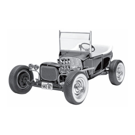
Brassmasters BULLDOG User manual

Brassmasters
Scale
Models
www.brassmasters.co.uk
GREAT WESTERN RAILWAY
‘BULLDOG’ AND ‘BIRD’ 4-4-0
LOCOMOTIVE KIT
Designed by Martin Finney
4MM SCALE
OO - EM - P4
INSTRUCTIONS
AND PROTOTYPE NOTES
PO Box 1137 Sutton Coldfield B76 1FU
Copyright Brassmasters 2015

1 v.1
SECTION 1: BRIEF HISTORICAL DETAILS
For a detailed history of this large (156 engines) and long lived class Part Seven of 'The Locomotives of the Great Western
Railway’ published by the R.C.T.S, is essential reading. From this kit any of the straight framed engines (the last 115
built) can be built from circa 1904 to 1951.
In designing the kit I used the following Swindon drawings:
16116 2/1900 Lot 124/137 Frame plan
36557 1/1909 Lot 177 Frame plan
25816 9/1904 Lot 124 Front elevation
36774 6/1908 Lot 177 Cab & splashers
115623 10/1940 Inside motion
The straight framed engines were built in seven Lots as follows:
Lot
Old Nos.
New Nos.
Built
Cab
Boiler new
Frames
Nameplates
124
3353-72
3341-60
1/00-12/00
1
D0
Std 1
Oval
137
3413-32
3361-80
12/02-5/03
2
D0
Std 2
Standard
142
3443-52
3381-90
9/03-10/03
2
D2
Std 2
Standard
148
3453-72
3391-3410
1/04-4/04
2
D2
Std 2
Standard
162
3701-15
3411-25
4/06-6/06
2
D3
Std 2
Standard
163
3716-30
3426-40
7/06-9/06
2
D3
Std 2
Standard
177
3731-45
3441-55
5/09-1/10
2
D3
Deep
Standard
For convenience I shall from now on refer to Lots 124, 137, 142, 148, 162 & 163 with the 'standard’depth of outside
frame as 'Bulldogs’ and to Lot 177 with the ’deep’frames as ‘Birds’.
Lot 124 differed from the later 'Bulldogs’because of the smaller cab cut-out (Cab 1) and curved rear steps (Frames Std
1).
Two boilers are provided in the kit: the D2 half-coned and the D3 three quarter-coned. This means that Lots 124 and
137 cannot be built in their original condition with the D0 parallel boiler.
Because the outside frames of the kit have the snap head rivets half etched Lots 124, 137 & 142 cannot be built in their
original condition with flush frame rivets. The first Lot, therefore, that can be built in original condition is Lot 148.
The early Lots can of course be built in slightly later condition as they appear to have acquired frame strengthening
plates and snap head rivets surprisingly quickly, probably during their first major shopping. Lot 163 was built with the
frame strengthening plates and the 'Birds1 also were built with them but only on the rear axle.
'Bulldogs' originally had Dean 'swing-hanger’bogies, fluted coupling rods, steam brake and steam reverse whereas the
'Birds' were built with ’De Glehn’type bogies, plain coupling rods, vacuum brake and screw reverse.
There are also many detail differences both between individual locomotives and as the class changed through time.
The following are possible with the kit.
Chimneys - 3 different types provided
Safety valve casing - with or without top feed
Bogies - many rebuilt to ' De Glehn' type without swing-hangers and fitted with strengthening patches - built with bogie
splashers.
Smokebox - originally quite short and later front and back rings riveted
Smokebox saddle - early flush rivets - later snap head rivets
Sandboxes - originally below footplate on leading coupled wheels only - later larger and above footplate on all wheels
('Birds' were built with the larger type)

2 v.1
Cab roof - early canvas covered wood - later steel
Splashers - early with beading - later beading removed and rivets visible
Cab spectacles - later plated over
A.T.C. equipment fitted from 1928
TENDERS
When built the locomotives were fitted with standard 2500 gallon or 3000 gallon tenders. Later many of the class
acquired 3500 gallon tenders.
SECTION 2: CHASSIS DETAILS
Before construction can commence you have to decide which chassis you are going to construct. The options are:
1. Gauge 00, EM or 18.83
2. Suspension rigid, sprung or compensated
3. Pickups scraper, plunger or the 'American' system (using loco for one side and the tender for the other)
4. Inside motionwhether with or without
No pick-up material is provided. The options are:
(a) Wipers attached to printed circuit fixed between the frames.
(b) Plunger. Open out holes P and fit according to the manufacturer’s instructions.
(c) Using the 'American' system. This means the plastic wheels will need shorting out either by using conductive
paint or shorting wires down the back of a spoke. Bill Bedford produces some etched shorting strips which work
well. The draw bar between loco and tender can be used to carry the current,
The working inside motion can only be fitted to the EM & 18.83 versions of the chassis.
It is not possible to use plunger pickups if you wish to fit the inside motion because they will foul each other.
SECTION 3: FRAMES
Having decided which chassis to construct you can now start construction by preparing the inside frames, (parts 1 & 2)
If you are building a 'Bulldog’ with steam brake, first modify the rear of the frames by shaping to the half-etched line.
Form the frame joggle to narrow the frames from the rear of the bogie forward. Make the first bend inwards through
30° along the rear half-etched line and strengthen the bend with a fillet of solder. Then make the second bend outwards
in the same way.
For a rigid chassis then open out the main axle holes to accept top hat bushes (not provided) and solder them in place.
If you are going to fit sprung horn blocks, you should remove all of the axle boxes by cutting up the half-etched lines,
leaving a standard 6mm wide slot. Then follow the instructions that come with the hornblocks.
To construct the compensated chassis proceed as follows:
Remove all the axle boxes as described above. Carefully widen the slot in the rear hornblocks (part 15) until the Flexichas
bearings are a good fit. I find a significant variation in the bearings and once I have fitted a hornblock to a bearing I mark
the bearing and hornblock so that they can be later assembled together. A good fit between hornblock and bearing is
essential if the chassis is to run well.
Solder the rear hornblocks to the inside of the frames aligning them centrally in the axlebox slots and with the bottom
of the frames. The square bearings mean that they do not rotate in their hornblocks,
Now open up the following holes in the frames:

3 v.1
P only if plunger pickups are being used
B for brake hanger pivots –0.45mm
R for reversing lever cross shaft - 0.9mm
A for compensation beam pivot - 1/16"
C for steam reversing cylinder mounting pin (only if you are modelling a 'Bulldog’ with steam reverse)
The last job on the frames is to emboss the rivets marked by half-etched holes as shown on the diagram.
This can be done by using either a special rivet embossing tool or by placing the frame on a sheet of lead or thick
polythene sheet and carefully embossing the rivet with a blunt scriber.
SECTION 4: FRAME SPACERS AND ASSEMBLING THE CHASSIS
Remove the spacers (parts 9, 10, 11 & 12) to suit your chosen gauge. If you are fitting inside motion open up the slots
in part 11 to the front edge using the & etching as a guide and check the fit of the 1/16" brass cylinder tube and then
tap the cylinder fixing hole 10 B. A. .
Solder the 10 B, A. bogie pivot bolt in place in part 11 and then fold up parts 11 & 9 carefully, making sure that the half-
etched fold line is on the inside and that each bend is a right angle.
Check that all tabs on the spacers fit properly in their corresponding chassis slots so that the rest of the spacer is hard
up against the inside of the frames. Bend the frames inwards slightly at the front along the half-etched lines to match
the shape of part 12.
Now assemble the frames and spacers.
Start by tack soldering the rear spacer to both sides.
Now check that everything is square and that the spacers are hard against the frames. Put an axle (or better a longer
piece of 1/8" rod) through the rear bearings and place the chassis on a piece of graph paper to check that the axle is
square to the frames. If all is well solder the remaining spacers to the frames. It is important to check constantly that
the chassis is square and that the frames are straight,
Select the appropriate outside frame spacers - parts 13 & 14. Note they are handed and must be fitted the correct way
up. Fold up parts 13 and solder to the chassis and then fit parts 14.
SECTION 5: COUPLING RODS
The coupling rods should now be made up so that we can use them as a jig for fitting the front hornblocks (parts 16)
accurately into place.
First drill out all the crankpin holes to a convenient size which is well undersize for the crankpins. Remove all burrs
caused by the drilling. Now drill the same drill into a suitable small block of wood and leave the drill in the wood with
its shank projecting. This projecting shank is used as a mandrill to accurately align the two laminations of each rod.
Now tin well the front face of all the inner laminates and the back face of all the outer laminates and place them over
the mandrill.
Now, using plenty of solder and flux, solder the two laminates together. You should now have a rod with the bosses on
each laminate perfectly aligned.
Repeat with the other pair of laminates.
The rods have been deliberately etched too large so that the thin etched edges can be carefully filed so that the '
laminated* effect is lost and the rods appear to be made from one piece of metal.
The crankpin holes now need carefully opening out until they just fit, with no free play, the ends of the hornblock
alignment jigs (available from London Road Models or Markits).

4 v.1
SECTION 6: FITTING THE FLEXICHAS HORNBLOCKS
Those building a rigid chassis or using sprung hornblocks should ignore this section.
First prepare the hornblocks (part 16) and the Flexichas bearings as described in Section 3.
When the bearings and hornblocks are prepared, slide them over the hornblock alignment jig with the spring between
the bearings, Carefully compress the spring and clip the hornblocks between the frames –the spring automatically
pushes the hornblocks hard up against the inside of the frame. Fit a second jig through the rear bearings, and place the
prepared coupling rods over the ends of the jig.
Your axle centres are now perfectly matched to your coupling rod centres - the basis of perfect running.
Make sure the hornblocks are square to the chassis and that their bottom aligns with the lower edge of the chassis
frames.
When everything is aligned correctly carefully solder the hornblocks to the chassis.
Now remove the jigs.
If you are not fitting inside motion the bearings should now be retained in their hornblocks, For the leading coupled
axle use the dummy leaf spring made from a triple lamination of parts 45 soldered to the spring hangers on the chassis.
For the rear axle use short pieces of 0.45mm wire.
Now use a 1/8" reamer to lightly ream through the bearings and then check the axles for a satisfactory fit.
Solder 0.45mm wire through frame holes B to form the brake hanger pivots. Use the upper of each pair of holes for a
'Bulldog’ with steam brake and the lower holes for a 'Bird’with a vacuum brake. Remove the sections of wire between
the frames.
SECTION 7: CHANGING THE PORTESCAP GEARBOX
If you are using a Portescap motor and gearbox, the gearbox side plates will need replacing.
Disassembly of the existing gearbox
Remove the two screws which hold the motor to the gearbox and put the motor to one side. Using a 1.7mm drill
countersink the ends of the three brass spacers ensuring that no swarf contacts the gears. Using firm pressure prise the
gear box sideplates apart. Note the order of the three gearsets and lift them off their axles, then drift the axles out of
the sideplates.
Preparing the new side plates. (part 44)
Using the diagram (fig. 1) identify the different holes and open out as follows:
Spacer centres : 1.5mm (drill size #53)
Gear axle centres : 1.5mm (drill size #53)
Final drive centre : 4mm
On one sideplate, open motor mounting holes to clear the motor mounting screws. On the other side plate carefully
open holes enough to enable the steel screws to self-tap a thread. Using a piece of fine emery paper remove all burrs
from the sideplates, then solder the 1/8” bearings (removed from the old side plates) into the final drive holes ensuring
that the sideplates present two mirror images.
Reassembly
Place the 3 brass spacers into their corresponding holes in one of the new sideplates. Insert the three axles into their
respective holes. The axles should be a tight fit, if not use a small drop of Superglue to locate one end of the axle only,
then fit the second sideplate temporarily in place to align the axles while the Superglue dries. Place the gearsets back
onto their axles and fit the second sideplate. Lightly centre punch the spacers to retain them. Attach the motor to the
gearbox using the old steel screws.

5 v.1
SECTION 8: BOGIE
There are several bogie options available and careful study of appropriate photographs is needed before you start.
The options are:
Many different rivet patterns - emboss those wanted
Shallow or deep frame - shape the frame up to the half-etched line on the inside for the shallow frame
Strengthening patches
Splashers below the frame - remove for later period
Swing hanger suspension or De Glehn type - omit the swing hanger castings for the De Glehn type
First emboss all appropriate rivets including those in the hornguide ties. Fold over the hornguide ties through 180° and
attach the strengthening patches (parts 20 & 21) if needed. Solder in the pinpoint bearings. Form the splasher tops
(part 97) to shape and solder in place on the top of the frames. If you have left the lower splashers in place solder part
98 to the rear splasher.
Fold the spacer (part 93) into a ' U’-section and solder it to one frame locating it in the half-etched groove. Now solder
the second frame in place remembering to have the wheelsets in place at the same time. Check that the bogie is square
and level.
Insert part 96 through the slots in part 18 and attach the guard irons (part 22) likewise. Solder the complete front
crossbeam in place. Repeat for the rear crossbeam (part 19).
Form the spring steel wire for the bogie side control as shown in the diagram, thread it through the two outer holes in
the projecting tab in the front crossbeam and solder it in place. The side control wire will then act on either side of the
bogie pivot and can be adjusted by bending the wire suitably.
Attach the lower swing hanger castings through the larger holes in the spacer and make flush with the upper surface of
the spacer. Attach the upper swing hanger castings and the axlebox/spring castings. Form the safety brackets from
0.3mm wire and solder in place through the small holes in the spacer. Lastly if you are modelling the A. T. C. gear attach
the shoe under the tab projecting from the crossbeam.
SECTION 9: FITTING THE COMPENSATION BEAMS
Cut a piece of 1/16" brass rod so that it fits through the holes A and is flush with the outside face of the chassis frames.
Prepare two pieces of 1/16" bore brass tube. Each should have a length of 2.5mm for an 18.83mm gauge chassis, 1.6mm
for an EM gauge chassis and 0.6 mm for an OO gauge chassis. Open up the hole to accept the brass tube in each of the
compensation beams (part 17) and solder the beams to the pieces of tube close to one end of the tube.
Modify the tops of the Flexichas bearings as shown in the drawing and temporarily fit the beams.
Fit all the wheels and axles temporarily so that the beams are resting on the axle bearings and the bogie is mounted on
its pivot supported by a suitable number of spacer washers (parts 63 & 142). Confirm that the compensation works
properly and check if the chassis is sitting level.
To fix the beams in place first dismantle the chassis then refit the beams together with two washers (part 141) and two
paper washers. Push the beams inwards and then solder well the pivot rod to the frames. A good strong joint is essential
without soldering the beams to the pivot. Now push the beams firmly against the frames and carefully solder the
retaining washers to the pivot using the paper washers to prevent the beam being soldered to the pivot. The pivot can
now be cut away between the washers to leave space for the gearbox.
Solder a short piece of 0.45mm wire rearwards through the hole in the bottom of part 10 to form the motor support
beam.
SECTION 10: INSIDE MOTION

6 v.1
If you are fitting inside motion construct it now following the separate instructions.
SECTION 11: OUTSIDE CRANKS AND MECHANICAL TEST
The outside cranks are made from a triple lamination as shown in the diagram. Open the large holes in part 23 to 2.6mm
so that the shoulder on the end of the axle is a tight fit.
Solder the three laminations together using the 2.6mm drill to align them accurately.
Open up (0.8mm) and countersink the crankpin hole and solder in the crankpin.
File flush any part of the crankpin screw head protruding.
Fold outside axle boxes (part 24) through 180° with the fold line outside and carefully solder together.
Open out the axle holes to be a sloppy fit on the axle. These axle boxes are simply cosmetic.
Check that these axle boxes are an easy fit in the slots in the outside frames, or the strengthening plates if these are to
be used, and ease if necessary.
Permanently fix the wheels to the axles, not forgetting the gearbox on the rear axle, and ensuring that the axles extend
equally on each side.
Place the outside axle boxes on the axles.
Solder both the outside cranks to the axles along one side of the locomotive. (The outside crank on the crank axle is at
180° to the inside crank).
Solder the other crank to the leading axle at 90° to the first crank with the right hand crank leading.
Attach the second rear crank using "Loctite". This allows the crank to be adjusted whilst holding it firmly enough to
allow the chassis to be tested.
If you have made inside motion put the axles in the chassis. Attach the coupling rods. Turn the wheels slowly and if any
tight spots occur adjust the crank on the rear axle until they run smoothly. Solder the crank to the rear axle.
Connect the motor to the pickup system you have chosen and test run the chassis.
SECTION 12: BUFFER BEAM DRAG BEAR BRAKE HANGERS AND OUTSIDE FRAMES
Emboss the rivets on the drag beam (part 28) and attach the rubbing plates (part 29).
Solder the buffer beam (part 24) and drag beam (part 25) to the frames locating the frames in the appropriate half-
etched slots. Their upper edge must be 0.012" above the upper edge of the frames so that they will be flush with the
footplate when it is fitted. Any piece of 0.012" material placed on top of the frames will help ensure correct alignment.
I found part 108 ideal.
For a 'Bulldog’, first shape the rear steps to the correct profile, depending which lot you are building, as shown in the
diagram.
If you are fitting the strengthening plates to a 'Bulldog’ remove from the part of the frames which will be behind the
strengthening plates (by filing) the rivets and hornblock detail. Then widen the hornblocks so that the outside frame
axleboxes will pass through. This is done so that the outside frame axleboxes will slide in the hornblocks in the
strengthening plates.
Attach rivet strips (parts 69, 70 & 71) to top of outside frames. Part 71 will need reducing in length if you are building a
'Bulldog' from Lot 124 to clear the angle bracket, as shown in the diagram.
Solder the strengthening plates in position carefully checking that each one is in the correct position by trying the
outside frame in place over the outside frame axlebox.
Align the top of the outside frame with the buffer beam and drag beam and tack solder in place. Ensure the axles move
freely and when satisfied solder the outside frame to the spacers. Fold angle brackets (parts 82 & 83) at right angles

7 v.1
along etched line. Attach part 82 between frame and buffer beam and part 83 between frame and drag beam. Note
that for other than Lot 124 the height of part 83 will need reducing so that it fits below part 71.
Repeat to fit second outside frame.
Fold up steps (parts 84,85,87,88 & 89 or 86) and attach to frames. The four holes correspond to the four rivets attaching
the upper steps and should be used to aid alignment.
For a 'Bulldog' emboss the two rivets on each outer brake hanger (parts 30).
Assemble the brake hangers and shoes (parts 30, 31 & 34 or 32, 33 & 34) using 0.45mm wire. Attach the brake hangers
to the pivots already fitted and check alignment carefully ensuring no contact with the wheel treads.
SECTION 13: FINISHING THE CHASSIS
Secure the balance weights in positon using photographs as a guide to position.
The cast spring dampers are in two sizes. The smaller ones are used for the centre axle. Shorten the attaching 'stems'
to about 5mm and then file the 'stem1 to a half round section. Attach the dampers behind the frames as shown in the
drawing - the etched rivets give a good guide to position.
For a 'Bulldog’ emboss the rivets on the outside frame hornblock tie (part 23) and attach to the frames under the
hornguides. Similarly fit parts 26 for a 'Bird’. For a 'Bulldog’ fit parts 101 and attach the steam brake cylinders to the
chassis. Note the cylinders are handed.
For a 'Bulldog’ emboss the two rivets on each outside rear brake pull rod (parts 35). Now fit the brake pull rods (parts
30, 31 & 34) using 0.45mm wire as shown in the diagram. They are also attached either side of the steam brake cylinders.
For a 'Bird’ make the brake cross shaft (using parts 91 & 92 and 0.9mm wire) and fit through the holes in the frames
under the rear steps. Fit the pull rods (parts 37 & 38) attaching them to the brake cross shaft levers with small pins of
0.45mm wire.
Form and fit the brake pull rods safety brackets (part 90) through the small slots in the ashpan sides and under the pull
rods.
Form sandpipes from 0.45mm wire and attach through the holes in spacers 13 and 14. Note the 'Bulldogs' only had
sanding on the leading wheels before they were fitted with the large sandboxes.
Attach the buffers, vacuum pipe, coupling hook (part 43) and coupling (part 120).
This completes the chassis. The worst is over! Now for the body.
SECTION 14: FOOTPLATE
Emboss the rivets on the footplate (part 65) inside frame extensions.
Fold the footplate edges all round and bend the footplate 'step' ensuring the folded front side edges are outside the
folded rear side edges. Solder the corners and the folded edges where they overlap adjacent to the 'step'. The four
'legs' on the rear side edges ensure that the footplate will stand level on a flat surface. Bend over the rear spacing tabs
and solder to the side edge.
Fold up the inside frame extensions, the front angle and the lamp brackets and solder the frame extensions to the front
of the 'step'.
Prepare the footplate overlays (parts 66 & 67) by embossing the rivets under the lamp brackets and folding up the cab
floor supports. The curve in the rear of the front overlay is formed over a 1.9mm drill shank.
Place the font overlay over the footplate so the lamp brackets pass through the holes provided and the body fixing hole
aligns and solder them together all round. Similarly solder the rear overlay in place.
If you are fitting inside motion remove the section of footplate under the smokebox saddle as shown in the diagram.

8 v.1
Solder the splasher fronts (parts 73/75 & 74/76) to the footplate edge so that their bottom edge is level with the bottom
edge of the footplate side.
Curve the splasher tops by rolling underneath a suitable rod or dowel on a soft surface - a piece of rubber sheet or
carpet, and solder them in place. For the earlier period with splashers fronts with beading and no rivets showing use
the splasher tops upside down.
Solder a 10 BA nut over the rear body fixing hole and reduce its thickness so that the cab floor will fit.
SECTION 15: FIREBOX AND BOILER
Solder together the three laminations of the firebox front (parts 46 & 47). The firebox rear and front must now be
spaced apart by using suitable long bolts and washers through the pairs of holes in both front and rear. Best is to use,
as I do, some old brass chassis spacers joined together with studding. When correctly spaced apart (26.5mm outside)
the front should fit in the half-etched recess in the footplate and the rear in the front of the footplate groove.
Emboss the four rivets for the ends of the cladding fixing bands on the firebox wrapper (part 128). In pencil, mark the
wrapper centre on its inside and outside. Using the notch in the top of the formers as a guide, centre the wrapper and
mark in pencil the position of the top bends.
Form the bends over a suitable rod or dowel held in a vice. Repeat to form the lower bends.
When happy with the forming solder the wrapper to the formers ensuring a large fillet of solder around the front join.
Check fit on the footplate and then remove the temporary spacers.
Round the front edges of the firebox with a file referring to photographs for the correct shape.
Make the firebox band joining clips by folding part 130 at right angles near the small hole. Solder them in place, from
the inside, through the four slots in the top of the firebox and complete by using a short piece of 0.3mm wire through
the holes to represent the tightening bolt.
Solder part 129 around the rear edge of the firebox and trim of the excess length.
Now for the boiler. It is important that the formers (parts 50 & 51) are concentric about the centre hole and of the same
diameter. To ensure this mount them together on a mini-drill arbor, or similar, and with the drill rotating file the edge
until they are exactly the same. All the boiler formers are a little oversize so the remaining ones (parts 49, 52 & 53) will
all benefit from some work with a file. Parts 52 & 53 must of course be the same size as parts 50 & 51.
Form the coned section of the boiler by rolling. This forming may be helped if the brass is first annealed by gently
heating it to a dull red and then allowing it to cool naturally. The wrapper is now checked for fit around the formers
(parts 49 & 50).
Solder the wrapper ends together with the aid of part 133 which must be shortened if you are fitting the % coned (D2)
boiler.
The formers are now soldered in place absolutely flush with the back and front of the boiler section with the notch on
the bottom of the rear former in line with the wrapper join. Solder two short pieces of 0.45mm wire into the two holes
in the rear former to act as dowels to locate the boiler and firebox. Check the boiler/firebox fit.
Roll the appropriate top feed pipe overlay (part 135 or 136) to the correct curvature and solder in place on the boiler
using the central hole to aid location. Do not solder the section which will be under the top feed casing to the boiler
and when the overlay is located remove this section by cutting through with a sharp blade. Attach the top feed casing
and form the top feed pipes from 0.8mm wire so that they 'disappear' behind the splashers. Solder the wire in place in
the 'slot’ in the overlay.
Prepare the smokebox/boiler wrapper (part 137) as follows:
Shorten the smokebox to the half-etched line for the early condition.

9 v.1
If you are fitting the three quarter cone (D3) boiler remove the rear section as shown in the diagram by scoring adjacent
to the boiler band with a sharp blade and then breaking by bending. Then file clean the edge and drill two new handrail
knob holes.
Rivet the front and rear smokebox rings by embossing - look at photographs of your chosen prototype to see if this is
appropriate.
Roll the wrapper and check fit it on the formers (parts 51 & 52). Solder the wrapper ends together using part 134
(shorten for the D3 boiler) and solder in the formers absolutely flush with the back and front of the wrapper with the
notch in the bottom of the front spacer in line with the wrapper join. The upper hole in the front former is for the
handrail knob and the other two holes for alternative positions for the steam lance cock.
Emboss the four rivets on the smokebox front (part 53), drill through the appropriate lance cock hole and attach to the
front of the smokebox aligning the handrail and lance cock holes.
Bend up the smokebox step (part 122) after first embossing three rivets. Solder in place under smokebox front.
Tap the hole in part 50 10 BA and open out the hole in part 51 to clear 10 BA. With a 10 BA screw, bolt the two boiler
sections together and fix the boiler to the firebox by soldering the wire dowels to the firebox from inside.
Bend up the smokebox saddle spacer (part 125). Emboss the rivets on the saddle front (part 54) if needed (appeared in
later years) and if you have fitted inside motion remove the section between the half-etched lines on the saddle rear
(part 55).
Solder the saddle together with the spacer centrally positioned. Solder a 10 BA nut over the hole on the saddle spacer.
Attach the saddle to the footplate with the 10BA mounting screw. Locate the boiler on the firebox and check the
smokebox/saddle fit and alignment; remember the bottom of the boiler is horizontal and so parallel to the top of the
frames and the rear of the saddle is in line with the rear of the smokebox. When satisfied with the alignment tack solder
the saddle to the smokebox and footplate and the firebox to the footplate. When you are satisfied with the alignment
complete the soldering.
Attach the smokebox saddle side plates (parts 126/127) - two alternatives are provided. Note the rivet patterns are not
symmetric - study photographs for correct fitting.
Attach the front frame extensions (part 68) locating them in the slot provided then attach the cylinder cover overlays
(part 61).
Solder the lamp bracket (part 121) to top/front of smokebox after first embossing two rivets.
Fix medium handrail knobs in the six holes in the boiler/smokebox and four small knobs in the holes in the firebox. Form
the handrail to shape, thread on the front medium knob, and fix the handrail in place.
If appropriate, solder the nameplate brackets in place and bend up the footplate mounted lubricator bracket (part 80)
and attach.
SECTION 16: CAB
Emboss the rivets on the cab front. The portholes can blanked off using part 115 or parts 57 can be fitted from inside.
Attach part 116 to the top edge of the cab front. Solder the cab front in position. Plenty of flux and a hot iron over the
two holes in the back of the firebox works well.
The 'whistle manifold’- strictly my terminology - appears on photographs of locomotives in later life. Attach part 60 to
represent same.
Prepare the cab sides (parts 112 or 113) by embossing any rivet detail you wish and attaching the cut-out beading (parts
110 or 111) fitting the etched grove on the edge of the cabside. Form and fit the cabside handrails from 0.3mm wire
and file off smooth on the inside. Assemble the cab seats (parts 118 & 119). They are designed to be working. Now
remove the seat from the bracket and solder the bracket to the inside of the cabside.
Solder the cabsides in position. They are correctly aligned when the cabside handrails are vertical.

10 v.1
Solder part 117 between the rear edges of the cabsides. Curve the cab roof (part 105 or 108) and solder in place with
the front edge in line with the cabsides. Parts 109 are first soldered to the canvas covered roof between the half-etched
lines to represent the fixing battens. Parts 106 & 107 are soldered to the edges of the steel cab roof to form the
strengthening angles.
For EM and 18.83 the cab splashers (parts 103 & 104) are reduced in width to the half-etched lines and then soldered
in place. The cab floor (part 102) must be reduced in width to fit between the splashers for EM or 00. Slightly curve the
fall plate (part 124) and hinge it to the floor as shown in the diagram. Solder the floor in place.
SECTION 17: FINAL DETAILING
Form the spring shackles (part 81) to a 'U’-shape and solder on a short length of 0.45mm wire. Fix the shackles through
the holes in the footplate tack soldering the wire to the lower footplate edge, Attach the springs - 2 sizes - the smaller
ones are for the leading axle. Now solder the shackle wires permanently to the footplate overlay and cut off flush with
the underside the shackle wires and springs, The ‘legs’ on the footplate edge should now be removed.
Using short handrail knobs, make the footplate mounted handrails.
Either fix the sandbox lids to the footplate behind these handrails or use the large sandboxes and operating levers (parts
99 & 100).
Detail the cylinder front plate (part 72) as shown in the drawing and attach it to the saddle front with its top edge level
with the top of the front frame extensions.
Solder the mudhole doors in place on the firebox and attach the whistles.
Attach the chimney, safety valve casing, steam lance cock, smokebox door and dart and if needed the footplate
mounted lubricator, the casing to cover the screw reverse and the smokebox pipe cover.
The cab interior is largely based on the photograph in Great Western Engines Vol. 2 –J.H. Russell - page 2 showing an
engine with steam reverse. Using the photograph and the drawing the backhead can be assembled and the cab interior
detailed. Use copper wire of a suitable size for the various pipes.
If you are fitting ATC apparatus, fit the bell high on the right side of the cab and the battery box either inside the cab
under the right seat or on the right outside frame in front of the leading coupled axle,
I hope you enjoy building and running your 'Bulldog’ as much as I have enjoyed researching and designing it.
Finally I must thank Paul Garnsworthy for the superb drawing and Tony Reynalds for many of the exquisite patterns for
the cab fittings and the boiler fittings.
Best wishes
Martin Finney
March 1989
If you have any problem with the kit or any criticisms or suggestions please feel free to contact Brassmasters.

11 v.1
COMPONENT DESCRIPTION - 0. 018" BRASS
1
Inside frame - Left
57
Cab porthole window frames -(2)
2
Inside frame - Right
58
Drain cocks lever
3
Outside frame - Bulldog - Left
59
Backhead shelf
4
Outside frame - Bulldog - Right
60
Whistle manifold
5
Outside frame - Bird - Left
61
Cylinder cover overlay - (2)
6
Outside frame - Bird - Right
62
Firebox mounting brackets - (2)
7
Outside frame strengthening plate - Bulldog -(4)
63
Washer - 10 BA - large - bogie pivot
8
Outside frame strengthening plate - Bird -(2)
64
Washer - 1/8"
9
Frame spacer - Rear
10
Frame spacer - Firebox front
COMPONENT DESCRIPTION - 0.012" BRASS
11
Frame spacer - Cylinder block/bogie mounting
65
Footplate
12
Frame spacer - Front
66
Footplate overlay - front
13
Outside frame spacer - centre - rear - (2)
67
Footplate overlay - rear
14
Outside frame spacer - centre - front - (2)
68
Front frame extension - (2)
15
Hornblocks - Rear - (2)
69
Outside frame rivet strip - front - left
16
Hornblocks - Front - (2)
70
Outside frame rivet strip - front - right
17
Compensation beam - (2)
71
Outside frame rivet strip - rear - (2)
18
Bogie crossbeam - front
72
Plate - front of cylinders
19
Bogie crossbeam - rear
73
Splasher face - with beading - front - (2)
20
Bogie side frame patch - left - (2)
74
Splasher face - with beading - rear - (2)
21
Bogie side frame patch - right - (2)
75
Splasher face - riveted - front - (2)
22
Bogie guard iron - (2)
76
Splasher face - riveted - rear - (2)
23
Outside crank - (12)
77
Splasher top - front - (2)
24
Outside frame axlebox - (4)
78
Splasher top - rear - (2)
25
Outside frame hornblock tie - Bulldog - (4)
79
Nameplate brackets - (6)
26
Outside frame hornblock tie - Bird - (4)
80
Bracket - footplate mounted lubricator
27
Buffer beam
81
Spring shackle - (6)
28
Drag beam
82
Angle bracket - frame to bufferbeam - (2)
29
Drag beam buffer rubbing plate - (2)
83
Angle bracket - frame to dragbeam - (2)
30
Brake hanger - outer - Bulldog -(4)
84
Step - front - upper - (2)
31
Brake hanger - inner - Bulldog -(4)
85
Step - front - lower - (2)
32
Brake hanger - outer - Bird -(4)
86
Step - rear - upper - (2)
33
Brake hanger - inner - Bird -(4)
87
Step - rear - middle - (2)
34
Brake shoe - (4)
88
Step - rear - lower - (2)
35
Brake pull rod - rear - outer - Bulldog - (2)
89
Step - rear - lower - Lot 124 - (2)
36
Brake pull rod - rear - inner - Bulldog - (2)
90
Brake pull rod safety bracket
37
Brake pull rod - rear - Bird - (2)
91
Lever - brake cylinder - Bird - (4)
38
Brake pull rod - front - (2)
92
Lever - brake cross shaft - Bird - (4)
39
Balance weight - front - original - (2)
93
Bogie spacer
40
Balance weight - rear - original - (2)
94
Bogie frame - left
41
Balance weight - front - balanced cranks - (2)
95
Bogie frame - right
42
Balance weight - rear - balanced cranks - (2)
96
Bogie front angle strip
43
Coupling hook
97
Bogie splasher top - (8)
44
Portescap gearbox side - (2)
98
Bogie splasher rear cover - (2)
45
Inside frame axlebox retaining plate/springs - (2)
99
Sandbox operating lever - left
46
Firebox front - (2)
100
Sandbox operating lever - right
47
Firebox front top
101
Tie bar between frame strengthening plates (2)
48
Firebox rear
102
Cab floor
49
Boiler former (coned section) rear
103
Cab splasher - left
50
Boiler former (coned section) front
104
Cab splasher - right
51
Boiler/smokebox former (parallel section) rear
105
Cab roof - steel
52
Smokebox front former (inner)
106
Cab roof - steel - rear angle
53
Smokebox front (outer)
107
Cab roof - steel - side angle - (2)
54
Smokebox saddle - front
108
Cab roof - canvas covered wood
55
Smokebox saddle - rear
109
Cab roof - canvas covered wood - transverse strip (2)
56
Cab pressure gauge - (3)
110
Cab side cut-out beading - (2)

12 v.1
COMPONENT LIST (cont’d)
COMPONENT DESCRIPTION - 0. 012" BRASS continued
WHITEMETAL CASTINGS
111
Cab side cut-out beading - flared cabsides - (2)
1
Chimney - original cast iron
112
Cab side - Lot 124 - (2)
2
Chimney - tapered copper capped
113
Cab side - Later Lots - (2)
3
not used
114
Cab front
4
Safety valve base - top feed
115
Cab porthole blanking plate - (2)
5
Safety valve base - no top feed
116
Cab front rivet overlay
6
Safety valve springs - (2)
117
Support - rear of cab roof
7
Bogie axlebox & spring - (4)
118
Cab seat bracket - (2)
8
Bogie suspension swing hangers - upper - (2)
119
Cab seat - (2)
9
Bogie suspension swing hangers - lower - (4)
120
Coupling
10
Spring - leading - (2)
121
Lamp bracket - (2)
11
Spring - trailing - (2)
122
Smokebox step
12
Spring damper - leading - (4)
123
Drawbar
13
Spring damper - trailing - (4)
124
Fall plate
14
Buffer - (2)
125
Smokebox saddle spacer
15
Sandbox - left - (2)
126
Smokebox saddle side plates –un-riveted - (2)
16
Sandbox - right - (2)
127
Smokebox saddle side plates - riveted - (2)
17
Sandbox lid - (2)
128
Firebox wrapper
18
Smokebox Door
129
Angle between firebox and cab front
19
Steam brake cylinder - left hand
130
Firebox band joining clip - (4)
20
Steam brake cylinder - right hand
131
Half coned boiler wrapper
21
Steam lance cock
132
Three quarter coned boiler wrapper
22
Casing to cover screw reverse on firebox side
133
Coned boiler jointing strip
23
Steam reversing cylinder
134
Smokebox / parallel boiler jointing strip
24
ATC shoe
135
Overlay for top feed pipes - half coned boiler
25
Backhead
136
Overlay for top feed pipes - three quarter coned boiler
26
Combined ejector/brake
137
Smokebox / parallel boiler wrapper
27
Regulator handle
138
Gauge glass lever
28
Water gauge
139
Brake lever
29
Screw reverser
140
Steam fountain & blower levers - (5)
30
Screw reverser handle
141
Washer - 10 BA - small
31
Firebox door handle
142
Washer - 10 BA - large - bogie pivot
32
Sight feed lubricator
143
Washer - 1/8"
33
Steam heating valve
34
Steam reverse lever
COMPONENT DESCRIPTION - 0.020" NICKEL SILVER
35
ATC bell
144
Outer laminate - fluted - (2)
36
ATC battery box
145
Inner laminate - fluted - (2)
37
Snifting valve
146
Outer laminate - plain - (2)
38
Lubricator
147
Inner laminate - plain - (2)
39
Smokebox pipe cover - early pattern
148
Compensation beam packing strip
40
Smokebox pipe cover - later pattern
41
Cab splasher extension piece - (2)
OTHER COMPONENTS FOR CHASSIS
1/8" bore Flexichas bearings - (4)
BRASS AND COPPER CASTINGS
Pinpoint bearings - (4)
1
Chimney - parallel copper capped
Crankpins. bushes & nuts - (4)
2
Safety valve casing - no top feed
Brass 10 BA C/H screws - (3)
3
Safety valve casing - with top feed
Brass 10 BA nuts - (3)
4
Smokebox door handles
1/16" brass wire for compensation beam pivot
5
Vacuum pipe –tall –early
1/16" inside diameter brass tube for compensation beams
6
Vacuum pipe –short –later
Brass wire 0.45mm for brake hanger pivots
7
Whistles (2)
Spring wire for bogie side control
Buffer heads. bushes & springs - (2)

13 v.1
COMPONENT LIST (cont’d)
OTHER COMPONENTS FOR BODY
COMPONENTS NOT PROVIDED
Brass wire 0.45 mm for handrails
Driving wheels with extended axles
Brass wire 0.30 mm for fall plate hinges. whistles and cab
(prototype - 5' 8" - 18 spokes, outside crank)
side hand rails
- Ultrascale
Brass wire 0.8 mm for top feed pipes
- Alan Gibson
Short handrail knobs - (8)
- Markits
Medium handrail knobs - (7)
Bogie wheels
Mudhole doors - (4)
(prototype -3' 8" diameter 10 spoke)
- Ultrascale
- Alan Gibson
- Markits
Motor and gearbox
- Hi-Level
- Branchlines
- Portescap 1219 (available second hand only)
Suitable pickups
This manual suits for next models
1
Table of contents
Other Brassmasters Toy manuals
Brassmasters
Brassmasters A1 4-6-2 User manual
Brassmasters
Brassmasters LNER V2 2-6-2 User manual

Brassmasters
Brassmasters EasiChas User manual

Brassmasters
Brassmasters EasiChas User manual
Brassmasters
Brassmasters EasiChas User manual

Brassmasters
Brassmasters EasiChas User manual

Brassmasters
Brassmasters GWR 3000 User manual
