Page 3
Companion Seat Pre-Operation Notes
W
ARNING
Read and become
familiar with all seat
operation safety
precautions, seat pre-
operation notes, seat
operating instruc-
tions and manual
operating instruc-
tions before attempt-
ing seat operation
procedures. Contact
The Braun Corpora-
tion immediately if
any of this informa-
tion is not under-
stood. Failure to do
so may result in
serious bodily injury
and/or property
damage.
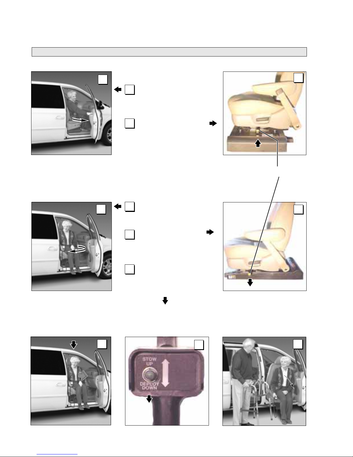
The Companion Seat provides
aid for those who have difficulty
entering or exiting Ford Windstar
Minivans using the OEM (original)
passenger’s seat. The Compan-
ion Seat utilizes your van’s
original passenger seat mounted
on an electric actuator powered
seat base.
The seat base conveniently
extends the seat automatically
out of the vehicle and lowers the
seat cushion to an easy load and
unload position. The seat base
then raises and retracts the seat
and occupant automatically into
the vehicle.
The seat-equipped STOW/
DEPLOY switch controls seat
extending and retracting func-
tions. The seat passenger and/or
assistant must manually open
and close the vehicle door and
manually rotate the seat. It is the
responsibility of the passenger to
engage and disengage the
vehicle-equipped passenger’s
seat belt as instructed by the
vehicle manufacturer.
Always engage the vehicle
parking brake and engage the
vehicle transmission in “Park”
before operating the Companion
Seat. Be certain the passenger
door is fully open before operat-
ing the seat. Visually inspect the
seat before operation. Do not
operate the seat if you suspect
damage, wear or any abnormal
condition.
Read and become familiar with all
seat operation safety precautions,
seat pre-operation notes, seat
operating instructions and manual
operating instructions before
attempting seat operation proce-
dures. Contact The Braun
Corporation immediately if any of
this information is not understood.
Call 1-800-THE LIFT.
Seat Rotation Lever
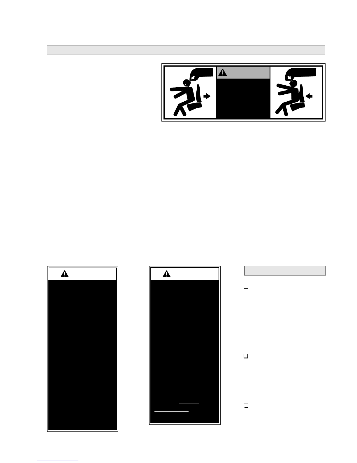
W
ARNING
Rotate and lock seat
in forward position
before operating
vehicle. Failure to do
so may result in
serious bodily injury
and/or property
damage.
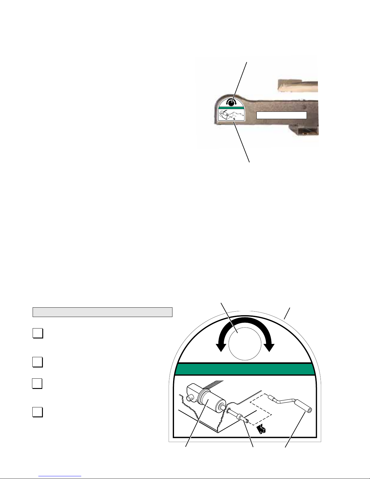
Seat Rotation
Ayellow-handled lever is located on the driver’s
side of the Companion Seat base. Simply lift the
lever to disengage the seat from the locked (en-
gaged) position and manually rotate the seat. The
spring-loaded seat rotation lever engages (locks)
when the seat is rotated fully outward (seat faces
doorway) or rotated fully inward (seat faces for-
ward).
Rotate and lock seat in forward position before
operating vehicle. Push the yellow-handled
lever down to ensure the lever is engaged (seat
is locked). Always test the seat to be certain the
seat rotation lever is in the engaged position.
Note: The passenger must lift and rotate his or her
feet when rotating the seat.
Note: The seat must be manually rotated fully
outward to the locked position before the STOW/
DEPLOY control switch can be activated.
Lift lever to disengage seat from
the locked (engaged) position.