Grammer MSG45/421 Operating instructions

February 2020
Material No. 1 447 263
GRAMMER repair manual for seat MSG45/421
Page 1 of 1
TABLE OF CONTENTS
Foreword
1 Description
1.1 Safety information
1.2 Nameplate
2 Diagnostics
2.1 Component overview
2.2 Fault overview –Identifying potential faults
2.3 Troubleshooting –Locating the fault
3 Repair work
3.1 Removing/installing backrest cushion
3.2 Removing/installing seat cushion
3.3 Removing/installing left and right cover
3.4 Removing/installing back plate with backrest bearing completely
3.5 Removing/installing the bellows
3.6 Removing/installing lap belt and buckle
3.7 Removing/installing the seat length adjustment completely
3.8 Removing/installing seat switch with cable and switch actuation
3.9 Removing/installing the backrest adjustment completely
3.10 Removing/installing the linkage of the weight display
3.11 Removing/installing the end stop (buffer)

GRAMMER repair manual for seat MSG45/421 –February 2020
Material No. 1 447 263
Foreword
Page 1 of 2
About this manual
This repair manual contains information and instructions for performing repair work
on the GRAMMER seat MSG45 with seat top 421.
The seat MSG45 with seat top 421 forms the basis of the illustration in the repair
manual. Any differences resulting from technical deviations in the work steps
(due to any seat design variations) are described in the text or in separate chapters.
All preparations to be made before starting work are listed at the beginning of each
chapter. These tasks are described in their own chapters and are carried out without
any of the preparations which may be listed there.
Within each chapter of this repair manual, all parts shown in the images are
numbered starting with "1". Each part is addressed within the chapter with the same
item number.
Only the item numbers in the valid spare parts catalogues can be used for spare
parts orders.
The work is described for the dismantled seat.
If the installation situation allows it, some work can also be carried out on an
installed seat.
For this reason, the surroundings of the installed seat must first be investigated for this
option before work is started. The safety specifications of the vehicle manufacturer
and those in Chapter 1 of this repair manual must always be complied with.
Any delivery variants requiring an explanation are also described in this repair
manual. Since the scope of delivery is based on the customer's order, certain
descriptions and illustrations of the seat fittings can differ.
The repair work is presented based on the seat for left-hand drive. The different
tasks must be carried out in a mirror image for repairs on vehicle designs with right-
hand drive.
If not otherwise indicated in the text, the directional information "front, back" and
"right, left" refer to the installed seat and the vehicle's direction of travel.
The layout has been developed in a way that makes it possible to later offer the
repair manual in the form of a CD-ROM/INTERNET/INTRANET.
General information on the seat!
Please contact the manufacturer about any assembly work required for the removal
and installation of the seat in the vehicle.
The seat has long-term lubrication (around 10 years). The lubrication points may
only be regreased with lubrication grease KFHC2N-50 DIN 51825 following repair
work on the points marked by (F) in the repair manual.
It is possible that not all fasteners are mentioned in this repair manual. It may be
necessary upon completion of the repair work that fasteners be inspected with
regard to their factory installation and their hold and tightness, and corrected
accordingly if needed.

GRAMMER repair manual for seat MSG45/421 –February 2020
Material No. 1 447 263
Foreword
Page 2 of 2
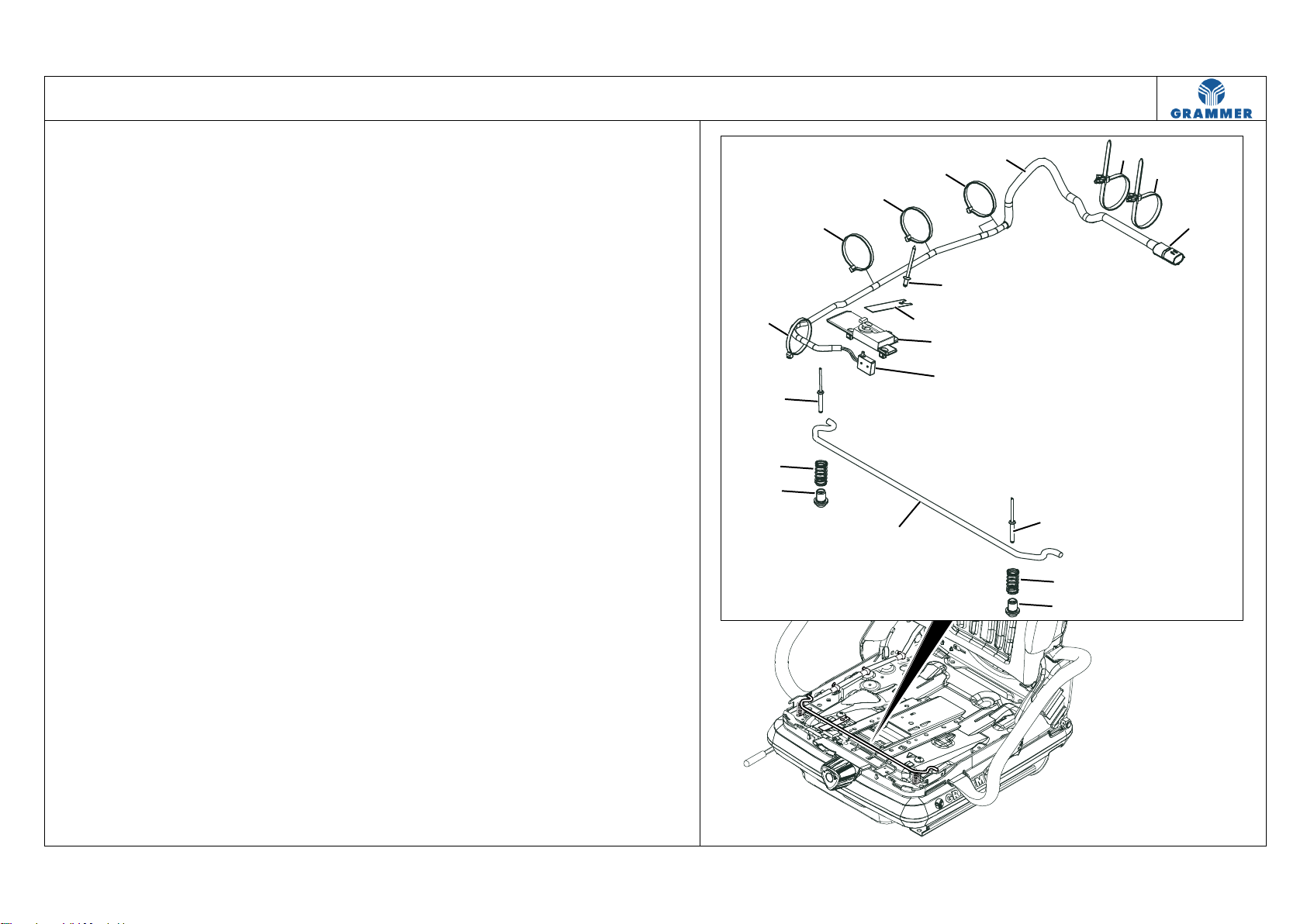
Bowden cables, cables, and hoses may only be secured by hand (therefore loose)
using cable ties in the specified locations. You must ensure that the Bowden cables,
cables and hoses are not pinched when adjusting the seat vertically and horizontally,
and that they follow the movement of the seat without causing tension.
All removed used parts must be replaced by the new parts supplied.
If no corresponding new part is included in the spare parts scope of delivery for
existing old parts, then they must be cleaned and inspected for further use.
The defective parts and wear parts must be replaced.
GRAMMER AG will reject any warranty claims if damaged or worn parts and
assemblies are not replaced by spare parts approved by GRAMMER.
Qualified personnel
The instructions represent the basis for proper and professional repair. The content of
the described work steps builds on the training status of a technician with a completed
vocational education and good knowledge of the product. This level of knowledge is
essential for performing the work described.
All information and instructions, especially the safety information in Chapter 1,
must be carefully read and followed completely, in order to prevent physical injury,
impairment of the operational safety of the seat, or damage to the seat as a result of
improper work.
It is ultimately impossible for GRAMMER AG to evaluate all situations which could
pose a risk of injury to the person involved. It is therefore absolutely necessary that
everyone performing repair work on the seat apply their expert knowledge to ensure
that their own safety is not jeopardised and that the seat is not negatively impacted
by the type of repair work selected, especially in regards to safety.
For these reasons, no liability can be assumed for such damage.
We also point out explicitly that all of the work steps described must only be carried
out in compliance with all directives and requirements of the responsible authorities
and of the health, accident and environmental protection regulations.
Right of modification and copyright
These seats are constantly being further developed. Please understand that we
must reserve the right to make changes to its form, equipment, and technology.
For these reasons, no claims can be derived from the content of this repair manual.
Reprinting, translation and reproduction, even as excerpts without our written
consent are prohibited.
GRAMMER AG PO box 14 54
D-92204 Amberg, Germany
Telephone +49 (0) 96 21 / 66-6822
www.grammer.com
Supplier and factory address:
GRAMMER AG
Köferinger Str. 9-13
D-92245 Kümmersbruck

GRAMMER repair manual for seat MSG45/421 –February 2020
Material No. 1 447 263
1 Description
Page 1 of 1
TABLE OF CONTENTS
1.1 Safety Instructions
1.2 Nameplate
Note:
Please refer to the currently valid seat operating manual for additional descriptions.

GRAMMER repair manual for seat MSG45/421 –February 2020
Material No. 1 447 263
1.1 Safety information
Page 1 of 1
1 Inspection and repair work may only be performed by specially trained personnel.
2 All of the work steps described must only be carried out in compliance with all
directives and requirements of the responsible authorities and of the health,
accident and environmental protection regulations.
3 Special instructions in the repair manual are highlighted as follows:
CAUTION…
indicates a possible danger to persons and how to avoid it.
ATTENTION ...
indicates possible material damage or destruction and how to avoid it.
Note: …
indicates an additional explanation for understanding the work to be performed.
Installation instruction: ...
indicates an additional explanation for understanding the installation work to be
performed.
4 The following steps must be carried out before starting any repair work:
Disconnect the seat from the power supply.
In the lower position, move the seat until it meets the end stops.
5 When handling oils, greases and other chemical substances, the product safety
requirements must be observed.

GRAMMER repair manual for seat MSG45/421 –February 2020
Material No. 1 447 263
1.2 Nameplate
Page 1 of 1
The nameplate is mounted on the rear left
of the back plate.
The nameplate includes the following data
(for example):
(A) Country of manufacture = MADE IN
XXXXXXX
(B) NAME = MSG45/421
(C) MATERIAL –NO. = 1319189
(D) Year / CW / assembly group
18 10 141:
Year of construction = 18 (2018)
Constructed in week = 10 (March)
Assembly group = 141
(E) ORDER NO. = XX
133448970001
Country code = XX
Note:
The correct MATERIAL NO. (C) on the
nameplate must always be specified when
placing orders.

GRAMMER repair manual for seat MSG45/421 –February 2020
Material No. 1 447 263
2 Diagnostics
Page 1 of 1
TABLE OF CONTENTS
2.1 Component overview
●Seat switch installation overview
●Seat switch and pin assignment with circuit diagram
2.2 Fault overview –Identifying potential faults which may occur
2.3 Troubleshooting –Locating the fault
1 Checking the seat switch

GRAMMER repair manual for seat MSG45/421 –February 2020
Material No. 1 447 263
2.1 Component overview
Page 1 of 2
Seat switch installation overview
(1) Seat switch cable harness
(2) Cable tie with plug-in anchor
(3) On-board power supply connector
(4) Blind rivet
(5) Pressure spring
(6) Bushing
(7) Switch bracket
(8) Cable ties
(9) Seat switch
(10) Cover
(11) Switch plate
(12) Blind rivet
3507
1
11
3
74
22
5
6
5
6
4
10
9
12
8
8
8
8

GRAMMER repair manual for seat MSG45/421 –February 2020
Material No. 1 447 263
2.1 Component overview
Page 2 of 2
Seat switch and pin assignment with
circuit diagram
(1) Seat switch cable harness
(3) On-board power supply connector
(9) Seat switch
(13) Seat switch lifter
(14) Assignment as normally open
contact (Z)
(Pin: P1 and P2)
(X) Line end. The line is not laid up to
the on-board power supply
connector (3).
(Z) The seat switch (9) is closed when
the seat is compressed.
The vehicle can be put into
operation.
Note:
Distance (A) between the rest position
and switching point of the seat switch
lifter (13) = 1,2 mm.
3508
Z
A
X
1
13
3
9
P1
P2
3
P1P2
P1 P2
14

GRAMMER repair manual for seat MSG45/421 –February 2020
Material No. 1 447 263
2.2 Fault overview –Identifying potential faults
Page 1 of 1
This Chapter contains information about faults which may occur in the seat. This information should serve to resolve the fault, with the help of Chapter 2.3 "Troubleshooting –
Locating the fault".
Faults caused by lack of maintenance or incorrect repairs are not taken into account.
Note: The relevant components are listed in Chapter 2.1 and the components to operate the functions are listed in the current seat repair manual, unless otherwise stated in the text.
Fault description
Possible cause
Eliminating the fault
The seat switch does not make contact when the seat cushion
is compressed.
The switch bracket has come loose from the spring
assembly.
The switch bracket is not resting on the pressure
springs.
The pressure springs have come loose from the
bushings.
Insert the switch bracket in the spring assembly
(see Chapter 3.8).
Place the switch bracket on the pressure springs
(see Chapter 3.8).
Insert the pressure springs in the bushings
(see Chapter 3.8).
Bellows are trapped between the seat cushion and
spring assembly.
Seat switch lifter is defective.
The spring sheet broken or bent.
Run your hand between the bellows and seat
cushion to release the tension. Remove/install the
seat cushion if necessary (Chap. 3.2).
Replace the seat switch with cable (see Chapter 3.8).
Replace the seat switch with cable and switch
actuation (Chap. 3.8).
Seat switch is not functioning.
Vehicle power supply or electronics are defective.
Plug connection (on-board power supply connector
of seat - vehicle) is defective.
Seat switch is defective.
Check the electrical system of the vehicle.
Check the plug connection, remake if necessary.
Check the seat switch (Chap. 2.3, Test step 1.1),
completely replace the seat switch if necessary
(see Chapter 3.8).

GRAMMER repair manual for seat MSG45/421 –February 2020
Material No. 1 447 263
2.3 Troubleshooting –Locating the fault
Page 1 of 1
1 Checking the seat switch
Prerequisites for troubleshooting:
Electrical system of the vehicle has been checked and is in order.
Overview of the relevant components, see Chap. 2.1.
Test
step
Test/operate
Result/objective
Fault elimination
1.1
•Disconnect the plug connection (on-board power supply
connector (3) of seat - vehicle).
•Measure the resistance at Pins P1 and P2:
Measurement note: Seat switch is open.
P1 ΩP2
>> 0.7 Ω ()
Continue with test step 1.2.
<< 0.7 Ω (0)(short circuit)
Replace the seat switch with cable
(see Chapter 3.8).
1.2
•Compress the seat cushion and measure the resistance at Pins
P1 and P2:
Measurement note: Seat switch is closed.
P1 ΩP2
= 0.7 Ω (20%)
End of test.
>> 0.7 Ω ()(interruption) or
<< 0.7 Ω (0)(short circuit)
Replace the seat switch with cable (see
Chapter 3.8).

GRAMMER repair manual for seat MSG45/421 –February 2020
Material No. 1 447 263
3 Repair work
Page 1 of 1
TABLE OF CONTENTS
3.1 Removing/installing backrest cushion
3.2 Removing/installing seat cushion
3.3 Removing/installing left and right cover
3.4 Removing/installing back plate with backrest bearing completely
3.5 Removing/installing the bellows
3.6 Removing/installing lap belt and buckle
3.7 Removing/installing the seat length adjustment completely
3.8 Removing/installing seat switch with cable and switch actuation
3.9 Removing/installing the backrest adjustment completely
3.10 Removing/installing the linkage of the weight display
3.11 Removing/installing the end stop (buffer)

GRAMMER repair manual for seat MSG45/421 –February 2020
Material No. 1 447 263
3.1 Removing/installing backrest cushion
Page 1 of 1
Removal, installation
1 Open the document box.
2 Unscrew the seven cup head screws (3).
Installation instruction:
Cup head screw (3), 3.5 ± 0.5 Nm.
3CAUTION danger of injury
caused by the back plate (2) jerking
forward!
If the backrest cushion (1) has been
removed, the back plate (2) must be
supported when activating the handle
for backrest angle adjustment.
4 Remove the backrest cushion (1) from
the back plate (2).
5 Installation is carried out in reverse
order.
3505
3
3
3
2
1
3
3

GRAMMER repair manual for seat MSG45/421 –February 2020
Material No. 1 447 263
3.2 Removing/installing seat cushion
Page 1 of 1
Removal
1 Engage the backrest (3) in the
foremost position.
2 Unhook the seat cushion (1) from the
spring assembly (5). To do this, first
pull the snap lock grip (2) backwards
and then upwards.
3 Grasp the seat cushion (1) with both
hands at the front left and right, press
downwards and remove by pulling it
out forwards.
Installation
1 Place the seat cushion (1) on the spring
assembly (5). The two holders (6) at the
bottom of the seat cushion (1) must be
level with the hooks (4) on the spring
assembly (5).
Note:
If a seat switch is provided, ensure that
the pressure springs and the switch
bracket are correctly seated when
installing the seat cushion (1) to
guarantee the proper functioning of the
seat switch (see Chapter 3.8).
2 Press the seat cushion (1) down at the
front left and right and push it
backwards onto the two hooks (4) with
the two holders (6).
3 Press down on the seat cushion (1) at
the rear centre until the snap lock grip
(2) engages.
Note:
Check the function of the seat switch:
Press the front of the seat cushion (1)
several times at the left and right to
check whether the seat switch makes
audible contact (see Chapter 3.8).
3506
1
4
2
1
1
3
4
6
5

GRAMMER repair manual for seat MSG45/421 –February 2020
Material No. 1 447 263
3.3 Removing/installing left and right cover
Page 1 of 1
Removal, installation
1 Remove the seat cushion (Chap. 3.2).
2 Remove the lap belt and buckle
(Chap. 3.6).
3 Unclip two front (2) and rear (3) snap-in
hooks on the right-hand cover (1) from
the indents (6 and 4) on the right-hand
backrest holder (5) and remove the
cover (1).
4 Unclip two front (9) and rear (10) snap-
in hooks on the left-hand cover (8) from
the indents (13 and 11) on the left-
hand backrest holder (12) and remove
the cover (8).
5 Replacing the right cover (1) or left
cover (8):
Break out the predetermined
perforated breaking points (A, B) for
the holders (7) and the lap belt and
buckle on the cover (1, 8) as required.
6 Installation is carried out in reverse
order.
3509
1
9
8
1
46
6
5
8
3
2
5
7
A
A
A
B
B
10
11
13
12
7

GRAMMER repair manual for seat MSG45/421 –February 2020
Material No. 1 447 263
3.4 Removing/installing back plate with backrest bearing completely
Page 1 of 2
Removal, installation
1 Remove the backrest cushion
(Chap. 3.1).
2 Remove the seat cushion (Chap. 3.2).
3 Remove the lap belt and buckle
(Chap. 3.6).
4 Remove the right-hand and left-hand
cover (Chap. 3.3).
5 Unscrew the right-hand and left-hand
flange nut (2).
Installation instruction:
Flange nuts (2), 25 ± 5 Nm.
6 Unscrew the right-hand and left-hand
socket head screw (4) and remove the
right-hand (1) and left-hand holder (3)
from the seat.
Installation instruction:
Socket head screws (4), 25 ± 5 Nm.
3511
1
3
4
2
2
4

GRAMMER repair manual for seat MSG45/421 –February 2020
Material No. 1 447 263
3.4 Removing/installing back plate with backrest bearing completely
Page 2 of 2
7 Fold the back plate (1) completely
forwards to release the return spring (6).
8 Unscrew two flange bolts (3) and
remove the flange nuts (5).
Installation instruction:
Flange nuts (5), 25 Nm.
9 Support the backrest plate (1) and
press two bushings (2) inwards out of
the left-hand (4) and right-hand (7)
backrest holder.
Installation instruction:
When attaching the back plate (1),
make sure that the cam (arrow) is
above the hook of the return spring (6).
10 Unhook the backrest plate (1)
upwards, remove the bushings (2) and
return spring (6).
Installation instructions:
● Grease the entire circumference (F)
of the bushings (2) and the outer
surfaces (F) of the return spring (6).
● Place the return spring (6) on the
three punched lugs on the backrest
holder (7). The hook of the return
spring (6) must point backwards.
11 Installation is carried out in reverse
order.
3510
6
1
4
5
5332
7
2
6
53
6
7
F
FF
1

GRAMMER repair manual for seat MSG45/421 –February 2020
Material No. 1 447 263
3.5 Removing/installing the bellows
Page 1 of 1
Removal, installation
1 Remove the seat cushion (Chap. 3.2).
2 Remove the lap belt and buckle
(Chap. 3.6).
3 Remove the cover (Chap. 3.3) on the
right and left.
4 Remove the right-hand and left-hand
holder (see Chapter 3.4).
CAUTION Damage!
Do not tear off the mushroom knobs (4)
during removal.
Stretch the mushroom knobs
somewhat lengthwise and use two
screwdrivers to lift them out on the
thicker end (arrow).
Installation instructions:
Insert the mandrel (Ø approx. 3 mm)
into the mushroom knob (4) through
the outside opening provided for this
purpose (1) and carefully draw the
bellows (1) against the mandrel.
Press the mushroom knob (4)
stretched in this way into the
corresponding hole.
5 Removing the bellows (1) from the
upper suspension component:
Lever out 2 mushroom knobs (4).
Unhook 6 keyhole knobs (2 and 3).
Unhook 2 bellows brackets (5) from
the rear hooks.
Unhook 6 bellows cut-outs (8) from
the front six hooks.
Pull out 2 cable ties with a plug-in
anchor (6) from the upper suspension
component and bellows (1).
6 Removing the bellows (1) from the
lower suspension component:
Unhook 5 keyhole knobs (7).
7 Pull the bellows (1) down over the
lower suspension component and
remove.
8 Installation is carried out in reverse
order.
3512
4
1
53
3
2
3
2
5
7
7
8
8
4
4
6

GRAMMER repair manual for seat MSG45/421 –February 2020
Material No. 1 447 263
3.6 Removing/installing lap belt and buckle
Page 1 of 1
Removal, installation
1 Remove the seat cushion (Chap. 3.2).
2 Unscrew the hexagon nut (2).
Installation instruction:
Hexagon nut (2), 50 Nm.
3 Pull the buckle (1) and short (3) and long
(4) bushings off the hexagon bolt (5).
4 Unscrew the hexagon nut (9).
Installation instruction:
Hexagon nut (9), 50 Nm.
5 Pull the lap belt (10) and short (8) and
long (7) bushings off the hexagon
bolt (6).
6 Remove two hexagon head bolts
(5 and 6).
7 Installation is carried out in reverse
order.
3513
46
2
1
9
3
5
78
10

GRAMMER repair manual for seat MSG45/421 –February 2020
Material No. 1 447 263
3.7 Removing/installing the seat length adjustment completely
Page 1 of 1
Removal, installation
1 Unhook the bellows from the lower
suspension component (1), push
upwards and fix (see Chapter 3.5).
2 Pull the snap-on rail (7) and rail (5) off
the adjusting rail (4) and completely
remove the adjusting rail (9).
Note:
Push the handle for fore/aft adjustment
(8) to the right to disengage the snap-
on rail (7) completely from the
adjusting rail (9).
Installation instruction:
Grease the rail running surfaces (F).
3 Mark the complete installation position
of the adjusting rail (4) and adjusting
rail (9).
4 Unscrew four socket head screws (2)
and completely remove the flange nuts
(6), spacers (3) with adjusting rail (4)
and adjusting rail (9).
Installation instructions:
● Completely install adjusting rail (4)
and adjusting rail (9) according to the
marking.
● Socket head screws (2), 25 Nm.
5 Installation is carried out in reverse
order.
3514
8
2
1
4
F
F
2
2
2
3
3
3
3
6
5
6
6
6
7
9
Other manuals for MSG45/421
1
Table of contents
Other Grammer Car Seat manuals

Grammer
Grammer ACTIMO M User manual

Grammer
Grammer MSG95 User manual

Grammer
Grammer PRIMO M User manual

Grammer
Grammer LINEA User manual

Grammer
Grammer KINGMAN User manual

Grammer
Grammer MSG 90.6PG Operating instructions

Grammer
Grammer PRIMO XL User manual

Grammer
Grammer MSG75G User manual

Grammer
Grammer PRIMO XL Plus User manual

Grammer
Grammer MSG65 User manual