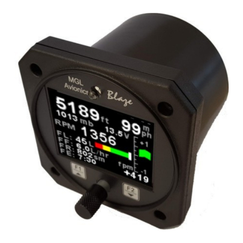
Brauniger ALPHAMFD Specification sheet

Operating and
Installation Manual
Hardware Rev 401, Software Ver 4.04 24.11.2007
Technical specifications subject to change without notice!
This operating manual must be given to customer with every ALPHA
ALPHAALPHA
ALPHAMFD
purchase!
BRÄUNIGER Flugelectronic GmbH
Dr. Karl Slevogt Str. 5 D-82362 Weilheim / Germany
Ph +49-881-64750, Fax +49-881-4561

2
1
Introduction ......................................................................... 4
2
Mounting and Connections................................................... 5
2.1
Warning ................................................................................................... 5
2.2
Mounting into Cockpit................................................................................ 5
2.3
Electrical Connections................................................................................ 6
2.3.1
Switch-Off unuse Temperature Ports................................................... 7
2.3.2
Connection Plan
ALPHA
MFD (Har ware Rev 401) ................................ 9
2.3.3
Connection Boar (Har ware Rev 401).................................................10
2.4
Mounting Fuel Flow Sen er .......................................................................10
2.4.1
General Notes....................................................................................10
2.4.2
Important Safety Notes.......................................................................11
2.4.3
Important Information to Achieve Precision Measurements ....................11
2.4.4
Drawing: Fuel Flow Sen er Mounting...................................................12
2.5
Pitot Tube an Static Port .........................................................................13
2.5.1
Static Port .........................................................................................13
2.5.2
Pitot Port...........................................................................................13
3
Power On and Built-In Self-Test BIT)............................... 13
4
Flight Management ............................................................ 13
4.1
Air Spee In icator (IAS, CAS) ..................................................................13
4.1.1
Calibration of Air Spee (CAS) .............................................................14
4.1.2
Spee In ication “Stretching Schemes” / Units Air Spee .......................14
4.1.3
Stall-Alarm.........................................................................................15
4.1.4 Vne-Alarm...........................................................................................15
4.2
Altimeter an Air Pressure.........................................................................16
4.2.1
Altitu e MSL (QNH) ............................................................................16
4.2.2
Altitu e above GND / AGL (QFE)..........................................................16
4.2.3
Flight Level (FL, QNE).........................................................................16
4.3
Altitu e Gui ance Mo e (AGM)..................................................................16
4.4
VSI (Vertical Spee In icator) ...................................................................17
4.4.1
Single Pointer Display .........................................................................17
4.4.2
Sector Display....................................................................................18
4.4.3 Variometer-Acoustic..............................................................................17
4.5
Flight Time, Take-Off Time an Date of Flight.............................................18
4.6
Temperature an Voltmeter ......................................................................18
4.7
Real-Time................................................................................................19
5
Engine Management........................................................... 19
5.1
Engine RPM .............................................................................................19
5.1.1
RPM Measurement RPM Port ...............................................................19
5.1.2
Capacitive RPM Measurement at ignition cable not available for
Hardware Rev 401) ....................................................................................20
5.2
Engine Hour Meter ...................................................................................20
5.3
Fuel State an Fuel Flow (Consumption) ....................................................20
5.3.1
Important Safety Information..............................................................20
5.3.2
Fuel Flow Meter .................................................................................21
5.3.3
Precision of Fuel Flow.........................................................................22
5.3.4
Fuel Flow with Engines with Fuel Flow-Back System..............................22
5.3.5
Measuring with two flow sen ers (engines with fuel flow back system)..22
5.3.6
Recommended: Measuring with one fuel flow sen er (engines with fuel
flow back system) ..........................................................................................22
5.3.7
Display of Fuel Flow ...........................................................................23

3
5.3.8
Calibration of Fuel Flow Meter .............................................................23
5.3.9
Display of Fuel State...........................................................................24
5.3.10
How to enter the Actual Fuel State after filling up ..............................24
5.4
Cylin er Hea Temperature (CHT) an Exhaust Gas Temperature (EGT).......24
5.5
Water Temperature..................................................................................25
5.6
Oil Temperature.......................................................................................25
5.7
Display of Temperatures...........................................................................26
5.8
Oil Pressure an Low Oil Pressure Warning.................................................26
5.8.1
Oil Pressure Switch.............................................................................26
5.8.2
Analogue Oil Pressure Sen er..............................................................27
5.9
Voltmeter ................................................................................................28
5.10
Back-Up Power Supply...........................................................................28
6
Flight Data Recorder .......................................................... 29
6.1
MEMO-Mo e ............................................................................................29
7
Other Functions.................................................................. 30
7.1
Acoustic an Optical Warnings...................................................................30
7.1.1
Stall-Alarm an Vne-Alarm ..................................................................30
7.1.2
Low Voltage.......................................................................................30
7.1.3
Low Fuel ...........................................................................................30
7.1.4
Cable Breakage of Temperature Sen ers..............................................30
7.1.5
Engine Temperatures too high.............................................................31
7.1.6
Altitu e Gui ance Mo e ......................................................................31
7.1.7
Oil Pressure too low or too high...........................................................31
7.1.8
RPM too high .....................................................................................31
7.1.9
ERORR-Messages uring Power on Self-Test (BIT)................................31
7.1.10
List of ERROR-Co es .......................................................................32
7.2
Theft prevention an Passwor .................................................................33
7.2.1
Passwor Function "Off" .....................................................................33
7.2.2
Passwor -Function "Car Ra io"............................................................33
7.2.3
Passwor Function "Maximum"............................................................33
7.3
Selection of Units .....................................................................................34
7.4
Software Up ate ......................................................................................34
8
SET-Mode ........................................................................... 34
8.1
Restore Factory Settings ...........................................................................35
8.2
SET-Mo e Settings ...................................................................................35
9
Information for certain Engines......................................... 37
9.1
Rotax 582................................................................................................37
9.2
Rotax 912/912 S/914................................................................................37
9.3
Rotax 503................................................................................................37
9.4
Notes on using the ALPHAMFD on flex-wing Ultralights.............................38
10
Periodical Check................................................................. 38
11
Technical Data ………………………………………………………41
Backlight function
……..…………………………………………………………….41
12
Warranty ............................................................................ 41

4
1 Introduction
With it's innovative i eas an mo ern technology the ALPHAMFD offers a complete
system for flight an engine-management for ultralight/microlight pilots. Important
information for navigation an engine control are easily rea able, presente on an
integrate Liqui Crystal Display.
The ALPHAMFD was carefully esigne to be extremely reliable, safe an
maintenance free. A self-test on power-on, etection an warning of faulty sen ers
an the au io alarm through the Intercom make the ALPHAMFD an extremely
reliable an safe flight information system.
Using mo ern processors an a flash-memory, the software of the ALPHAMFD can
be up ate any time an thus being up ate to the latest software version without
hassle an cost. The ALPHAMFD is a soun long-term investment.
In or er to avoi information overloa of the pilot, only the most important information
like spee , vario, altitu e, RPM, EGT, CHT or water/oil-temperature, flight time, real-
time, fuel state an consumption, are permanently isplaye . More information can be
calle up by pressing only a few keys, e.g. flight log or engine hours, etc.
The innovative LC- isplay is easy to rea in any light con itions, all rea -outs are
esigne following ergonomic rules.
Because of the logical an clearly structure menus, the ALPHAMFD is very easy to
operate. You basically only have to switch on the instrument an off you go. However
we strongly recommen you rea the operation manual carefully to make the best out
of the many functions the ALPHAMFD offers.
We wish you many fantastic an safe flights with your new ALPHAMFD.
Note:
The operating instructions contain many important information which are necessary for
a safe operation of the ALPHA
ALPHAALPHA
ALPHAMFD. Please rea the instructions carefully! If you o
not un erstan something, you must not use the ALPHA
ALPHAALPHA
ALPHAMFD. If you have questions,
please contact the nearest
BRÄUNIGER
Service Centre or
BRÄUNIGER
irectly.
WARNING! This icon esignates important safety information in the
operating manual. Please rea carefully!

5
2 Mounting and Connections
2.1 Warning
The ALPHA
ALPHAALPHA
ALPHAMFD is not certifie by LBA/FAA/JAA as this is not require for Ultralights
in most countries. However, if such a certification will be require in the future, the
certification will be complete . The instrument is esigne following the most state of
the art technologies an it is extensively teste following the proce ures of LBA!
Although the ALPHA
ALPHAALPHA
ALPHAMFD is an electronic an very precise instrument, incorrect
values can be shown, mistakes in operation can be ma e an shown values can be
misinterprete . By operating the ALPHA
ALPHAALPHA
ALPHAMFD, the user confirms that he knows about
these angers an he is accepting responsibility for any possible risks.
In or er to minimize these risks, the operating instructions MUST be rea carefully. If
you have questions, please contact
BRÄUNIGER
or a
BRÄUNIGER
Service Centre.
2.2 Mounting into Cockpit
It is very easy to mount the ALPHAMFD in your cockpit. You only nee a little skill,
no special tools are require .
Dimensions of ALPHAMFD:
Front 220 x 145 mm
Cockpit Cut-out 137 x 194 mm
Drillings 207 x 87 mm, 32 mm from
bottom an 26 from the top.
All measurements in mm
Total weight only approx. 850 grs!
Inclu ing Backup battery
220
14587
125
Screws M4 Cylin er hea

6
WARNING:
The following points must be carefully observed:
• Protect the unit from too high or too low temperatures. The unit works reliably in
a temperature range of -15°C to 50° Ceslsius.
• Protect the unit from excessive shock or vibrations. It might be necessary to
mount the unit with suitable shock absorbing materials.
• Protect the unit from irt an moisture an all kin s of oils an gasoline.
• The isplay must be easy to rea , protect the unit from glare an ensure a goo
fiel of view.
• Mount instrument as far away from ra io / transpon er antennae as possible.
All points must be observed for longevity and reliability!
2.3 Electrical Connections
If you have never before installe electrical instruments an you are not exactly sure
what to o, please ask someone who has experience to help you with the installation.
When working with sen ers, please han le carefully, as they are sensitive electronic
parts.
Only use high-quality cables (highly flexible, stran e an shiel e ) an connectors.
Check that your cables run untangle an clean. Disconnect the aircraft battery before
working on electrical components!
Ni-Cr-Ni temperature sen ers require special cables which are supplie with the
sen ers!
WARNING:
All wires shoul be protecte by small metal terminals to ensure a
lasting an safe connection to the ALPHAMFD. All cables an the Pitot tube
shoul be secure against pull. There is a special mounting bracket on the rear
of the ALPHA
ALPHAALPHA
ALPHAMFD for securing against pull.

7
When mounting the senders the following points must be observed:
• Protect the sen er lea s against high temperatures.
• Protect the sen er lea s from excessive vibration. However, a certain amount of
movement must be allowe .
• The sen er lea s must not be sharply bent or abra e .
• The threa s of EGT, CHT, water- an oil temp sen ers must be treate with
Loctite Anti Seize (or a similar agent) to ensure trouble-free unscrewing.
Type K temperature senders NiCrNi) MUST be exten e with specially
compensate extension lea s. If the lea s of the sen ers are too short an must be
exten e , the special Type K extension lea s an Type K plug an sockets MUST be
use . These lea s are available from
BRÄUNIGER
:
Type Pt100 temperature senders o not nee specially compensate extension
lea s but can be exten e with stan ar copper lea s.
Please observe, that the ALPHA
ALPHAALPHA
ALPHAMFD is equipped with two different types of
temperature ports: Type K and Pt100. These ports can ONLY be used with
the respective type of sender.
Please follow the technical information of the sen ers you are using.
NOTE:
BRÄUNIGER
provi es complete cable looms an sen er kits as an option for
some popular engines. With these connection kits, it is even easier to connect the
ALPHAMFD.
2.3.1 Switch-Off unuse Temperature Ports
The ALPHA
ALPHAALPHA
ALPHAMFD has six ifferent ports where temperature sen ers can be connecte
(Two Type Pt100 an four Type K). Because with some engine configurations some
ports are not use , they can be switche off.
Because of their technical characteristics, temperature ports still show temperatures
even when no sen ers are attache , an these temperatures are of course "nonsense".
Therefore the ports can be switche off an "nonsense" values are suppresse .

8
Switching-off ports is one in SET-Mo es 31 through 37.
SET Mo e
Number
Temperature or fuel
Ports
Display Text Options
31 Pt100 WaterTemp Use Water Temp Port YES / NO
32 Pt 100 Oil temp Use Oil Temp Port YES / NO
33 EGT 1 Use EGT 1 Port YES / NO
34 EGT 2 Use EGT 2 Port YES / NO
35 CHT 1 Use CHT 1 Port YES / NO
36 CHT 2 Use CHT 2 Port YES / NO
37 Fuel flow Use Fuel Port YES / NO
Attention: Under set mode 37 it’s up from version 4.04 possible to
deactivate the fuel port. This may be helpful for trikes where the gas tank is
visible close to the pilot, or fuel systems with high flow back systems where
the flow sensor can’t work!
Note: The factory setting is all temperature ports ON!
WARNING: Make sure only unused temperature ports are switche
off! If a
use temperature port with a connecte sen er is acci entally switche off,
the temperature is not displayed and also the alarm function is
inoperative!

9
2.3.2 Connection Plan ALPHA
MFD
(Har ware Rev 401)
Sen ers
on engine
Cable
Connection ALPHA
ALPHAALPHA
ALPHAMFD
Water Temp
Pt100
Water (+) Pt100
Oil Temp
Pt100
Oil Temp (+) Pt100
Oil/Water (-)
(common for Pt100 and flow)
Flow Meter
to engine
+ 12 V OUT
Flow to engine, Signal
Flow Meter
back to tank
Flow to tank, Signal
Oil Pressure
Oil Pressure
RPM
(Rotax)
RPM
Aircraft
Battery
+ Batt Power
Supply
7...24 V
Ground
Thermocouple
Type K
(NiCrNi)
Ground case (screw)
EGT 1
Type K
EGT 1 (+)
EGT 1 (-)
EGT 2
Type K
EGT 2 (+)
EGT 2 (-)
CHT 1/EGT 3
(Water 912)
Type K
CHT 1 (+)
C
HT 1 (
-
)
CHT 2/EGT 4
(Water 912)
Type K
CHT 2 (+)
CHT 2 (
-
)
Intercom Diode
Plug
Sound (+)
Sound (-)
white
6
4
9
5
7
1
10
8
2
5
Type K Plug & Sockets
1.1.1.1.1.1
Type
re
white
white
green
brown
white
white
green
brown
or contact
black
green
white
green
white
white
white
green
green
+
+
+
+
-
-
-
-
green
green
green
green
white
white
white
white
Shiel
6
7
8
9
10
11
12
16
15
11
4
1
2
3
19
20
17
18
blue
yellow
white
green
violet
brown
grey/pink
grey
black
+
+
re
3
re
13
14
Re /blue
re

2.3.3 Connection Boar (Har ware Rev 401)
1
+
12V Out FLOW
1
12 V Power for Fuel Flow Sen ers 1 an 2
2
+
FLOW to engine
2
Fuel Flow Sen er 1 from tank to engine
3
+
FLOW to tank
3
Fuel Flow Sen er 2 from engine back to tank
4
-
GND Pt100/Flow
4
Common Groun for both Fuel Flow Sen ers an both Pt100
temperature sen ers
5
+
5
6
-
EGT 1 (Type K)
6
Exhaust Gas Temperature EGT 1 (Type K)
7
+
7
8
-
EGT 2 (Type K)
8
Exhaust Gas Temperature EGT 2 (Type K)
9
+
9
10
-
CHT 1 (Type K)
10
Cylin er Hea Temperature CHT 1 (Or Water 1 for Rotax 912) or
EGT 3 (Type K)
11
+
11
12
-
CHT 2 (Type K)
12
Cylin er Hea Temperature CHT 2 (Or Water 2 for Rotax 912) or
EGT 4 (Type K)
13
+
Water Temp (Pt100)
13
Water temperature (Type Pt100)
14
+
Oil Temp (Pt100)
14
Oil temperature (Type Pt100)
15
-
15
16
+
Intercom
16
Intercom connection for alarm soun s
17
+
BATT 7...28 V In
17
Main power supply from aircraft 7 to 28 Volts
18
-
BATT Gnd
18
Main aircraft groun
19
+
Oil Press
19
Oil pressure analog signal or switch
20
+
RPM Signal
20
RPM signal
Screw on ALPHA
ALPHAALPHA
ALPHAMFD case:
Groun for shiel of lea s
Backlight is connected to a separate 3 pin round DIN connector, pin 1 is
+12 Volt and pin 3 is ground.
Numbers are base on numbers of sticker on case an on connection plan.
Connection of lea s: Open cable cage clamps with suitable tool (screw river) an
insert lea s. Always use cable terminators!
2.4 Mounting Fuel Flow Sender
2.4.1 General Notes
The fuel capacity in icator of the ALPHA
ALPHAALPHA
ALPHAMFD works with a special fuel flow sen er.
We recommen only to use the sen er supplie by
BRÄUNIGER
, because other
sen ers are not a apte to the ALPHA
ALPHAALPHA
ALPHAMFD an precise function can not be
guarantee . The fuel flow sen ers transmits pluses accor ing to the actual fuel
consumption to the ALPHA
ALPHAALPHA
ALPHAMFD. These pulses are a e up to a fuel capacity
in icator. The sen er can be use with all kin s of fuel.

11
The
BRÄUNIGER
fuel flow sen er is loope in the fuel line between filter an engine.
Make sure all connections of fuel line are leak proof an secure. Secure all line
connections with suitable parts, e.g. hose clamps.
The fuel flow sen er is esigne in such a way, that even when the sensor wheel is
blocke , there is always enough fuel throughput to keep the engine running. Of course
the fuel flow can not be measure with a blocke sensor wheel.
2.4.2 Important Safety Notes
WARNING! To prevent air bubbles from getting stuck insi e the fuel flow
sen er, the sen er MUST be mounte in an angle of optimal 90° an
minimum 60° relative to the longitu inal axis of the aircraft. Only this way a
precise measurement can be achieve . The irection of the fuel flow MUST be
from bottom to top! Take care of the correct flow irection in icate by the
arrow on the sen er.
WARNING! The fuel flow sen er MUST be mounte AFTER the fuel filter so
that foreign matter in the fuel cannot block the sensor wheel!
WARNING! When mounting the fuel flow sen er you MUST observe the safety
an operation notes of the engine manufacturer!
2.4.3 Recommen ations to Achieve Precision Measurements
Because most fuel pumps create strong vibrations in the fuel line an these vibration
can negatively influence the precision of the fuel flow sen er, the sen er shoul be
mounte far away from the fuel pump.
The fuel flow sen er shoul be mounte close to the tank. The high temperatures in
the engine compartment can change the viscosity of the fuel which can negatively
influence measurement precision!

12
2.4.4 Drawing: Fuel Flow Sen er Mounting
Fuel Flow
Sen er
From
Tank
Fuel Filter
To engine
Min 60°
Optimal 90°
Fuel Flow Sen er Mounte on Rotax 912 S as escribe in Section 5.3.6

13
2.5 Pitot Tube and Static Port
There are 2 ifferent pressure ports on the backsi e of the case:
2.5.1 Static Port
This is the port for the static pressure. It must be connecte to the static port of the
aircraft. If you on't know where the static port of your aircraft is, ask the
manufacturer of the aircraft. A static pressure port is only necessary for aircraft with
close passenger cabin. Open flex-wing Ultralights can leave the static port open
without connecting it anywhere.
2.5.2 Pitot Port
This is the port for the pitot pressure. The pitot tube of the aircraft is connecte to the
pitot port. This is one with stan ar silicone hose. Check that the tube is neither
tangle nor sharply bent on its way from the pitot tube to the ALPHA
ALPHAALPHA
ALPHAMFD. The pitot
tube shoul be free of turbulences for precise measurements. The pitot shoul be
mounte parallel to the aero ynamic air flow uring cruise flight.
Because the i eal mounting of the pitot tube is ifferent for every aircraft type, please
contact your aircraft manufacturer for special information.
3 Power On and Built - In Self-Test (BIT)
By pressing the <ON/OFF>-key the instrument is switche on. For a short perio of
time all segments of the LC- isplay are illuminate in or er to test the function of the
isplay. Next the instrument goes into CHECK-Mo e. An internal self-test is execute
an all sen ers are checke for correct signals. If the ALPHAMFD iscovers a fault, it
isplays an ERROR-co e. A list of all possible ERROR-co es is liste in section 7.1.10 .
If everything is OK, you will see several "CHECK OK" messages an the instrument is
rea y for operation. Among others the spee range (which is set by the factory) is
isplaye . This is an a itional safety check for the pilot.
4 Flight Management
4.1 Air Speed Indicator (IAS, CAS)
The ALPHAMFD has an easy to rea large
analogue isplay of the air spee . By using a
stan ar Pitot tube the In icate Air Spee (IAS) is
isplaye . Note: IAS shows the spee in every
altitu e accor ing to the measure ynamic air
pressure. At high altitu es the actual True Air
Spee (TAS) is higher than the IAS. Displaying the
IAS has several a vantages an is also require by
various aviation authorities. For example the spee
never to excee (Vne) or the stall spee (Vso or
Vs1) can always be rea at the same spot of the

14
scale at every altitu e.
Stan ar , commercially available, Pitot tubes are use for spee -sen ers. The spee
in icator is calibrate by
BRÄUNIGER
accor ing to the correspon ing ynamic air
pressure.
4.1.1 Calibration of Air Spee (CAS)
The pilot can in ivi ually calibrate the spee in icator in SET-Mo e 15 by a justing the
SPEED GAIN factor. This way measurement errors, cause e.g. by a not optimal
position of the Pitot tube, can be in ivi ually correcte . After calibration, CAS
(Calibrate Air Spee ) is in icate . The efault value is >100<. If you a just the
SPEED GAIN e.g. to <110> the spee in ication will show a approx. 10% higher CAS.
The easiest way to calibrate the air spee in icator is to use a GPS. On a ay with no
win the Groun Spee is compare to the In icate Air Spee . You shoul fly your
entire spee range, i.e. lan ing spee , me ium spee , cruise spee an close to the
Vne. The ifferences in GS to IAS will probably vary through the spee range. It is
optimal to calibrate close to lan ing spee . It is also recommen e to fly ifferent
courses (e.g. 360°, 270°, 180° un 90°) to eliminate possible win influences.
A itionally the spee zero point can be calibrate . This is one in SET-Mo e 16
(SPEED ZERO).Press two times the “Enter” key.
.
WARNING!
The possibility to calibrate the Air Spee In icator allows for a very accurate
calibration of the Calibrate Air Spee . But if the calibration is done
incorrectly, the CAS in ication can show inaccurate speeds which can lead
to serious accidents landing!) Therefore Aircraft manufacturers can
block the settings for Speed calibration. Stall and Vne for the user.
It is also highly recommen e to calibrate the spee zero point every
2-3 months to preserve accuracy.
4.1.2 Spee In ication “Stretching Schemes” / Units Air Spee
The ALPHA
ALPHAALPHA
ALPHAMFD is available in 6 ifferent versions:
Version Speed-Units Speed-Range VSI Units
Version A Km/h 40 – 220 km/h m/s
Version B Km/h 60-340 km/h m/s
Version C Knots or mph 24 –130 kts ft/min
Version D Knots or mph 32 – 190 kts ft/min
Knots-versions can be converte to mph-versions. This must be one at the factory.
Km/h-versions can also be converte to kts or mph versions. Again this must be one
at
BRÄUNIGER
.

15
WARNING: To get a precise in ication of the air spee , some scales are
"stretche ". Please note the different resolutions of the scales. The
increment between two marks can in icate spee ifferences from 2.5 km/h to
10 km/h!
Example:
ALPHA
ALPHAALPHA
ALPHAMFD version B (340 km/h) uses the following "stretching scheme":
• From 60 km/h to 110 km/h every mark in icates a spee resolution of 2,5 km/h
(important for precise in ication of spee for lan ing or to prevent stalling)
• From 110 km/h to 210 km/h every mark in icates a spee resolution of 5 km/h
• From 210 km/h to 340 km/h every mark in icates a spee resolution of 10 km/h
A itional etails in section 11 "Technical ata"
In SET-Mo e 17 two ifferent pointer styles can be chosen accor ing to personal
preferences: Sectional pointer or single pointer. More in section 4.4.1 an 4.4.2
Because it is very important to comprehen the ifferent spee ranges at a single
glance, self a hesive coloure marker rings in white, green, yellow an re are
inclu e with every ALPHAMFD. These rings can be mounte to the spee in icator
correspon ing to the spee s of the in ivi ual aircraft (Vno, Vne, Vso, Vs1, etc.)
4.1.3 Stall-Alarm
Stall-Alarm: In SET-Mo e 6 the visual an au io warning for stall spee in lan ing
configuration (Vso) can be programme . After switching to SET-Mo e by pressing the
>FUNC/SET< key (SF = special functions) for a few secon s, select SET-Mo e 6 =
STALL ALARM by pressing the >ARROW<-keys. After pressing the >ENTER/MEMO<
key the <SET< icon will start flashing. Now the spee of the stall alarm can be
a juste . By pressing >ENTER/MEMO< again, the new value is store . Pressing the
>FUNC/SET< key leaves the SET-Mo e. To change the value for stall alarm can be
blocke by the aircraft manufacturer.

16
4.1.4 Vne-Alarm
Vne-Alarm: In Set-Mo e 7 the Velocity never to excee is set in the same way as
escribe above,( if not blocke by the manufacturer) If you excee this maximum
allowable spee an acoustic an visible (flashing spee pointer) is activate .
Note: Neither the Stall- nor the Vne - Alarm can be switche off.
WARNING! If the In icate Air Spee is faster than 50 km/h, the
ALPHA
ALPHAALPHA
ALPHAMFD cannot be switche off! This prevents the pilot from acci entally
switching off the ALPHA
ALPHAALPHA
ALPHAMFD uring flight.
4.2 Altimeter and Air Pressure
We recommen setting the correct QNH prior to every flight. This is easily one by just
pressing the ARROW up / own keys.
4.2.1 Altitu e MSL (QNH)
Usually the altimeter is set to altitu e above mean
sea level MSL. If the >m/ft/QNH/AGM< key is
presse once, the isplay switches over from meter
to feet. If the same key is presse again, the
correspon ing QNH is isplaye in hPa (or InHg).
4.2.2 Altitu e above GND / AGL (QFE)
It is also possible to set the altimeter to zero while on the groun . This way the
altitu e shows Above Groun Level (AGL or GND). When switching over to air pressure
while AGL is set, the ALPHAMFD automatically calculates the correspon ing QFE. On
many airports the QNH is given by ATC prior to take-off. You can also set the QNH by
pressing the >ARROW< keys an the ALPHAMFD automatically calculates the
correspon ing altitu e above MSL. (Kollsman-Win ow)
4.2.3 Flight Level (FL, QNE)
In some air spaces pilots are require to fly by flight levels. All aircraft set their
altimeter to the ICAO stan ar air pressure of 1013,2 hPa.
The ALPHA
ALPHAALPHA
ALPHAMFD has a special function to set this very easily. By pressing the
>ARROW UP< an >ARROW DOWN< keys simultaneously, the altimeter is set very
quickly to 1013,2 hPa (QNE). Now the altitu e is shown in flight level. Changing the
altitu e to flight level is in icate by "QNE" in the isplay.
If you want to revert to altitu e MSL, just get the new actual QNH from the nearest air
fiel an a just the altimeter accor ingly using the >ARROW< keys.
4.3 Altitude Guidance Mode (AGM)
The Altitu e Gui ance Mo e (AGM) helps pilots to maintain a chosen altitu e with the
help of an acoustic alarm. If the chosen altitu e is excee e , either too high or too

17
low, by a ifference set in the SET-Mo e 5, an au io alarm starts to soun through the
Intercom an the altitu e isplay starts flashing.
Example: A pilot flies 2000 ft MSL an wants to maintain this altitu e for a longer
perio of time because he woul otherwise enter controlle airspace when flying
higher. He oesn't want to check the altimeter all the time so he activates AGM which
will warn him if he flies too high or too low. The altitu e ifference which triggers the
alarm can be set in SET-Mo e 5. As soon as the esire altitu e to be maintaine is
reache , the AGM is activate by pressing >m/ft/QNH/AGM< for several secon s.
The isplay shows <AGM ON>.
By pressing >m/ft/QNH/AGM< again for several secon s, AGM is eactivate an
<AGM OFF> is isplaye .
Example:
2000 ft shall be maintaine . Altitu e ifference of 200 ft or greater above 2000 ft an
200 ft an greater below 2000 ft will trigger the au io alarm. As soon as the pilot
ina vertently climbs to 2200 ft an more, the alarm goes off an the altitu e isplay
starts flashing. The same happens if the pilots escen s to 1800 ft or less. As soon as
the pilot returns to within the esire altitu e range (2000 ft + 200 ft or – 200 ft), the
alarm stops automatically an the altitu e isplay stops flashing.
The altitu e range is set in SET-Mo e 5, the set value represents the maximum
allowe altitu e ifference for above an below the esire altitu e
4.4 VSI (Vertical Speed Indicator)
Climbing or escen ing spee s are shown on a large, easy to rea , analogue isplay
with a resolution of 0.25 m/s. Values between +/- 10 m/s are isplaye (or the
equivalent in ft/min)
The ALPHAMFD has two ifferent ways of in ication values on the roun analogue
scales. They can be chosen accor ing to personal preferences in SET-Mo e 17.
4.4.1 Single Pointer Display
The Single Pointer Display in icates rate of climb or sink with a conventional single
pointer. If the climb or sink rate excee s +/- 5 m/s, the values from 5 m/s to 10 m/s
are isplaye in a secon stage which is in icate by a secon pointer at 5 m/s.
Altitu e to maintain 2000 ft
Minimum altitu e 1800 ft
Maximum altitu e 2200 ft
Ma
ximum allowe alt iff +200 ft
Maximum allowe alt iff
-
200 ft
Beep Beep Beep!
Beep Beep Beep!

18
4.4.2 Sector Display
The Sector Display in icates climb or sink rate by an
"increasing" sector. If the climb or sink rate excee s +/-
5 m/s, the values from 5 m/s to 10 m/s are isplaye in
a secon stage which is in icate by the sector being
cleare . We recommen using the Sector Display in low
temperatures, because in low temperatures the LC-
isplay becomes slow an the Sector Display is better to
rea .
The VSI of the ALPHAMFD works electronically an therefore works much faster,
crisper an more precise compare to conventional mechanical VSI instruments with
their inherent long time lag.
4.4.3 Variometer Acoustic
If the motor of the airplane is switche off an the unit is climbing an acoustic signal
will be transferre to the intercom. A stronger climbing correspon s to higher
frequency an faster beep intervals.
4.5 Flight Time, Take-Off Time and Date of Flight
The flight time is measure as soon as the spee excee s 50 km/h IAS. This moment
is also registere as take-off time an can later be calle up in the MEMO-Mo e. The
flight time is stoppe as soon as the ALPHAMFD registers spee s of less than 50
km/h IAS.
WARNING! The ALPHA
ALPHAALPHA
ALPHAMFD cannot be switched off as long as it registers
an air speed of faster than 50 km/h. This prevents the pilot from
ina vertently switching off the instrument uring flight.
4.6 Temperature and Voltmeter
By pressing the >FUNC/SET< key twice (with interval inbetween), the altimeter
isplay is switche to voltmeter an temperature. In SET-Mo e 22 (UNIT
TEMPERATURE) you can choose between °C Celsius or °F Fahrenheit.
WARNING! The ALPHAMFD measures the temperature of the instrument
boar (which approx. correspon s to outsi e temperature in open flex-wing
ultralights/microlights or the cabin temperature of close fix-wing ULs). The
in icate temperature is not the actual outsi e temperature OAT. The
temperature is use for internal temperature compensation. It may NOT be
used for calculations of correcting factors to ICAO standard
atmosphere density altitude). It is only suitable for information!

19
At the same time the actual voltage of the aircraft system
is isplaye . After a few secon s both isplays switch back
to altitu e an real-time. When the ALPHAMFD switches
over to emergency power for any reason, the Voltmeter
in icates the voltage of the back-up battery.
WARNING! When the ALPHAMFD switches over to emergency power
supply by the back-up battery, the voltage of the back-up battery is in icate .
If this value rops to 7,2 V or below you must IMMEDIATELY exchange the
battery. You MUST NOT fly with a voltage of 7.2 V or below because the
emergency power supply can not be guarantee !
4.7 Real-Time
The time is shown in hh:mm.
Time an ate are set in SET-Mo es 19, 20, an 21.
5 Engine Management
5.1 Engine RPM
Engine RPM is igitally in icate to max. 9980 RPM
with a resolution of 20 RPM.
5.1.1 RPM Measurement RPM Port
Most engines have a e icate 12 V port for measuring the engine RPM. In SET-Mo e
18 the ALPHA
ALPHAALPHA
ALPHAMFD can be programme to rea the RPM signal epen ing on engine
type an ignition sequence. It is possible to set a factor "multiplie by 4, 2, or 1 or
" ivi e by 6, 4, 3, 2".
The generators of Rotax 582 an 503 engines give 6 pulses per revolution, so the
ALPHA
ALPHAALPHA
ALPHAMFD must be set to " ivi e by 6" for use with these engines.
WARNING! Do not disconnect the power supply of the ALPHA
ALPHAALPHA
ALPHAMFD before
switching it off. If the ALPHA
ALPHAALPHA
ALPHAMFD is isconnecte before it is switche off, it
cannot write information (like engine hours) into its memory an the values
are permanently lost. It will switch over to the emergency power supply an
unnecessarily rains the back-up battery!

20
For Rotax 912 engines the factor must be set to *1.
The factors for other engines can be obtaine from their manufacturers.
Because some engines use a special RPM signal, the ALPHA
ALPHAALPHA
ALPHAMFD can be programme
to un erstan this signal with a filter. This filter can be activate or eactivate in SET-
Mo e 27 (Default is ROTAX). This enables the unit to un erstan pulses from 6 … 200
Volts.
WARNING! As long as the ALPHA
ALPHAALPHA
ALPHAMFD rea s RPM from a running engine, it
cannot be switched off. This is to prevent the pilot to ina vertently switch off
the instrument uring flight.
5.1.2 Capacitive RPM Measurement at ignition cable
This function is not supported any longer)
5.2 Engine Hour Meter
The ALPHAMFD istinguishes between flight time an engine running time per flight.
Both values are isplaye an store for every flight. They can be recalle in MEMO-
Mo e (see section 6) with a resolution of 1 minute.
A itionally, the total running time of the engine of all flights (Engine Hour Meter) is
isplaye in SET-Mo e 4. This value can not be change an oes not get lost when
isconnecting the power of the ALPHAMFD. The value is shown in full hours.
WARNING! Never isconnect the ALPHAMFD from its power supply before
switching it off. If it is isconnecte from the power supply without prior
switching it off, it cannot store some information (e.g. engine hours) in its
memory. Important ata will be lost!
5.3 Fuel State and Fuel Flow (Consumption)
5.3.1 Important Safety Information
The fuel state is etermine by a special flow sen er. It is highly recommen e to only
use the flow sen er supplie by
BRÄUNIGER
, because other sen ers are not a apte
to the ALPHAMFD an correct function cannot be guarantee .
Table of contents
Other Brauniger Avionic Display manuals
Popular Avionic Display manuals by other brands
Golze Engineering
Golze Engineering ADL170 user manual
Daher
Daher TBM 960 Pilot's information manual

Aerospace Logic
Aerospace Logic EGT-100 Series Operation and installation manual
Garmin
Garmin GPSMAP 500 Series installation manual
Garmin
Garmin DA42 G1000 Cockpit reference guide
TQ
TQ AirPlus KRT2 Series User & installation manual
