manuals.online logo
Brands
  1. Home
  2. •
  3. Brands
  4. •
  5. Garmin
  6. •
  7. Avionic Display
  8. •
  9. Garmin G500 User manual

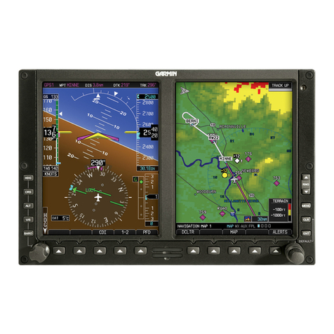
Garmin G500 User manual

Other manuals for G500

9

Other Garmin Avionic Display manuals

Garmin GTN 6 series User manual

Garmin

Garmin GTN 6 series User manual

Garmin Cessna Caravan G1000 User manual

Garmin

Garmin Cessna Caravan G1000 User manual

Garmin AOA System User manual

Garmin

Garmin AOA System User manual

Garmin G1000 NXi Owner's manual

Garmin

Garmin G1000 NXi Owner's manual

Garmin G500 User manual

Garmin

Garmin G500 User manual

Garmin Approach G5 - GPS-Enabled Golf Handheld Manual

Garmin

Garmin Approach G5 - GPS-Enabled Golf Handheld Manual

Garmin G3X Touch Manual

Garmin

Garmin G3X Touch Manual

Garmin GPSMAP 500 Series User manual

Garmin

Garmin GPSMAP 500 Series User manual

Garmin GTN 625 User manual

Garmin

Garmin GTN 625 User manual

Garmin Cessna Caravan G1000 User manual

Garmin

Garmin Cessna Caravan G1000 User manual

Garmin Approach G5 - GPS-Enabled Golf Handheld User manual

Garmin

Garmin Approach G5 - GPS-Enabled Golf Handheld User manual

Garmin G500 Manual

Garmin

Garmin G500 Manual

Garmin GTN 625 User manual

Garmin

Garmin GTN 625 User manual

Garmin G900X Manual

Garmin

Garmin G900X Manual

Garmin GFC 600H Manual

Garmin

Garmin GFC 600H Manual

Garmin Cessna Caravan G1000 Manual

Garmin

Garmin Cessna Caravan G1000 Manual

Garmin G600 Manual

Garmin

Garmin G600 Manual

Garmin GI 275 Reference guide

Garmin

Garmin GI 275 Reference guide

Garmin G500 User manual

Garmin

Garmin G500 User manual

Garmin Cirrus Perspective SR20 User manual

Garmin

Garmin Cirrus Perspective SR20 User manual

Garmin Cessna Caravan G1000 User manual

Garmin

Garmin Cessna Caravan G1000 User manual

Garmin GTN 6XX User manual

Garmin

Garmin GTN 6XX User manual

Garmin GPSMAP 400 series Installation and operating instructions

Garmin

Garmin GPSMAP 400 series Installation and operating instructions

Garmin GTN 635 User manual

Garmin

Garmin GTN 635 User manual

Popular Avionic Display manuals by other brands

Smart Avionics PB-4 Hardware manual

Smart Avionics

Smart Avionics PB-4 Hardware manual

Midcontinent SAM MD302 pilot's guide

Midcontinent

Midcontinent SAM MD302 pilot's guide

SDI C4 COMPETITION Handbook

SDI

SDI C4 COMPETITION Handbook

DYNANAV DynaFlight3 manual

DYNANAV

DYNANAV DynaFlight3 manual

DDC BU-67121W Hardware manual

DDC

DDC BU-67121W Hardware manual

Dynon SkyView HDX System Configuration manual

Dynon

Dynon SkyView HDX System Configuration manual

Genesys IDU-450 8.0H pilot's guide

Genesys

Genesys IDU-450 8.0H pilot's guide

EPIC OPTIX Eagle-2 user guide

EPIC OPTIX

EPIC OPTIX Eagle-2 user guide

Barco MDP 471/CH brochure

Barco

Barco MDP 471/CH brochure

Kanardia Digi manual

Kanardia

Kanardia Digi manual

Dynon SkyView HDX System System installation manual

Dynon

Dynon SkyView HDX System System installation manual

Barco CHDD-2000 Series Brochure & specs

Barco

Barco CHDD-2000 Series Brochure & specs

Flybox Eclipse Installation and operating manual

Flybox

Flybox Eclipse Installation and operating manual

Precision Flight Controls USB Throttle Quadrant Console user guide

Precision Flight Controls

Precision Flight Controls USB Throttle Quadrant Console user guide

Lynx Micro System instructions

Lynx

Lynx Micro System instructions

SAC SA100 manual

SAC

SAC SA100 manual

Spidertracks S5 quick start guide

Spidertracks

Spidertracks S5 quick start guide

PS Engineering PAR200A Installation and operation manual

PS Engineering

PS Engineering PAR200A Installation and operation manual

manuals.online logo
manuals.online logoBrands
  • About & Mission
  • Contact us
  • Privacy Policy
  • Terms and Conditions

Copyright 2025 Manuals.Online. All Rights Reserved.

GARMIN G500 QUICK REFERENCE
G500 Equipped Seminole Dierences
• The G500 powers on and o with the battery master, not the avionics master.
• There are no vacuum driven instruments, vacuum pumps, or suction gauge. Instruments are electrically powered.
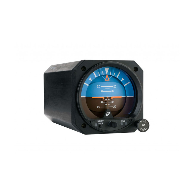
• The standby attitude indicator must be erected on power-up by pulling the cage knob.
• Test the standby attitude battery as directed by the After Start Checklist by pressing and holding the “STBY PWR”
button until amber LED begins ashing. A continuous green light beneath “TEST” during the full sequence indicates
that the battery is good. A red light illuminated anytime during the test indicates that the battery is not charged and
may require replacement.
• The standby attitude indicator warning light will blink for approximately 1 minute when the battery master switch is
turned o. DO NOT press the SBY PWR button as it causes continuous operation of the gyro on its emergency battery.
Exit the airplane with either a blinking LED or red ag.
• G500 equipped Seminoles do not have a conventional turn coordinator. A slip-skid indicator is located at the top of the
attitude indicator. Step on the “brick” instead of the “ball”. Use the reference lines and the magenta line that appears
above the heading indicator to identify a standard rate or half-standard rate turn.
• Outside air temperature (OAT) displays on PFD under the airspeed tape. There is no OAT probe or analog gauge
between the windows.
• Ground track can be identied on the heading indicator by a small magenta diamond near the lubber line (only visible
when ground track is dierent than heading).
• The digital altitude and airspeed readouts are very sensitive and can cause some pilots to continuously make
corrections for insignicant deviations. Pilot action - Don’t overcorrect for deviations of a few feet. Crosscheck digital
and analog standby instruments to avoid the tendency to overcorrect.
NOTE:
CDI needle indicates NAV source: green for VLOC /
magenta for GPS.
Checklist Dierences
Use the 2000 and later Seminole GNS 430 checklist with the
following dierences:
After Start Checklist
add: “MFD...................................... ENT / TIS Page” after GPS line item.
add: “SBY ATTITUDE............ PULL / RELEASE “ after NAVS line item.
Run Up Checklist
“SUCTION GAUGE..............................................................................N/A”
Shutdown Terminate Checklist
add (nal) item:
“SBY ATTITUDE..............................................BLINKING or FLAGGED”
(the STBY PWR warning light will blink for 1 minute when the battery master is selected
o, then the unit automatically turns o and the red gyro warning ag appears. DO
NOT press the SBY PWR button as it causes continuous operation of the gyro on its
emergency battery. Exit the airplane with either a blinking LED or red ag.)
Revised 2015-06-02
CAUTION:
The GNS 430 and G500 units each have their
own databases. Navigation, terrain and map
information on the G500 Multi-Function
Display (MFD) may not be current and is
not to be used for navigation. Use the G500
MFD for trac information only.
G500 Setup for Trac on MFD
ATP recommends setting-up the MFD to display the
decluttered Trac Information Service (TIS) page. Congure
the G500 screens during the After Start Checklist.
• Press
• Small MFD knob - (displays TIS page)
• 6 NM
ENT
RNG
2 clicks
PRIMARY FLIGHT DISPLAY (PFD)
MULTI-FUNCTION DISPLAY (MFD)
PFD Functions
These buttons toggle the function of the PFD knob.
ALT
BARO
CRS
HDG
V/S
Altimeter setting -
Set altitude bug and alerter -
Set heading bug -
Set V/S Bug -
Set course -
(push PFD knob to set heading bug to current heading.)
(when in VLOC mode)
(do not use)
GARMIN G500 QUICK REFERENCE
AHRS Failure
Indications - Failure of the Attitude
and Heading Reference System (AHRS)
is indicated by a removal of the sky/
ground presentation, a red X across
the Attitude Indicator, and a yellow
“ATTITUDE FAIL” and “HDG” messages
on the PFD. Rate-of-turn information
will not be available.
Pilot Action - Use standby attitude
indicator for attitude info and a
combination of the magnetic compass
and Garmin GNS 430 for heading. The
CDI will function normally.
Heading Failure
Indications - A complete Heading
Failure (magnetometer and GPS
ground track failure) is indicated by
the digital heading presentation
being replaced with a red X and
the compass rose digits being
removed.
Pilot Action - Use the magnetic
compass and the GNS 430s for
heading information.
ADC Failure
Indications - Complete loss of the Air
Data Computer (ADC) is indicated
by a red X and yellow text over the
airspeed, altimeter, vertical speed,
TAS and OAT displays. True airspeed
and wind calculations are also lost.
Pilot Action - Use standby airspeed
indicator and altimeter for speed
and altitude data. There is no backup
for theVSI, but known pitch attitudes
using the attitude indicator, power
settings, and airspeeds produce
consistent descent rates.
Electrical Failure
Indication - In the event of a total loss of electrical
power, the G500 system will be inoperative / dark.
The STBY PWR button on the standby attitude
indicator will begin blinking indicating it will turn o
in one minute.
Pilot Action - For attitude reference, press the “STBY
PWR” button on the standby attitude indicator
while blinking to operate using its integral
emergency battery. If the red warning ag appears
on the standby attitude instrument face, the unit is
powered o or inoperative and must not be used.
Use the standby airspeed, altimeter, compass, and
GNS430 for remaining ight data.
continued...