Bravo EV EVT- 4000e User manual

SERVICE MANUAL
SERVICE MANUAL
EVT- 4000e
EVT- 4000e

Table of Contents
1. Headlight Assembly
2. Headlight Bulb
3. Signal Light Bulb
4. Instrument Panel
5. Speedometer Cable
6. Speedometer Gear
7. Key Switch
8. Horn
9. Main Control Cord
10. Flasher Relay
11. DC to DC Converter
12. Left Handle Switch
13. Right Handle Switch
14. Brake Master Cylinder
15. Front Fork
16. Rear Shock Absorber
17. Front Brake Hose
18. Rear Brake Hose
19. Front Caliper
20. Rear Caliper
21. Controller
22. Motor
23. Rear Brake Disk
24. Front Brake Disk
25. Rear Light Assembly
26. Rear Lamp Bulb
27. Troubleshooting
28. Part Summary
1
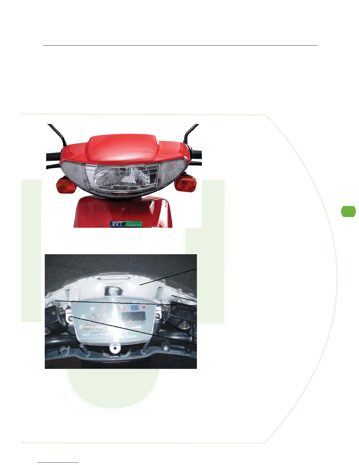
Headlight Assembly
1. Release three screws on the handle cover.
2. Release two mounting screws on the instrument panel, and then release three screws on
the head light assembly.
3. Follow with the reversed steps to restore.
Tools Required: Phillips screwdriver
Time: Allow 10 minutes for procedure
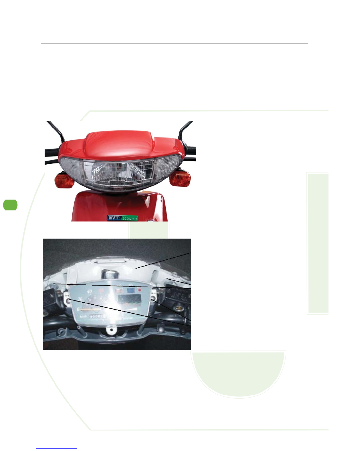
2
Headlight Bulb
1. Release three screws on the handle cover.
2. Release two mounting screws on the instrument panel.
3. Follow with the reversed steps to restore.
Tools Required: Phillips Screwdriver
Time: Allow 10 minutes for procedure
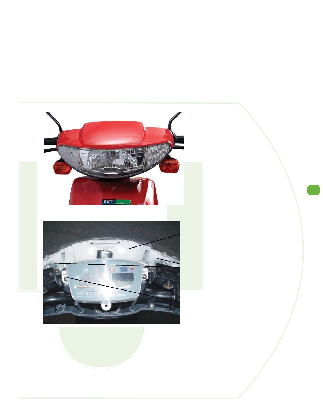
3
Signal Light Bulb
1. Release three screws on the handle cover.
2. Release signal light bulb set for replacement.
3. Follow with the reversed steps to restore.
Tools Required: Phillips screwdriver; T-bend socket wrench, 8mm
Time: Allow 10 minutes for procedure
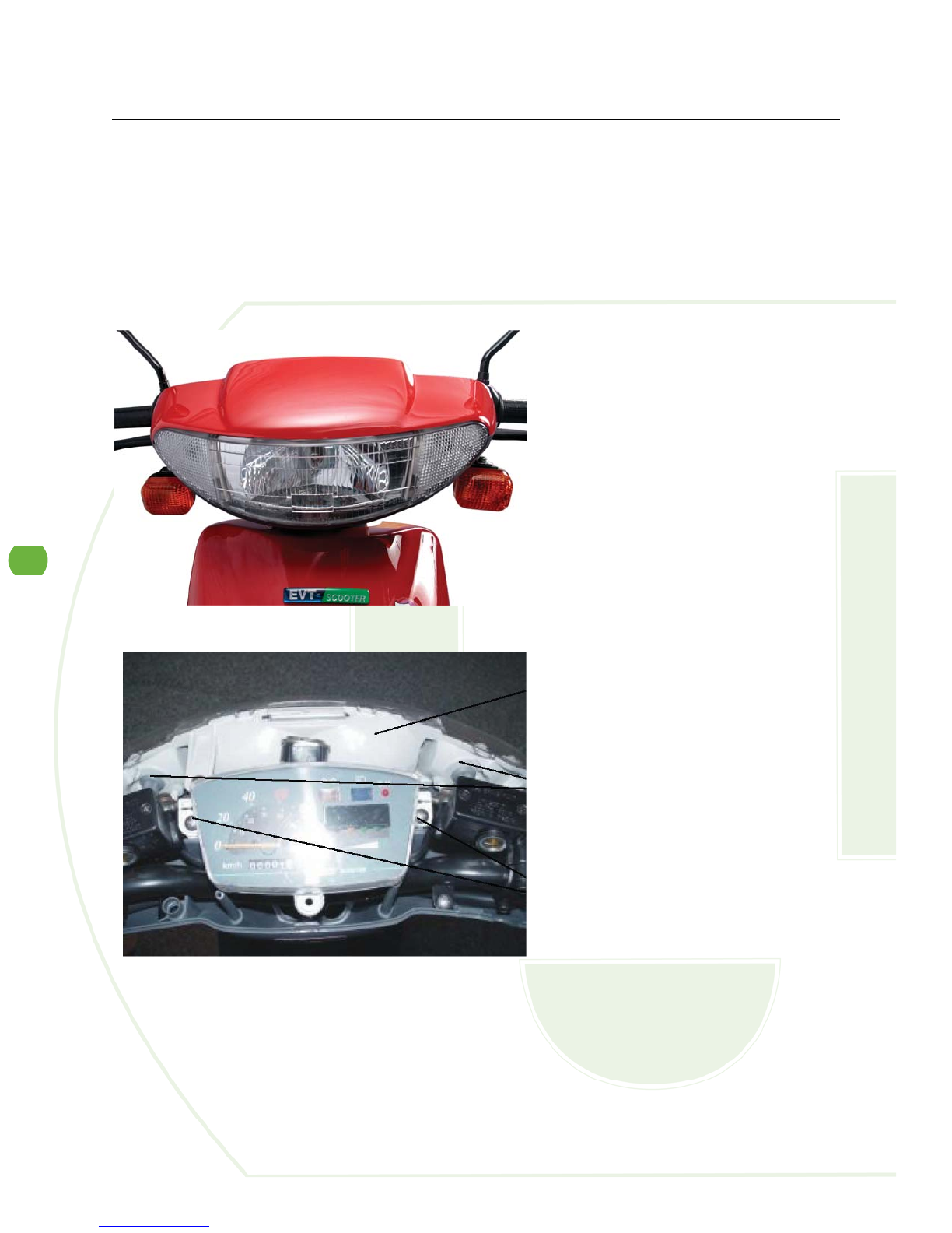
4
Instrument Panel
1. Release three screws on the handle cover.
2. Release two mounting screws on the instrument panel.
3. Release the nut for the speedometer.
4. Follow with the reversed steps to restore.
Tools Required: Phillips screwdriver
Time: Allow 10 minutes for procedure
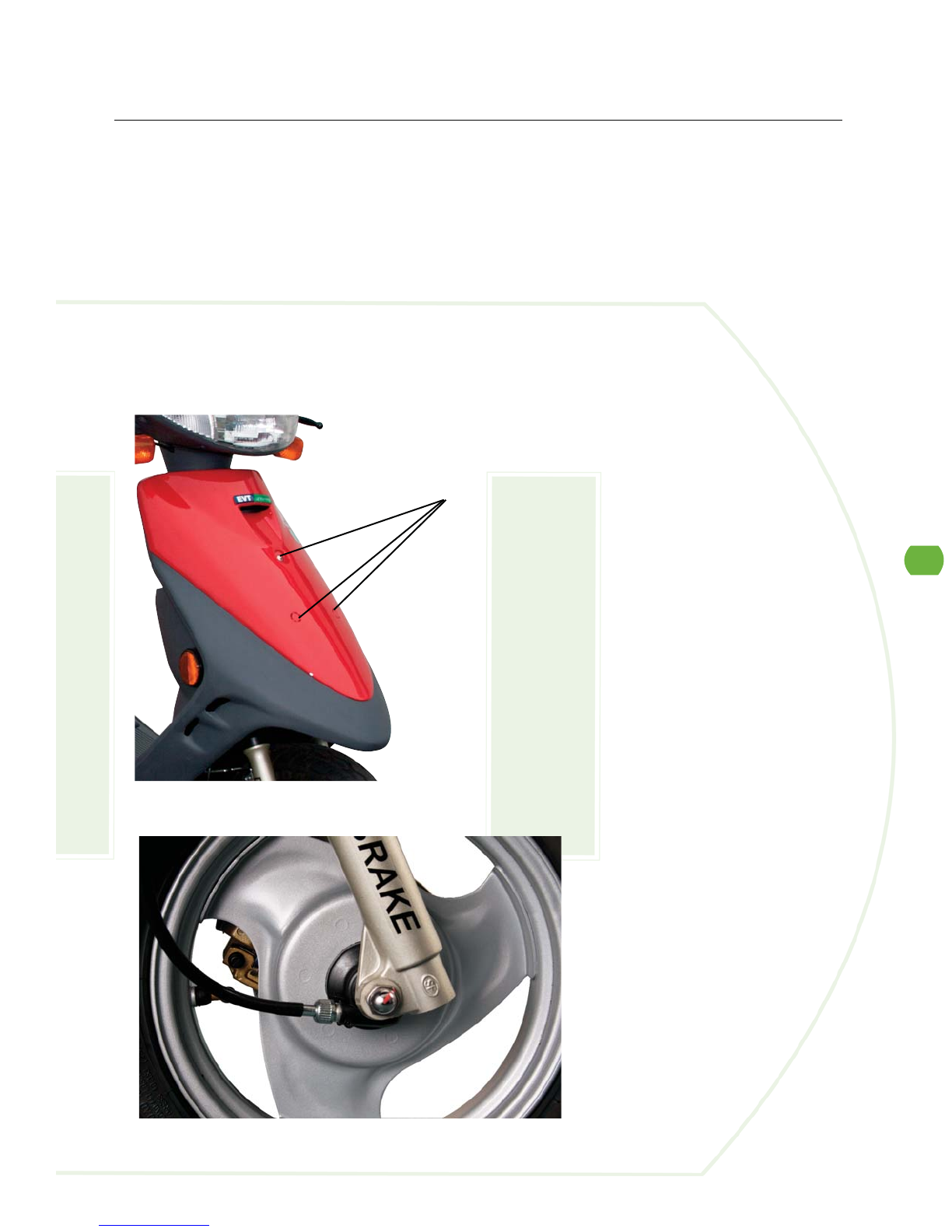
5
Speedometer Cable
1. Release three screws on the handle cover.
2. Release two mounting screws on the instrument panel.
3. Release the nut for the speedometer.
4. Release three screws on the front cover.
5. Release speedometer nut on the front wheel.
6. Follow with the reversed steps to restore.
Tools Required: Phillips screwdriver
Time: Allow 10 minutes for procedure

6
Speedometer Gear
1. Release front axle nut.
2. Remove the front wheel.
3. Follow with the reversed steps to restore.
Tools Required: Box wrench, 17mm
Time: Allow 10 minutes for procedure

7
Key Switch
1. Release three screws on the front cover.
2. Release six screws on the front fender.
3. Release three screws on the glove box.
4. Release 4-pin connector and two screws on the key switch.
5. Follow with the reversed steps to restore.
Tools Required: Phillips screwdriver; T-bend socket wrenches, 8mm and 10mm
Time: Allow 10 minutes for procedure
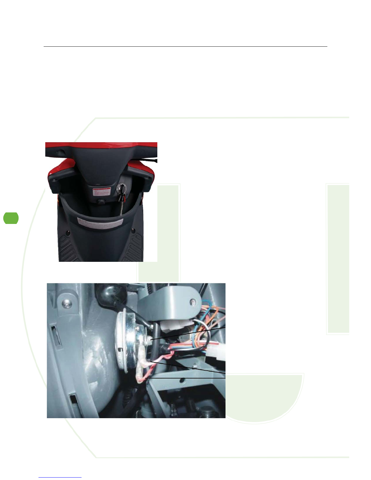
8
Horn
1. Release three screws on the front cover.
2. Release two connectors on the horn.
3. Release the mounting screws on the horn.
4. Follow with the reversed steps to restore.
Tools Required: Phillips screwdriver
Time: Allow 10 minutes for procedure

9
Main Control Cord
1. Release three screws on the handle cover, two mounting screws on the instrument panel,
three screws on the headlight, three screws on the front cover and two screws on the right
trim.
2. Release all of the connectors stores inside the handle cover.
3. Release all of the connectors stored inside the front cover.
4. Release all of the connectors stored inside the right cover.
5. Follow with the reversed steps to restore.
Tools Required: Phillips screwdriver
Time: Allow 10 minutes for procedure
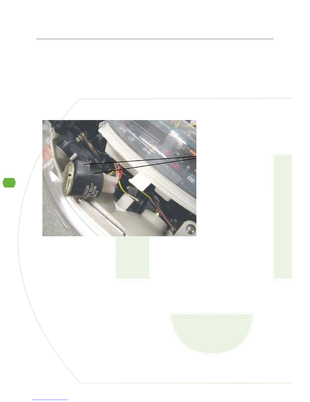
10
Flasher Relay
1. Release three screws on the handle cover, and remove the rubber sleeve so can see the 2
pin connector for the flasher relay.
2. Follow with the reversed steps to restore.
Tools Required: Phillips screwdriver
Time: Allow 10 minutes for procedure
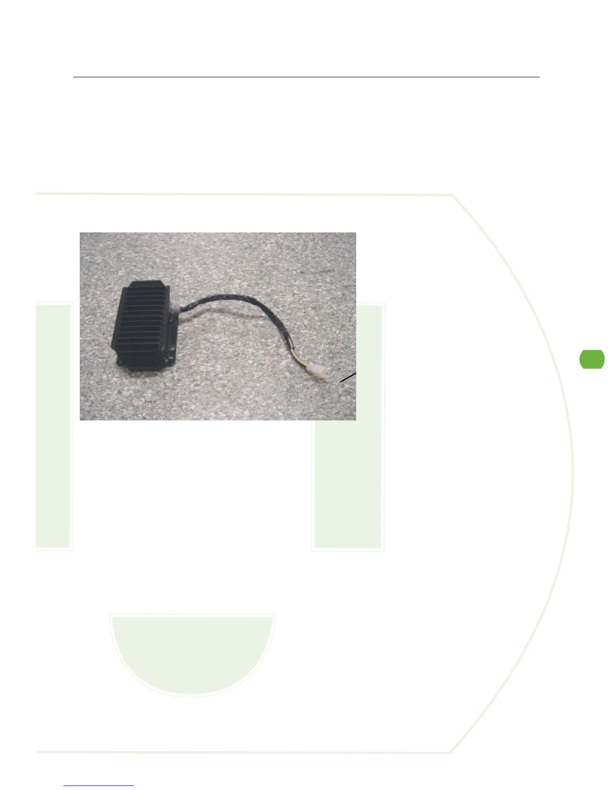
11
DC to DC Converter
1. Release three screws on the front panel.
2. Release two screws and 4-pin connector for the DC to DC converter.
3. Follow with the reversed steps to restore.
Tools Required: Phillips screwdriver
Time: Allow 10 minutes for procedure

12
Left Handle Switch
1. Remove left rear view mirror and release three screws on the handle cover.
2. Release two mounting screws on the instrument panel.
3. Release two screws on the left handle switch.
4. Follow with the reversed steps to restore.
Tools Required: Phillips screwdriver; open-end wrench, 14mm
Time: Allow 10 minutes for procedure
13
Right Handle Switch
1. Remove the right rear mirror and three screws on the handle cover.
2. Release two mounting screws on the instrument panel.
3. Release two screws on the right handle switch and one screw for the throttle cable.
4. Follow with the reversed steps to restore.
Tools Required: Phillips screwdriver; Open-end wrench, 14mm
Time: Allow 10 minutes for procedure

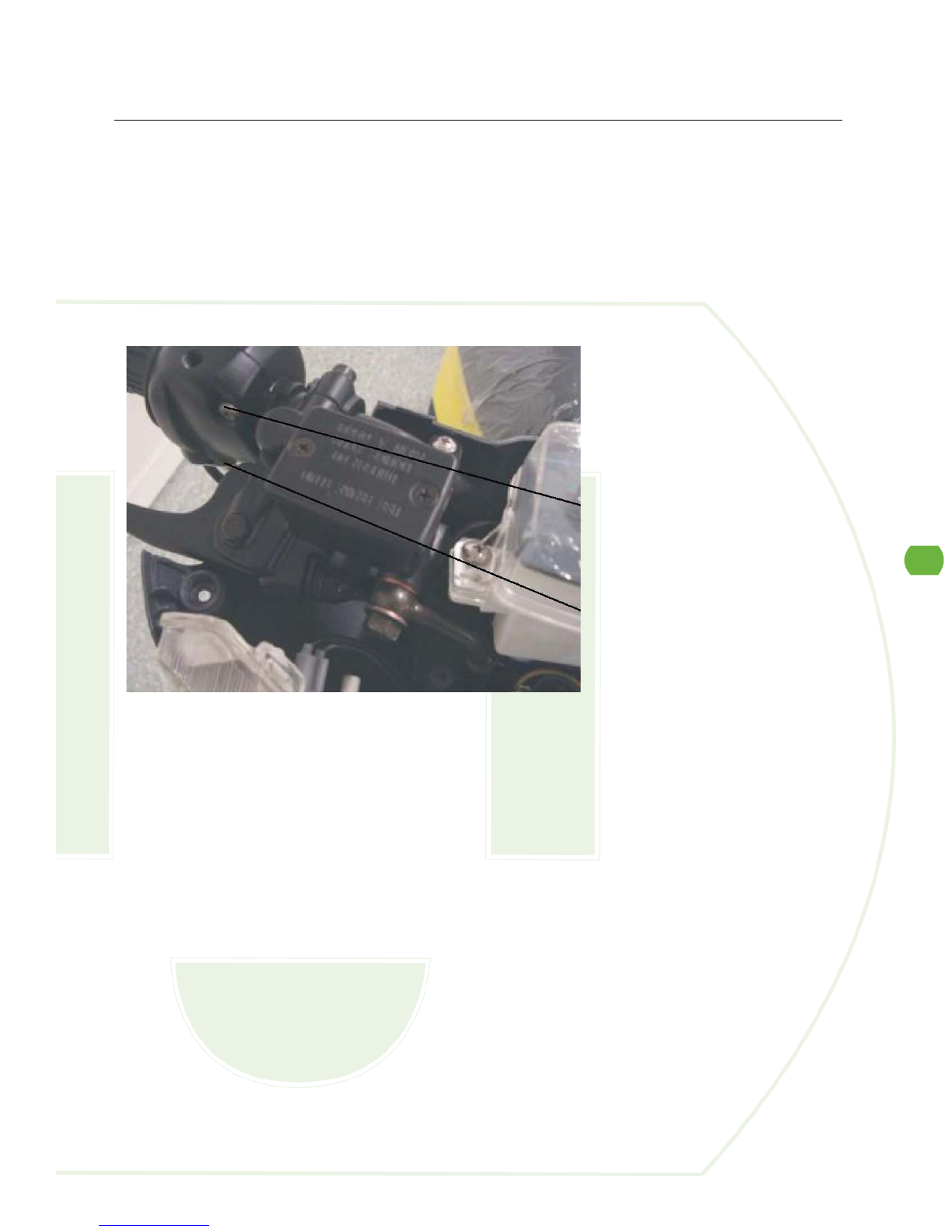
14
Brake Master Cylinder
1. Release three screws on the handle cover, two mounting screws on the instrument panel
and three screws on the headlight assembly.
2. Check the fluid in reservoir for refuel or replace the blake fluid.
3. Replace reservior for a.) gasket fail or wear out, or b.) leaking.
4. Release the screw on the brake hose.
5. Release two screws on the reservoir.
Tools Required: Phillips screwdriver; Box wrench, 12mm; Hex key wrench, 5mm
Time: Allow 10 minutes for procedure

15
Front Fork
1. Release three screws on the front cover.
2. Release six screws on the front fender.
3. Release three screws on the glove box.
4. Release clamping screw for the handle.
5. Release front axle nut to remove the wheel.
6. Release two screws on the caliper.
7. Release two screws on the front fork and check the steel balls to see if they are missing.
8. Properly adjust the front fork clearance and follow the reversed steps to restore.
Tools Required: Phillips screwdriver; T-bend socket wrench, 8mm; Box wrenches, 14mm and
17mm; Y-bend socket wrench, 12mm
Time: Allow 10 minutes for procedure
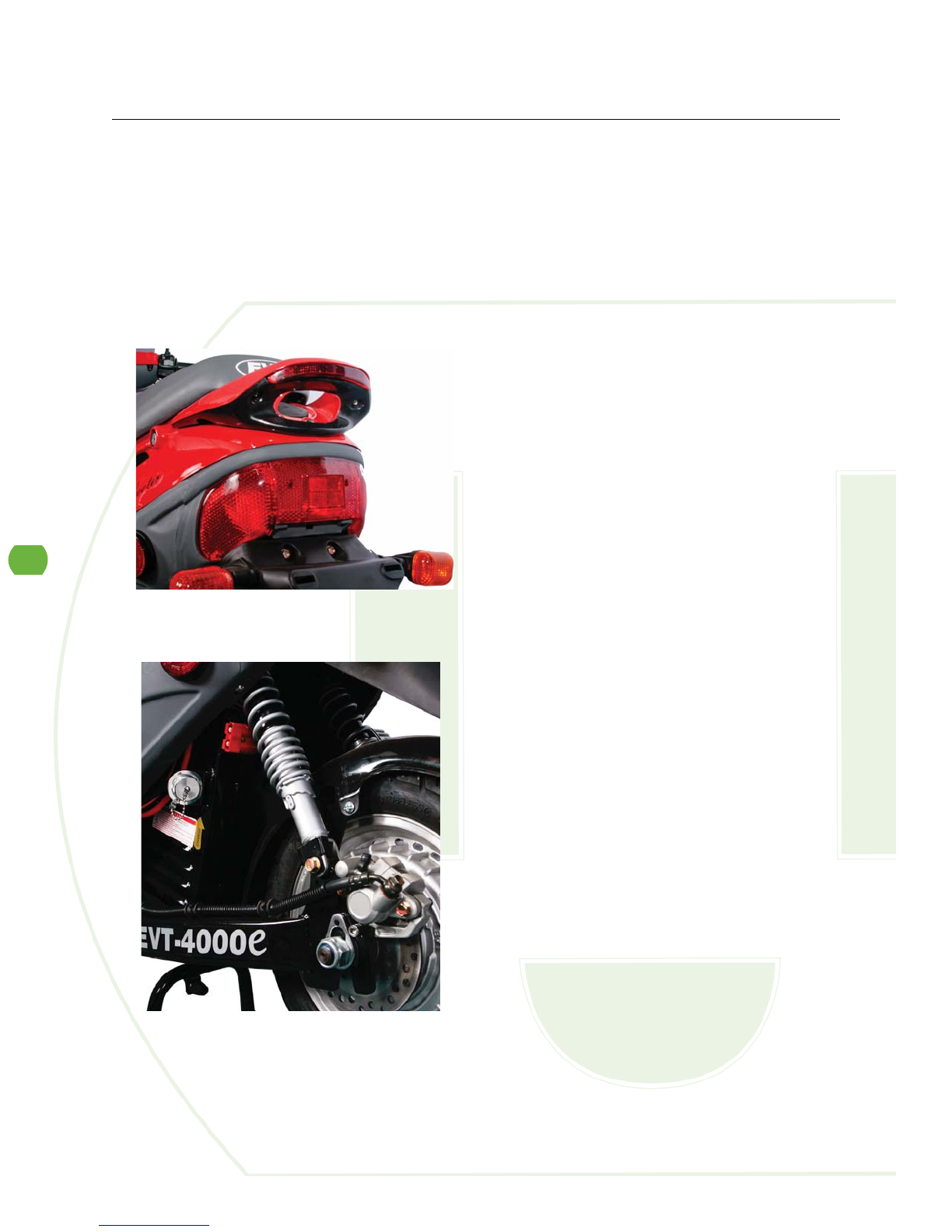
16
Rear Shock Absorber
1. Release two screws on the trim on each left and right side.
2. Release two screws on the left shock absorber.
3. Repeat to replace right shock absorder.
4. Follow with the reversed steps to restore.
Tools Required: Phillips screwdriver; T-bend socket wrenches, 12mm and 14mm
Time: Allow 10 minutes for procedure

17
Front Brake Hose
1. Release three screws on the handle cover.
2. Release two screws on the right reservoir.
3. Release the screw on the brake hose of the front wheel Avoid fuel leaking to the pad.
4. Release the screw on the right side brake hose.
5. Release three screws on the front cover.
6. Cut off the band, then carefully pull out the hose.
7. Follow with the reverse steps to restore.
Tools Required: Phillips screwdriver; Box wrench, 12mm; diagonal cutting pliers
Time: Allow 10 minutes for procedure

18
Rear Brake Hose
1. Release three screws on the handle cover.
2. Release two screws on the left reservoir.
3. Release the screw on the brake hose of the rear wheel Avoid fuel leaking to the pad.
4. Release the screw on the left side brake hose.
5. Release three screws on the front cover.
6. Release six screws on the front fender.
7. Release two screws on the left trim.
8. Cut off the band, and carefully pull out the hose.
9. Follow with the reversed steps to restore.
Tools Required: Phillips screwdriver; Box wrench, 12mm; Diagonal cutting pliers
Time: Allow 10 minutes for procedure
Table of contents


