Alta Motors Redshift MX 2017 Application guide

2
Congratulations on your purchase of an Alta Motors Redshift!
The Redshift is engineered to compete, and performs like a 250cc bike.
While you’re getting used to it, be cautious and pay attention to available
traction in both acceleration and braking.The smooth throttle delivery and
lack of combustion-derived noise means the Redshift can be deceptively
fast: you don’t want any unpleasant surprises.
PLEASE READ THIS MANUAL CAREFULLY AND COMPLETELY BEFORE OPERATING THIS MACHINE.
DO NOT ATTEMPT TO OPERATE THIS MACHINE UNTILYOU HAVE ATTAINED A SATISFACTORY
KNOWLEDGE OF ITS CONTROLS AND OPERATING FEATURES AND UNTIL YOU HAVE BEEN
TRAINED IN SAFE AND PROPER RIDING TECHNIQUES. REGULAR INSPECTIONS AND CAREFUL
MAINTENANCE, ALONG WITH GOOD RIDING SKILLS, WILL ENSURE THAT YOU SAFELY ENJOYTHE
CAPABILITIES AND THE RELIABILITY OF THIS MACHINE.
Always wear a helmet. Before you go “Throttle Live,” make sure your helmet is on.
The Redshift is designed for one person only.
Unlike a traditional gas-powered motorcycle, the Redshift doesn’t require much maintenance.
However, the source of its power produces extremely high voltage and amperage. DO NOT tamper
with the electrical system! There are no user-serviceable electrical powertrain components housed
in the bike. See your authorized Alta Motors dealer when the need for diagnosis or repairs arise.
If the battery pack in particular gets dented, cracked, punctured, or yielded in any way, take your
Redshift to your local dealer to have a complete inspection done.
Please do not attempt to operate your Redshift under the influence of any drugs, prescription or
recreational, including Alcohol.
Failure to follow WARNING instructions could result in severe injury or death to the machine
operator, a bystander, or a person inspecting or repairing the machine.
This manual will provide you with a good basic understanding of features, operation, and basic
maintenance and inspection items of this machine. Please read this manual carefully and
completely before operating your new machine.

3
CHAPTER 1 – GENERAL INFORMATION
Getting Started
Regular Inspection and Adjustments
CHAPTER 2 – BODYWORK
Fender (front) – Removal & Installation
Fender (rear) – Removal & Installation
Mud Flap – Removal & Installation
Number Plate (front) – Removal & Installation
Number Plate (rear) – Removal & Installation
Rock Guard – Removal & Installation
Seat – Removal & Installation
Shrouds – Removal & Installation
Subframe – Removal & Installation
CHAPTER 2 – BRAKES
Brake Caliper (Front, MX), Removal & Installation
Brake Caliper (Front, SM), Removal & Installation
Brake Caliper (Rear, MX & SM), Removal & Installation
Brake Caliper, Overhaul
Brake Disc, Removal & Installation
Brake Hydraulic System, Bleeding
Brake Lever, Removal & Installation
Brake Master Cylinder (Front), Removal & Installation
Brake Master Cylinder (Rear), Removal & Installation
Brake Master Cylinder, Overhaul
Brake Pad Replacement (Front, MX)
Brake Pad Replacement (Front, SM)
Brake Pad Replacement (Rear, MX and SM)
Brake Pedal, Removal & Installation
TABLE OF CONTENTS

4
CHAPTER 4 – SUSPENSION / STEERING / WHEELS / FINAL DRIVE
Drive Chain – Maintenance
Drive Chain – Removal & Installation
Forks – Removal & Installation
Front wheel – Removal & Installation
Grips – Replace
Handlebar and Mounts – Removal & Installation
Rear Wheel – Removal & Installation
Shock Absorber – Removal & Installation
Shock Linkage – Remove/bearing Service/install
Primary Drive Sprocket – Removal & Installation
Steering Head Bearings – Service/Replace
Suspension – Adjustments
Swingarm – Remove/ Bearing Service/Install
Triple Clamps/Steering Stem – Removal & Installation
Wheel seals and bearings – Replace
CHAPTER 5 – COOLING SYSTEM
Coolant – Drain/Refill
Coolant Pump – Removal & Installation
Coolant Hose(s) – Replace
CHAPTER 6 – POWERTRAIN / BATTERY / CONTROL SYSTEM /
MOTOR / PRIMARY DRIVE
Accessory Control Module (ACM) – Removal & Installation
Battery – Disconnection/Reconnection
Battery – Removal & Installation
Charge Inlet (Delta Wing) – Removal & Installation
DC Charge Port (DCCP) – Removal & Installation
Drive and Driven Gears – Removal & Installation
Gearbox Cover – Removal & Installation
HV Connector – Removal & Installation
Motor Controller - Removal & Installation
Motor and Output Shaft – Removal & Installation
Output Shaft Bearings - Replace

5
Output Shaft Seal – Replace
Position Sensor – Removal & Installation
Primary Drive Sprocket – Removal & Installation
Timing Cover – Removal & Installation
CHAPTER 7 – FRAME
Boot Guards – Removal & Installation
Bulkhead – General Information/Servicing
Footpegs – Removal & Installation
Sidestand – Removal & Installation
Skidframe – Removal & Installation
CHAPTER 8 – LOW VOLTAGE ELECTRICAL
Brake Light Switches – Removal & Installation
Display – Removal & Installation
Headlight Adjustment
Headlight Housing - Removal & Bulb Replacement
Horn – Removal & Installation
Ignition Switch – Removal & Installation
License Plate Light
Map Switch – Removal & Installation
Marker Light
Sidestand Switch – Removal & Installation
Start/Stop/Run Switch – Removal & Installation
Taillight
Throttle Switch/Tube – Removal & Installation
Turn Signal/Horn/HI-LO Beam Switch – Removal & Installation
Turn Signals/Running Lights

6RETURN TO TABLE OF CONTENTSRETURN TO TABLE OF CONTENTSRETURN TO TABLE OF CONTENTSRETURN TO TABLE OF CONTENTSRETURN TO TABLE OF CONTENTS
RETURN TO TABLE OF CONTENTS
GETTING STARTED
STOP BUTTON
FRONT BRAKE
THROTTLE
RUN BUTTON
START BUT TON
DI SPL AY PAN EL
CHARGE PORT
PERFORMANCE
MAP SELECTOR
ON / OFF KEY
CHAPTER 1

7
RETURN TO TABLE OF CONTENTSRETURN TO TABLE OF CONTENTSRETURN TO TABLE OF CONTENTSRETURN TO TABLE OF CONTENTSRETURN TO TABLE OF CONTENTS
RETURN TO TABLE OF CONTENTS
OPERATING CONTROLS
The Redshift is a very intuitive bike to ride, but before you twist the throttle, take some time
to become familiar with the controls. The first thing you’ll notice is the lack of a clutch lever
on the left side of the handlebar, and the missing shift lever below the left footpeg. This is
one of the main features that sets this bike apart from its gasoline-powered counterparts.
The single-speed clutchless drive of the 14,000 rpm AC Motor allows you to concentrate
on riding technique.
1. Key Switch – located on the left shroud is a standard
Off/On switch. Rotate the key clockwise to activate the
RUN circuit. note that with the key in the on position,
it is flush with the bodywork. (. )
2. RUN-STOP switch – located on the right side of the
handlebar, this is what feeds or cuts power to the
motor and charger. (. )
3. START button – located just below the RUN-STOP
switch, this is what brings the bike to life after the key
switch is turned On and the RUN-STOP switch has
been set to RUN. You can disable the motor/throttle
again by cycling the RUN-STOP switch– this will bring
the bike back to an idle state. Once stopped please
get into the habit of switching the run-stop switch off
so that you don’t accidentally actuate the throttle
while the motor is energized.
. .
GETTING STARTED

8RETURN TO TABLE OF CONTENTSRETURN TO TABLE OF CONTENTSRETURN TO TABLE OF CONTENTSRETURN TO TABLE OF CONTENTSRETURN TO TABLE OF CONTENTS
RETURN TO TABLE OF CONTENTS
4. Throttle – same place as on any bike, but to say it
works in the same manner would be misleading.
Yes, you twist it to go, but you’ll have 100% of the
bike’s torque available in your right hand, from the
start. Be careful!
5. Performance Map switch – located on the left side
of the handlebar, this switch changes the bike’s
“personality” to fit your current riding conditions.
Depressing the Up button changes the map number to
the next numerically higher map. Depressing the
Down button does just the opposite. (. )
6. Front brake lever – located on the right end of the
handlebar. Adjust the length of pull by turning the
knob just to the inside of the lever pivot. (. )
7. Rear brake pedal – located down at the right
footpeg. Lever position can be adjusted by loosening
the bolt and turning the adjustment cam (A). If this is
done, though, pedal freeplay will have to be adjusted
by altering the length of the rear brake master
cylinder pushrod (B). There should be 3-5mm of
freeplay at the tip of the lever before the lever
actuates the plunger. (. ).
.
.
CHAPTER 1

9
RETURN TO TABLE OF CONTENTSRETURN TO TABLE OF CONTENTSRETURN TO TABLE OF CONTENTSRETURN TO TABLE OF CONTENTSRETURN TO TABLE OF CONTENTS
RETURN TO TABLE OF CONTENTS
UNDERSTANDING THE PERFORMANCE MAPS
The Redshift is equipped from the factory with 4 performance maps. These performance
maps are not “gears,” but rather tools to adapt the characteristics of the Redshift
to different riding styles and terrain conditions. The maps work by changing the
parameters of power delivery relative to the throttle position and regenerative braking
on deceleration. You may find that you are faster in slippery conditions when using Map
1. When traction is good, Map 4 may be your fastest option. Try them all out in different
conditions to see what suits you and your riding environment.
The regenerative braking (regen) acts as resistance when the throttle is off. The more
regen, the more power is being produced, the more it will slow you down without the
use of the conventional disc brakes.
MAP 4
OVERCLOCKED
MILD
MILD
HIGH
HIGH
HIGH
MAP 3
PERFORMANCE
MILD
MILD
MEDIUM
MEDIUM
MED-HIGH
MAP 2
MX RACE
MEDIUM
MILD
HIGH
MEDIUM
MEDIUM
MAP 1
TRAIL
HIGH
MEDIUM
MILD
MILD
MILD
TRACTION
REGEN
RESPONSE
TOP
BOTTOM
GETTING STARTED
MAP 4
OVERCLOCKED
MILD
HIGH
HIGH
HIGH
HIGH
MAP 3
COMMUTE-2
MEDIUM
MEDIUM
MEDIUM
MEDIUM
MEDIUM
MAP 2
COMMUTE-1
MEDIUM
MILD
MEDIUM
MEDIUM
MEDIUM
MAP 1
RAIN
HIGH
MILD
MILD
MILD
MILD
TRACTION
REGEN
RESPONSE
TOP
BOTTOM

10 RETURN TO TABLE OF CONTENTSRETURN TO TABLE OF CONTENTSRETURN TO TABLE OF CONTENTSRETURN TO TABLE OF CONTENTSRETURN TO TABLE OF CONTENTS
RETURN TO TABLE OF CONTENTS
STARTING UP
THROTTLE LIVE
OPERATING YOUR REDSHIFT
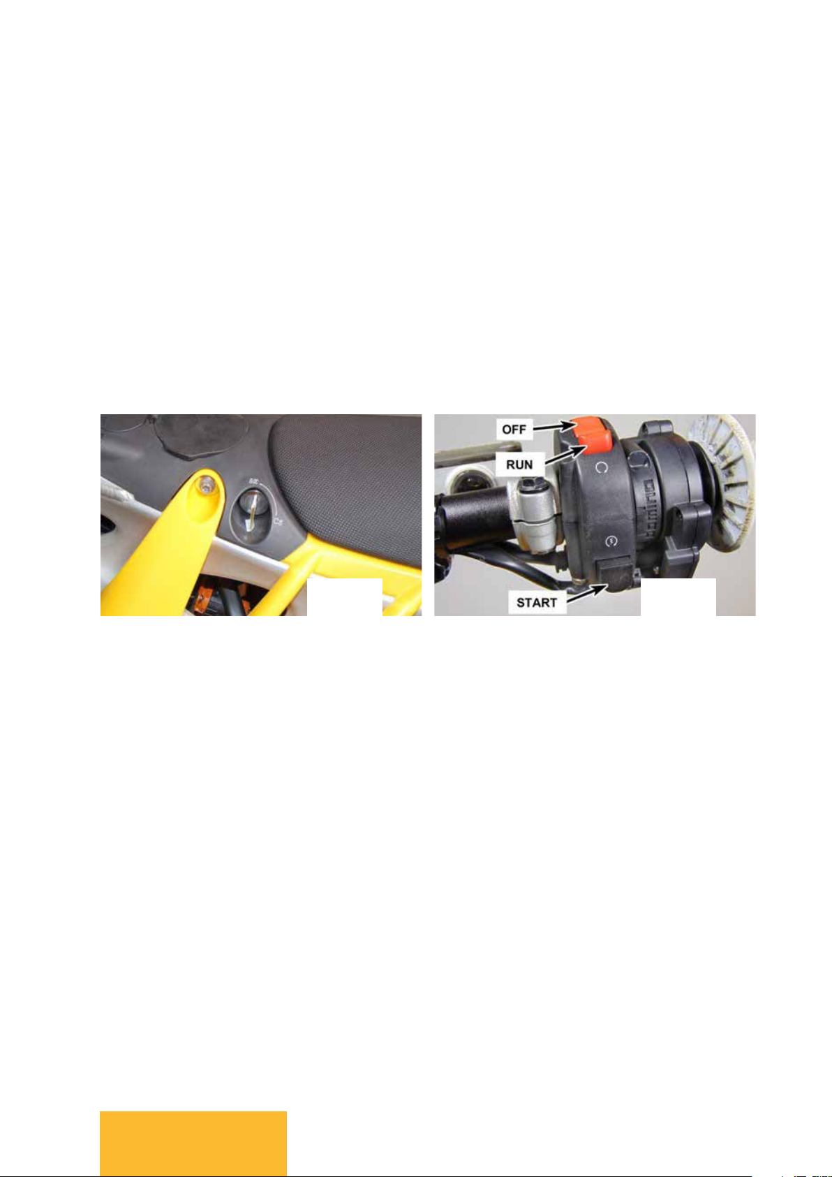
1. Turn the key clockwise to the ON position. The
display will light up, giving you information about the
state of charge, map selection, and total mileage. You
may also hear the coolant pump power up and begin
to circulate coolant through the frame.
2. Set the red RUN-STOP switch to RUN.
3. With the throttle fully closed, press the START
button. The throttle is now live!
1. The Redshift is now LIVE, and the perimeter of the
display panel will pulse green to indicate live throttle.
This pulsing will stop once you are moving, and will
resume when you come to a stop.
2. The Redshift has no clutch and makes almost no
noise when stationary. Once you twist the throttle,
the bike will respond immediately. It’s a smart
practice to always cycle the RUN-STOP switch to
deactivate the throttle after a ride, for an emergency
stop, or any time when you’re stopping for more than
a traffic light.
If the HV battery is below freezing temperature, it
will refuse to charge, and drive power will be
reduced. Capacity (driving range) will also be
reduced at low temperature.
Over-discharge may result in permanent damage to the
HV battery, and replacement may be necessary. The HV
battery has a gradual self-discharge rate, and will lose
charge if left unused for long periods of time. Do not
leave the HV battery below 10% charge for more than
one week, or below 25% for more than one month.
When storing the HV battery, charge it to 40-60% (or
higher) and check it monthly, recharging if needed.
The HV battery will gradually lose capacity with time
and use, just like any rechargeable battery. The rate of
capacity loss depends on how the pack is used, but
lower sustained temperatures and lower power draw
(less aggressive riding, especially at highway speeds)
will prolong battery life.
There is no specific point at which the HV battery
needs to be replaced. The capacity (range) and
available power will simply continue to decrease.
Contact your Alta dealer for proper disposal and
replacement of your HV battery.
The regenerative braking system applies a braking
torque at the rear wheel to add charge back into the
HV battery; the amount of “regen” applied varies with
throttle position and throttle map. This system is not
connected to the vehicle’s hydraulic braking system or
brake levers in any way, and should not be depended
on to stop the vehicle in an emergency. When the HV
battery is full, regen will be automatically reduced to
prevent overcharge.
CHAPTER 1

11
RETURN TO TABLE OF CONTENTSRETURN TO TABLE OF CONTENTSRETURN TO TABLE OF CONTENTSRETURN TO TABLE OF CONTENTSRETURN TO TABLE OF CONTENTS
RETURN TO TABLE OF CONTENTS
HOW TO CHARGE YOUR REDSHIFT
1. Pull up the cover on the charge port located on
the motorcycle and plug in the charging connector.
2. Set the vehicle charger upright (on its rubber feet
with the fan perpendicular with the ground. ) and
plug the charger’s cord into an electrical outlet.
Keep the charger away from flammable materials,
and make sure it has adequate airflow for cooling.
3. Make sure the Ground Fault Circuit Interrupter
(GFCI) on the AC cord has been reset. If it has been
reset properly the green light on the GFCI will be lit.
4. Turn the key to the ON position, and set the red
RUN-STOP button to the RUN position. The LED on
the charger flashes green when it is on standby, and
will flash red when charging has begun.
5. Turn the key to OFF and let the bike’s battery
charge. Cause of the charger’s “smart”
capabilities there’s no need to worry about
overcharging the battery.
6. The display provides feedback about the state of
charge during the charging phase, and when the
LED turns green, the charging phase is complete.
7. Unplug the charger from the wall outlet; coil the
cords, and store the charger in a safe area.
A complete charge can take up to six hours at 110v. Ride times will vary depending
on terrain and how aggressively you use the throttle.
GETTING STARTED

12 RETURN TO TABLE OF CONTENTSRETURN TO TABLE OF CONTENTSRETURN TO TABLE OF CONTENTSRETURN TO TABLE OF CONTENTSRETURN TO TABLE OF CONTENTS
RETURN TO TABLE OF CONTENTS
HIGH VOLTAGE SAFETY
WARNING: Y L-I H V (HV)
. I HV ,
, , .
HIGH VOLTAGE (HV) BATTERY
AND DRIVE SYSTEM
IF THE HV SYSTEM IS DAMAGED
The HV battery and drive system operates up to 400V
DC. The system can be “live” during and after the
vehicle is powered up, and for up several minutes
after the vehicle is shut off.
Never disassemble, remove or replace high-voltage
components - all HV system components can only be
serviced by an Alta dealer. High-voltage cables are
colored orange, and all related components have
warning labels on them. Obey all warning labels on
the vehicle.
After an accident, inspect for exposed wiring,
damaged connectors or damaged housings of any
high-voltage components. Do not attempt to touch
wiring or exposed parts. If any part of the HV system is
damaged, bring the vehicle to your Alta dealer
immediately. If damaged wiring or electrical
components are in danger of touching the chassis or
the extent of damage is unclear, do not touch the
vehicle, and call an emergency service like 911 to
handle it.
I ,
H V
.
Damage to the HV battery system may result in an
electrolyte leak. Avoid contact with the electrolyte
and do not inhale the fumes; if contact occurs, flush
eyes or skin with water immediately. The electrolyte
is flammable: keep any flame or hot objects away
from a leak.
Extreme damage to the HV battery can cause a fire. If
a HV battery fire occurs, the most effective response is
to douse it heavily with fresh water or bury it in sand.
A fire extinguisher will only reduce the flame
temporarily; it will not remove the heat and therefore
will not stop the reaction taking place.
After a HV battery fire has subsided, it may still be
generating enough internal heat to re-ignite. Keep the
HV battery away from flammable materials and monitor
it for at least 2 hours after it has cooled completely.
CHAPTER 1

13
RETURN TO TABLE OF CONTENTSRETURN TO TABLE OF CONTENTSRETURN TO TABLE OF CONTENTSRETURN TO TABLE OF CONTENTSRETURN TO TABLE OF CONTENTS
RETURN TO TABLE OF CONTENTS
CHARGING SAFETY
To avoid risk of electrical shock, fire, and serious injury or death:
• Only use a charger
that is approved by
Alta Motors for use with
your vehicle model.
• Have any outlet used
for charging inspected
by a licensed
electrician. Inspection
should include
verifying proper
grounding, sufficient
current handling,
dedicated circuit, and
breaker function.
• If you use any life-
sustaining medical
electrical devices,
check with the
manufacturer about
the effects that
charging may have on
that device.
• Charge outdoors or in
large ventilated areas.
Do not use a vehicle
cover during charging.
• Do not charge with
building wiring more
than 40 years old.
• Do not charge if
outlet appears
damaged or will not
hold plug firmly.
• If your AC cord is
equipped with a
GFCI, test it monthly
(“TEST” button).
• Do not charge with
other devices plugged
into the same circuit.
• Do not use unapproved
extension cords or plug
adapters to charge.
• Do not touch exposed
connector terminals.
• Do not move the vehicle
while charging.
• Do not touch the
vehicle or charger
when there is lightning.
A lightning strike may
feed back into the
charging system.
• Do not disassemble or
modify the charger or
vehicle connector.
Plug should be
modified only by a
licensed electrician.
• Stop charging
immediately if charge
plug or outlet becomes
hot to the touch.
• Do not charge near fire,
heat, flammable
materials, or water.
• Make sure there is no
water or debris in the
charge port, connector
or electrical plug, and
that they are not
damaged, rusted or
corroded. Make sure
the charge port cap is
closed once charging is
finished to prevent
water and foreign
debris from entering.
• Do not unplug
anything until
charging has been
disabled by setting
the run/stop switch to
the “stop” position.
GETTING STARTED

14 RETURN TO TABLE OF CONTENTSRETURN TO TABLE OF CONTENTSRETURN TO TABLE OF CONTENTSRETURN TO TABLE OF CONTENTSRETURN TO TABLE OF CONTENTS
RETURN TO TABLE OF CONTENTS
To obtain the best performance from your Redshift, and for your own safety, it’s important
to take a few moments to make sure everything is in working order before you ride:
REGULAR INSPECTION
& ADJUSTMENTS
1. Your tires are the most important link in the chain
between you and the earth. Correct pressure will ensure
you get the best handling from your Redshift, and
checking the condition of the tires often will reduce the
chance of failure while out on the track or trail.
2. Use a pressure gauge to check the air pressure in the
tires. For motocross riding, 14 psi is a good starting
point. For soft conditions, you can get better traction
buy dropping the pressure as low as 12 psi. For off-road
riding, consider increasing the pressure to 18 or 20 psi;
the bike will be “looser,” but the risk of pinch flats will
be greatly reduced. For the Redshift SM, 24 psi is a
good starting point.
3. Check the tires carefully for cuts in the sidewalls
and in between the knobbies.
4. Make sure the valve stem has not shifted. This
failure mode is more common when running lower
pressures. If this happens, you will ll have to deflate
the tire, loosen the rim lock, unseat the tire’s bead
from the rim and shift the tire/tube until the valve
stem is straight. Then re-inflate the tire to the proper
pressure, and tighten the rim lock nut securely.
5. Always verify that there is plenty of tread left on
your tires before heading out for a ride.
TIRES
Visually inspect the HV battery, motor controller and
motor monthly for signs of damaged wiring, cracked/
broken housings or broken seals. Any damage should
be reported to your Alta dealer immediately.
HV DRIVE SYSTEM
CHAPTER 1

15
RETURN TO TABLE OF CONTENTSRETURN TO TABLE OF CONTENTSRETURN TO TABLE OF CONTENTSRETURN TO TABLE OF CONTENTSRETURN TO TABLE OF CONTENTS
RETURN TO TABLE OF CONTENTS
BRAKES
1. Make sure the braking system is in perfect working
order to stay ahead of the pack, protect your
investment, and avoid injury.
2. Check the brake fluid level in the front and rear
master cylinder reservoirs. Each reservoir has a sight
glass that enables you to check the fluid level. An
overfilled or underfilled brake reservoir is dangerous.
(. )
3. If fluid is required, first check the master cylinder,
fluid hose and caliper for leakage. If any leaks are found,
fix them immediately. The fluid level will drop as the
brake pads wear.This is normal; just don’t let the fluid
level in the reservoir drop below the MIN mark.
4. If it is necessary to add fluid, remove the reservoir
cap and add DOT 4 brake fluid until it is at the MAX
mark or top of the sight glass. Before reinstalling the
cap and diaphragm, check the condition of the
diaphragm. It is normal for the diaphragm in the front
master cylinder reservoir to expand as the pads wear
and the fluid level drops. Push the center of the
diaphragm back into place to retract it before
installing it and the cap.
5. Check the brake pads for wear. It’s critical that the
pads be replaced before the pad friction material
wears down below the minimum allowable thickness
of 1.5 mm. As the pads thickness decreases the wear
rate increases, that last couple of mm of pad material
will disappear much quicker than the first few mm.
(. )
6. Operate the front brake lever and rear brake pedal
– they should both feel firm, not spongy. If not, there
is either air in the hydraulic system (which means the
affected system must be bled) or the master cylinder
seal for that system has failed (or is about to fail).
. .
. .
REGULAR INSPECTION & ADJUSTMENTS

16 RETURN TO TABLE OF CONTENTSRETURN TO TABLE OF CONTENTSRETURN TO TABLE OF CONTENTSRETURN TO TABLE OF CONTENTSRETURN TO TABLE OF CONTENTS
RETURN TO TABLE OF CONTENTS
1. The Redshift relies on coolant to keep motor and
controller temperatures in check and gear oil to
lubricate the primary drive gears.
2. It isn’t necessary to check these levels daily, but if a
leak IS discovered or the level is low chronically, the
problem must be diagnosed. It is normal for a small
amount of coolant to overflow from the system in hot
conditions under heavy load. The overflow tube
empties out on the left hand side, near the top of the
battery. At first witness, this residual coolant can be
alarming, but it is normal. The coolant level doesn’t
have to be topped off immediately once this is seen.
Once the bike cools, add coolant as necessary. The
bike’s systems are engineered to limit power if the
bike overheats, so until a drop in power or response is
COOLANT AND GEAR OIL
noticed, it is fine to keep riding. If a drop in power or
response occurs, it is safe to get back to your home or
transportation in this mode.
3. Inspect gear oil level through the sight glass on the
right side of the bike; the oil level should be visible in
the sight glass. If it is not visible, add oil until it is
showing in the site glass. (.)
4. In order to check the coolant level, the bolt must be
removed and the cover in front of the charge port
pulled off, then the fill plug must be unscrewed. The
coolant level should be visible in the filler hole. It is
very easy to over-torque this plug. If over-torqued the
o-ring will get displaced or torn. The torque setting is
1.5 nm. (.)
.
.
.
.
CHAPTER 1

17
RETURN TO TABLE OF CONTENTSRETURN TO TABLE OF CONTENTSRETURN TO TABLE OF CONTENTSRETURN TO TABLE OF CONTENTSRETURN TO TABLE OF CONTENTS
RETURN TO TABLE OF CONTENTS
DRIVE CHAIN
CLEANING/LUBRICATING CHECKING/ADJUSTING
1. Cleaning is accomplished by spraying the chain
with a good, designated chain cleaner (safe for O-ring
chains) and brushing with a stiff brush to remove as
much grime as possible. Follow up by wiping it down
until the chain is as clean as you can get it.
: -
-
- - .
-
.
2. Place the bike on a pit stand with the rear wheel off the
ground. Lubricate the chain with a high-quality, lubricant.
When spraying the chain, get the lubricant between the
chain plates and alongside of the rollers. Lubricate a
stretch of chain, then turn the rear wheel to bring more
chain into view. Repeat until the entire length of chain is
lubricated. (.)
:
/.
1. Place the bike on a pit stand with the rear wheel off
the ground. Measure the difference between the
chain at rest and pushed up until all slack is removed,
at its mid-point. There should be 30 to 35 mm of slack.
If adjustment is required, proceed to the next step.
(.)
2. Loosen the rear axle nut. (.)
3. On each side of the bike, loosen the axle adjuster
locknut (A) and turn the adjuster bolt (B) in or out, as
necessary, to obtain the correct chain slack. Turning
the adjuster bolt counterclockwise will reduce slack;
turning clockwise will increase slack. When the
desired slack is reached, make sure the graduations
on each axle block (C) are equally aligned with the
machined reliefs on the swingarm. (.)
4. Tighten the adjuster locknut securely. Push the
wheel towards the front of the bike making sure the
axle blocks are both contacting the heads of the
adjuster bolts. Then torque the rear axle nut to 80 Nm.
..
REGULAR INSPECTION & ADJUSTMENTS

18 RETURN TO TABLE OF CONTENTSRETURN TO TABLE OF CONTENTSRETURN TO TABLE OF CONTENTSRETURN TO TABLE OF CONTENTSRETURN TO TABLE OF CONTENTS
RETURN TO TABLE OF CONTENTS
SUSPENSION ADJUSTMENTS
FRONT FORKS
1. Compression and rebound damping of your WP
4CS forks are adjustable – no tools required.
Compression damping is adjusted with the knob at
the top of the left fork leg. Rebound damping is
adjusted with the knob at the top of the right fork leg.
(.)
2. The standard setting for compression damping is
13 clicks open (after turning the knob fully clockwise).
To increase the compression damping, turn the knob
clockwise; to lighten up the compression damping,
turn the knob counterclockwise. Increasing
compression damping will stiffen the fork and is
beneficial to fend off harder hits. 15 clicks out will
give a more “plush” ride, 11 clicks open will give a
more firm ride.
3. For rebound damping, the standard setting is 13
clicks open. Increasing rebound damping (turning the
knob clockwise) will slow the fork down after a hard
hit and reduce springback. Backing off the rebound
adjuster (turning the knob counterclockwise) will
allow the fork to assume its static position more
quickly, but this isn’t always desirable. The standard
setting is also 13 clicks open. For more aggressive
riding, you might want to try 11 clicks open. For trail
riding, you might prefer 15 clicks open.
4. Experimenting with these settings and tuning
them to your weight and riding style will give you the
best performance for your current riding conditions.
5. Spring preload is also adjustable, but it requires
partial disassembly of the forks. This is a job that
should be entrusted to your authorized Alta dealership
or other suspension specialist.
6. After a moto or a trail ride, or whenever transporting
your bike to a different elevation, bleed the air from
the forks by loosening the screw in each fork cap for
about ten seconds before tightening the screw
securely. (.)
.
CHAPTER 1

19
RETURN TO TABLE OF CONTENTSRETURN TO TABLE OF CONTENTSRETURN TO TABLE OF CONTENTSRETURN TO TABLE OF CONTENTSRETURN TO TABLE OF CONTENTS
RETURN TO TABLE OF CONTENTS
REAR SHOCK ABSORBER
STATIC SAG (SPRING PRELOAD)
1. High-speed and low-speed compression damping
and rebound damping are adjustable. Sag (spring
preload) is also adjustable and only requires a C-spanner.
2. Static sag is the primary adjustment to tune your
bike’s handling. The rear shock supports most of your
weight, so getting the sag set right will make the
difference between a good lap time or a struggle around
the track.
3. To measure static sag: support the bike on a pit stand
or lift. Measure the distance between the cast “button”
at the end of the swingarm and the pointed part of the
number plate; record this measurement. (.)
: ’
.
4. Take the bike off the stand or lift, compress the rear
suspension a few times, then have an assistant support
the bike upright. Measure the same distance and record
it. The difference between the two is your static sag. 35
mm is a good starting point.
5. If adjustment is necessary, clean the threads on the
shock body, then loosen the hex screw (A) on the adjuster
ring and use a C-spanner to turn the adjuster ring.
Turning it clockwise increases preload and reduces sag;
turning it counterclockwise reduces preload and
increases sag. One turn of the adjuster ring will change
the setting approximately 1 mm.
6. Repeat Steps 3 and 4. If necessary, repeat Step 5 to
get the sag dialed-in. When done, tighten the adjuster
ring hex screw securely. (.)
.
.
.
REGULAR INSPECTION & ADJUSTMENTS

20 RETURN TO TABLE OF CONTENTSRETURN TO TABLE OF CONTENTSRETURN TO TABLE OF CONTENTSRETURN TO TABLE OF CONTENTSRETURN TO TABLE OF CONTENTS
RETURN TO TABLE OF CONTENTS
RACE SAG
REBOUND DAMPING
LOW-SPEED COMPRESSION DAMPING
HIGH-SPEED COMPRESSION DAMPING
7. This is the same measurement taken in Step 4, but
with the rider (fully dressed for action) seated on the
bike. The sag measurement should be 100-105 mm,
depending on ride style and preference. If it is lesser or
greater than that, the shock should be removed and the
spring should be replaced with one of a higher or lower
rate to better suit the rider – a job for your Alta dealer or
other suspension specialist.
10. This adjustment controls the “kicking” effect of
your bike’s rear end. The standard setting is 15 clicks
out from fully seated. Turning it clockwise will reduce
rebound speed, turning counterclockwise will allow the
shock to rebound more quickly. (.)
8. This adjustment controls damping at lower
velocities, like when negotiating jump faces and
G-outs. It’s adjusted by turning the screw at the top of
the shock (A). The standard setting is 15 clicks out
(from seated). To increase low-speed compression
damping turn the screw clockwise. 13 clicks out is a
good starting point for track riding; 17 clicks out is
typical for for trail riding.
9. This adjustment controls damping at higher velocities
like hard hits. It is adjusted by turning the nut into
which the low-speed adjuster screw threads (B). The
standard setting is 2 turns out from closed. 2.5 turns
out will soften up the high-speed compression
damping, 1.5 turns out will stiffen it up. (.)
“-” “-”
,
. -
-
.
. .
CHAPTER 1
This manual suits for next models
1
Table of contents
Popular Scooter manuals by other brands

Olsson and Brothers
Olsson and Brothers Fresh Advanced USER'S MANUAL AND GARANTEE

Merits Health Products
Merits Health Products S331 owner's manual

MS ENERGY
MS ENERGY e21 instruction manual

Lithium Cycles
Lithium Cycles Super 73 SG user manual

Innocenti
Innocenti Lambretta 150 d INSTRUCTIONS FOR REPAIR SHOPS

Yedoo
Yedoo Dragstr user manual