Bredel APEX35 User manual

1
Translation of the manual
To get the translation of the manual in your language,
use the disc or scan the QR code.
Gebruik de schijf of scan de QR code om de vertaling van de
handleiding in uw taal te krijgen.
Um die Übersetzung des Handbuchs in Ihrer Sprache zu erhalten,
verwenden Sie die Disk oder scannen Sie den QR-Code.
Para obter a tradução do manual no seu idioma,
use o disco ou faça a leitura do código QR.
Para obtener la traducción del manual en su idioma,
utilice el disco o escanee el código QR.
Pour accéder à la traduction du manuel dans votre langue,
utilisez le disque ou scannez le code QR.
Per ottenere la traduzione del manuale nella propria lingua,
utilizzare il disco o acquisire il codice QR.
Chcete-li získat překlad příručky ve vašem jazyce,
použijte disk nebo naskenujte QR kód.
Ha a kézikönyvet saját nyelvén szeretné, akkor használja
a lemezt vagy szkennelje be a QR kódot.
Aby pobrać instrukcję przetłumaczoną na Państwa język,
prosimy skorzystać z płyty lub zeskanować kod QR.
Для получения руководства на своем языке установите
диск или отсканируйте QR-код.
For at se en oversættelse af vejledningen på dit sprog,
skal du bruge disken eller scanne QR-koden.
Saadaksesi käyttöoppaan omalla kielelläsi,
käytä levykettä tai skannaa QR-koodi.
For å lese håndboken oversatt til ditt eget språk,
bruk platen eller scan QR-koden.
För att få en översättning av handboken på ditt språk,
använda skivan eller skanna QR-koden.
尐噆♥㦻㓚␛ⅴ㌷䤓幼岏⛗䘿䤓幠㦻᧨∎䞷⏘䥧㒥㓺㙞45ⅲ䪐ᇭ
English
Nederlands
Deutsch
Português
Español
Français
Italiano
Česky
Magyar
Polski
Pусский
Dansk
Suomi
Norsk
Svenska
中国

2
Available documents
For the models APEX28 and APEX35, the following documents are available on disc
and website:
•User manual in multiple languages
•Quick reference instructions for the replacement of the pump hose
System requirements
How to use the disc
1 Put the disc in the disc drive.
The disc will start automatically.
2 Select the required language.
The PDF reader program shows the selected user manual.
How to use the website
1 Go to the website www.wmftg.com.
2 Select ‘Bredel’, ‘Manual’ and then the required language.
3 Open or save the user manual.
The PDF reader program shows the selected user manual.
How to use the QR code
1 Scan the QR code with your smartphone or tablet.
The app forwards you to the webpage that contains the required language.
2 Open or save the user manual.
The PDF reader program shows the selected user manual.
The replacement instructions are only for users that are familiar with the
replacement procedures in the user manual.
Source Hardware Software
Disc PC with CD drive - internet browser
- PDF reader
Website PC or tablet - internet browser
- PDF reader
QR code Smartphone or tablet with
camera - internet browser
- PDF reader
- App that can scan QR codes

3
Hose pump series
APEX28 and APEX35
Installation, Operation and Maintenance Manual
Environmental
Management
ISO
14001
Quality
Management
ISO
9001

4
© 2015 Watson-Marlow Bredel B.V.
All rights reserved.
The information provided herein may not be reproduced and/or published in any form,
by print, photoprint, microfilm or any other means whatsoever (electronically or
mechanically) without the prior written authorisation of Watson-Marlow Bredel B.V.
The information provided can be changed without prior notification. Watson-Marlow
Bredel B.V. or one of its representatives cannot be held liable for possible damage
resulting from use of this manual. This is an extensive limitation of the liability which
applies to all damage, inclusive of (without limitation) compensating, direct, indirect or
consequential damage, loss of data, income or profit, loss or damage to possessions
and claims of third parties.
Watson-Marlow Bredel B.V. provides the information in this manual "as is" and does not
take any responsibility and does not give any guarantee on this manual or its content.
Watson-Marlow Bredel B.V. rejects all responsibilities and guarantees. Furthermore,
Watson-Marlow Bredel B.V. does not take responsibility for and does not guarantee that
the information in this manual is accurate, complete or up to date.
Names, trade names, brands, etc. used by Watson-Marlow Bredel B.V. may not, as per
the legislation concerning the protection of trade names, be considered as available.

5
CONTENTS
1GENERAL
1.1 How to use this manual .......................................................................... 8
1.2 Original instructions ................................................................................ 8
1.3 Other supplied documentation ................................................................ 8
1.4 Service and support ................................................................................ 8
1.5 Environment and disposal of waste ........................................................ 9
2SAFETY
2.1 Symbols ................................................................................................ 10
2.2 Intended use ......................................................................................... 10
2.3 Use in potentially explosive atmospheres ............................................. 11
2.4 Responsibility ........................................................................................ 11
2.5 Qualification of the user ........................................................................ 12
2.6 Regulations and instructions ................................................................. 12
3 WARRANTY CONDITIONS
4 DESCRIPTION
4.1 Identification of the product ................................................................... 14
4.1.1 Identification of the product ....................................................... 14
4.1.2 Identification of the pump .......................................................... 14
4.1.3 Identification of the gearbox ...................................................... 14
4.1.4 Identification of the electric motor .............................................. 15
4.1.5 Identification of the frequency controller .................................... 15
4.1.6 Identification of the pump hose ................................................. 15
4.2 Construction of the pump ...................................................................... 16
4.3 Operation of the pump .......................................................................... 17
4.4 Pump hose ............................................................................................ 18
4.4.1 General ...................................................................................... 18
4.4.2 Hose compression force adjustment ......................................... 19
4.4.3 Lubrication and cooling ............................................................. 19
4.5 Gearbox ................................................................................................ 20
4.6 Electric motor ........................................................................................ 20
4.7 Available options ................................................................................... 20
5 INSTALLATION
5.1 Unpacking ............................................................................................. 21
5.2 Inspection ............................................................................................. 21

6
5.3 Installation conditions ........................................................................... 21
5.3.1 Ambient conditions .................................................................... 21
5.3.2 Setup ......................................................................................... 21
5.3.3 Pipework ................................................................................... 22
5.3.4 Motor ......................................................................................... 23
5.3.5 Frequency controller ................................................................. 23
5.4 Lifting and moving the pump ................................................................ 24
5.5 Placing the pump .................................................................................. 24
6 COMMISSIONING
6.1 Preparations ......................................................................................... 25
6.2 Commissioning ..................................................................................... 25
7 OPERATION
7.1 Temperature ......................................................................................... 27
7.2 Power rating ......................................................................................... 27
7.3 Performance graphs ............................................................................. 28
7.4 Dry running ........................................................................................... 31
7.5 Hose failure .......................................................................................... 31
7.6 Fluid leakage ........................................................................................ 33
8 MAINTENANCE
8.1 General ................................................................................................. 34
8.2 Maintenance and periodic inspections ................................................. 34
8.3 Cleaning the pump hose ...................................................................... 36
8.4 Changing lubricant ............................................................................... 36
8.5 Replacing the pump hose ..................................................................... 37
8.5.1 Removing the pump hose ......................................................... 37
8.5.2 Cleaning the pumphead ............................................................ 39
8.5.3 Fitting the pump hose ................................................................ 40
8.6 Exchanging replacement parts ............................................................. 42
8.6.1 Replacing the rotor .................................................................... 42
8.6.2 Replacing the bearing, seal ring, shaft and coupling bush ........ 44
8.7 Fitting options ....................................................................................... 48
8.7.1 Fitting a high-level float switch .................................................. 48
8.7.2 Replacing the revolution counter ............................................... 49
9 STORAGE
9.1 Hose pump ........................................................................................... 52
9.2 Pump hose ........................................................................................... 52

7
10 TROUBLESHOOTING
11 SPECIFICATIONS
11.1 Pumphead ............................................................................................ 58
11.1.1 Performance .............................................................................. 58
11.1.2 Materials .................................................................................... 59
11.1.3 Surface treatment ...................................................................... 60
11.1.4 Lubricant table pump ................................................................. 60
11.1.5 Weights ..................................................................................... 61
11.1.6 Torque figures ........................................................................... 62
11.2 Lubricant table gearbox ........................................................................ 63
11.3 Gearbox ................................................................................................ 64
11.4 Electric motor ........................................................................................ 64
11.5 Variable Frequency Drive (VFD) (optional) ........................................... 64
11.6 Parts list ................................................................................................ 65
11.6.1 Ordering parts ........................................................................... 65
11.6.2 Overview ................................................................................... 66
11.6.3 Cover assembly ......................................................................... 67
11.6.4 Pumphead assembly ................................................................. 68
11.6.5 Support assembly ...................................................................... 70
11.6.6 Flange assembly ....................................................................... 71
11.6.7 Lubricant .................................................................................... 71
SAFETY FORM
NOTES

GENERAL
8
1GENERAL
1.1 How to use this manual
This manual is intended as a reference book by means
of which qualified users are able to install, commission
and maintain the hose pumps mentioned on the front
cover.
The manual on the internet
You can find the most recent version of the manual and
translations on www.wmftg.com/literature. On this page,
select ‘Bredel’, ‘Manual’ and the required language.
1.2 Original instructions
The original instructions for this manual have been
written in English. Other language versions of this
manual are a translation of the original instructions.
1.3 Other supplied documentation
Documentation of components such as the gearbox, the
motor and the frequency controller is not included in this
manual. However, if additional documentation is
supplied, you must follow the instructions in this
additional documentation.
1.4 Service and support
For information with respect to specific adjustments,
installation, maintenance or repair jobs which fall
beyond the scope of this manual, contact your Bredel
representative. Make sure you have the following data
at hand:
•Serial number of the hose pump
•Article number of the pump hose
•Article number of the gearbox
•Article number of the electric motor
•Article number of the frequency controller

GENERAL
9
You will find these data on the identification plates or
stickers on the pumphead, the pump hose, the gearbox
and the electric motor. Refer to § 4.1.1.
1.5 Environment and disposal of waste
Inquire within your local government about the
possibilities for reuse or environment-friendly
processing of packaging materials, (contaminated)
lubricant and oil.
CAUTION
Always observe the local rules and regula-
tions with respect to processing (non reus-
able) parts of the hose pump.
SAFETY
10
2SAFETY
2.1 Symbols
In this manual the following symbols are used:
2.2 Intended use
The hose pump is exclusively designed for pumping
suitable products. Every other or further use is not in
conformance with the intended use.
Flammable fluids are not suitable products to be
pumped by this hose pump. This pump is not intended
to operate in potentially explosive atmospheres.
The "Intended use" as laid down in EN 292-1 is "... the
use for which the technical product is intended in
accordance with the specifications of the manufacturer,
inclusive of his indications in the sales brochure". In
case of doubt it is the use, which appears to be its
intended use judging from the construction, execution
and function of the product, and its description in the
user's documentation.
Only use the pump in conformance with the intended
use described above. The manufacturer cannot be held
responsible for damage or harm resulting from use that
WARNING
Procedures which, if not carried out with
the necessary care, may result in serious
bodily harm.
CAUTION
Procedures which, if not carried out with
the necessary care, may result in serious
damage to the hose pump, the surrounding
area or the environment.
Remarks, suggestions and advice.
SAFETY
11
is not in conformance with the intended use. If you want
to change the application of your hose pump, contact
your Bredel representative first.
2.3 Use in potentially explosive atmospheres
The pumphead and drive mentioned in this manual may
be configured to be suitable for use in a potentially
explosive atmosphere. Such a pump meets the
requirements as stated in the European Directive 94/9/
EC (ATEX Directive). Such a pump belongs to: Group II
appliances, category 2 GD bck T4.
See Bredel’s ATEX Instruction manual which is supplied
with pumps configured as mentioned above.
2.4 Responsibility
The manufacturer does not accept any responsibility for
damage or harm caused by not observing the safety
regulations and instructions in this manual and other
supplied documentation, or by negligence during
installation, use, maintenance and repair of the hose
pumps mentioned on the front cover. Depending on the
specific working conditions or accessories used,
additional safety instructions can be required.
Immediately contact your Bredel representative if you
notice a potential danger while using your hose pump.
Use in potentially explosive atmospheres
requires special configuration of the pump.
Contact your Bredel representative for use
in explosive atmospheres.
WARNING
The user of the hose pump is fully respon-
sible for observing local safety regulations
and directives. Observe these safety regu-
lations and directives when using the hose
pump.

SAFETY
12
2.5 Qualification of the user
The installation, use and maintenance of the hose
pump should only be performed by well-trained and
qualified users. Temporary staff and persons in training
may use the hose pump only under the supervision and
responsibility of trained and qualified users.
2.6 Regulations and instructions
•Everyone who works with the hose pump must
be aware of the contents of this manual and
observe the instructions with great care.
•Never change the order of the actions to be
carried out.
•Always store the manual near the hose pump.

WARRANTY CONDITIONS
13
3 WARRANTY CONDITIONS
The manufacturer offers a two-year warranty on all
parts of the hose pump. This means that all parts will be
repaired or replaced free of charge, with the exception
of consumables such as pump hoses, ball bearings,
wear rings, seals and compression rings, or parts which
have been used wrongly, misused, whether or not they
have been intentionally damaged. If genuine Watson-
Marlow Bredel (hereafter called Bredel) parts are not
used, any warranty claim is void.
Damaged parts which are covered by the applicable
warranty conditions can be returned to the
manufacturer. The parts must be accompanied by a
fully filled in and signed safety form, as present in the
back of this manual. The safety form must be applied to
the outside of the shipping carton. Parts which have
been contaminated or which have been corroded by
chemicals or other substances which can pose a health
risk must be cleaned before they are returned to the
manufacturer. Furthermore, it should be indicated on
the safety form which specific cleaning procedure has
been followed, and that the equipment has been
decontaminated. The safety form is required even if the
parts have not been used.
Warranties purporting to be on behalf of Bredel B.V.
made by any person, including representatives of
Bredel B.V., its subsidiaries, or its distributors, which do
not accord with the terms of this warranty shall not be
binding upon Bredel B.V. unless expressly approved in
writing by a Director or Manager of Bredel B.V.
DESCRIPTION
14
4 DESCRIPTION
4.1 Identification of the product
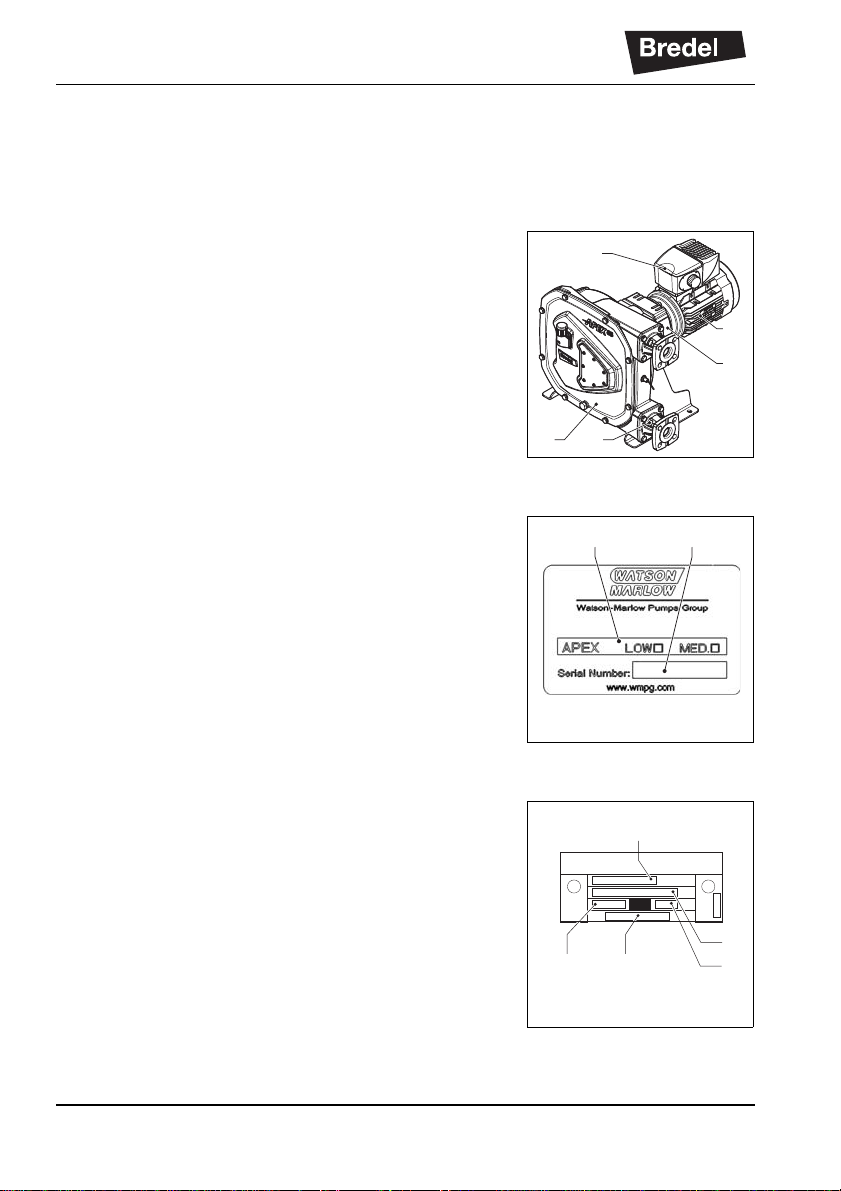
4.1.1 Identification of the product
The hose pump can be identified by identification plates
or stickers on:
A: Pumphead
B: Gearbox
C: Electric motor
D: Pump hose
E: Frequency controller (option)
4.1.2 Identification of the pump
The identification plate on the pumphead contains the
following data:
A: Pump type and rotor type (low or medium
pressure)
B: Serial number
4.1.3 Identification of the gearbox
The identification plate on the gearbox contains the
following data:
A: Article number
B: Serial number
C: Type number
D: Reduction ratio
E: Number of revolutions per minute
E
AD
C
B
BA
min-1
N
o
i
D A B
E
C

DESCRIPTION
15
4.1.4 Identification of the electric motor
The identification plate on the electric motor contains
the following data:
B: Serial number
C: Article number
D: Mains
E: Frequency
F: Speed
G: Power
H: Power factor
I: Current
4.1.5 Identification of the frequency controller
The identification of the Bredel Variable Frequency
Drive (VFD) can be found inside the VFD. Remove the
cover by loosening the two screws. The identification
sticker contains the following data:
A: Article number
B: Serial number
4.1.6 Identification of the pump hose
The identification sticker on the pump hose contains the
following data:
A: Pump type
B: Part code
C: Internal diameter
D: Type of material of inner liner
E: Remarks, if applicable
F: Maximum permissible working pressure
G: Production code
V
S
IP IK
Hz min-1 kW A
COS
C/h%
N
o
U
N
VP
Mf Nm
CF
o
D E F GH I
CB
LS serial number
sn20837003969
Bredel article number E384083
A
B
A
B
C
D
E
F
G

DESCRIPTION
16
4.2 Construction of the pump
A: Cover
B: Rotor
C: Pump hose
D: Pump housing
E: Supports
F: Gearbox
G: Electric motor
H: Frequency controller
A
D
C
E
G
E
F
H
B

DESCRIPTION
17
4.3 Operation of the pump
The heart of the pumphead consists of a specially
constructed pump hose (A) which lies against the inside
of the pump housing (B). The ends of the hose are
connected to the suction and discharge lines (C). A
bearing-mounted rotor (D) with two facing integral
pressing shoes (E) is in the center of the pumphead. It
rotates clockwise.
In phase 1 the lower shoe compresses the pump hose
by the rotational movement of the rotor, forcing fluid
through the hose. As soon as the shoe has passed, the
hose recovers to its original shape due to the
mechanical properties of the material and fluid is drawn
into the hose.
In phase 2 fluid is drawn through the hose by the
(continuous) turning motion of the rotor.
In phase 3, the second integral pressing shoe
compresses the pump hose. Due to the continuous
rotating movement of the rotor new fluid is sucked in
and fluid that is previously drawn in is pressed out by
the shoe. When the first shoe leaves the pump hose,
the second shoe has already occluded the pump hose
and fluid is prevented from flowing back. This method of
liquid displacement is known as the "positive
displacement principle".
AB ECD

DESCRIPTION
18
4.4 Pump hose
4.4.1 General
A: Extruded outer layer made of natural rubber
B: Four nylon reinforcement layers
C: Extruded inner liner
The pump hose liner material should be chemically
resistant to the product being pumped. For each pump
model various hose types are available. Choose the
most appropriate for your application.
The material of the inner liner of the pump hose
determines the hose type. Each hose type is marked by
a unique colour code.
Bredel pump hoses have been carefully machined to
achieve minimum tolerances in wall thickness. It is very
important to guarantee the correct compression of the
pump hose, because:
•When the compression is too high, it creates an
excessive load on the pump and pump hose,
which may reduce the life of the pump hose and
bearings.
•When the compression is too low, it cuts
capacity and causes backflow. Backflow
reduces the life of the pump hose.
B C
A
Hose type Material Colour code
NR Natural rubber Purple
NBR Nitrile rubber Yellow
EPDM EPDM Red
Consult your Bredel representative for
more detailed information about the chemi-
cal and temperature resistance of pump
hoses.

DESCRIPTION
19
4.4.2 Hose compression force adjustment
The compression force on the pump hose can be
adjusted by installing a rotor with a different dimension
between the tips of the integral pressing shoes. The
rotor is chosen to achieve an optimal life of the pump
hose for the intended use of the hose pump. Two rotor
sizes are available: a low-pressure rotor and a medium
pressure rotor.
Low-pressure rotors and medium-pressure rotors can
be recognized by a marked hole near the ‘M’ for
medium-pressure (A) or ’L’ for low-pressure (B) on the
rotor.
Refer to the table for the correct rotor per required
discharge pressure.
If you want to change the application of your hose
pump, contact your Bredel representative.
4.4.3 Lubrication and cooling
The pumphead is filled with Bredel Genuine Hose
Lubricant. This lubricant lubricates the shoes and
dissipates the heat generated by the movement of the
pressing shoes against the pump hose.
The lubricant is food grade. The user is responsible to
ensure the chemical compatibility of the lubricant with
the fluid to be pumped. Refer to § 11.1.4 for the
required quantity and NSF registration.
Refer to § 7.5 for the consequences of a hose failure.
B A
Discharge pressure Rotor size
0 - 400 kPa (58 psi) Low-pressure
0 - 800 kPa (116 psi)*
* Preferably 400 - 800 kPa (58 - 116 psi)
Medium-pressure
Consult your Bredel representative for
lubrication recommendations when operat-
ing the hose pump below 2 rpm.

DESCRIPTION
20
4.5 Gearbox
The hose pump types described in this manual use
helical gearbox units. Other gearbox types are available
as option. The gearboxes are fitted with a flange
connection. The standard fasteners are bolts, but studs
and nuts are packed separately for your convenience.
Refer to § 11.3 for specifications.
Refer to the documentation supplied with the gearbox
for installation and maintenance information. In case of
doubt, consult your Bredel representative.
4.6 Electric motor
The standard electric motor is a completely enclosed
three-phase asynchronous motor. The motor
connection must meet the local applicable regulations.
Refer to the documentation supplied with the electric
motor for installation and maintenance information. In
case of doubt consult your Bredel representative. Refer
to § 5.3.4 and § 6.1 for installation and connection
information.
4.7 Available options
The following options are available for the hose pump:
•High level float switch
•Revolution counter
•Medium- or low-pressure rotor (depending on
the discharge pressure)
•Frequency controller1
•Three hose types
•Special configuration for use in explosive
atmospheres
1 Refer to the supplier’s documentation and § 11.5.
This manual suits for next models
2
Table of contents
Other Bredel Industrial Equipment manuals

Popular Industrial Equipment manuals by other brands

Pakole
Pakole ZENIT CONDENSER Instructions for installation and servicing

LYSON
LYSON PREMIUM PC-03 instruction manual

tornos
tornos DECO 20a installation instructions

DEUTSCHE VAN RIETSCHOTEN & HOUWENS
DEUTSCHE VAN RIETSCHOTEN & HOUWENS R+H 200.551.01 Maintenance and operating manual

Hoffmann
Hoffmann GARANT VG Basic instruction manual

Mid-West Instrument
Mid-West Instrument 109 Series Installation and operating instructions


