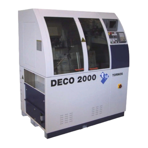
tornos DECO 20a User manual

INSTALLATION
300561 en
Printed in Switzerland Copyright (c)1999−2008
TORNOS SA
CH−2740 MOUTIER
http://www.tornos.ch
ΔATTENTION !
Before handling / operating the machine,
read first the SAFETY REGULATIONS !
DECO 20a / 26a
DECO 20e / 26e


INSTALLATION − DECO 20a / DEC0 26a / DECO 20e / DECO 26e
300561 en − 05/08 Chap. /3
These instructions are based on the information available at the moment of
their publication. Although the very best has been done to make them as com-
prehensive and precise as possible the instructions do not purport either to
cover all details of the hardware and software or to anticipate every con-
tingency.
TORNOS S.A. neither give any guarantee nor accept any liability for the
exactitude and the sufficiency of the information contained in this document.
The contents of the instructions remain the property of TORNOS S.A. who
reserve the right to modify, complete or correct them at any time.
The original language of the instructions to be referred to is French. The haz-
ards of misinterpreting the instructions can be considerably reduced by
following the training courses organized and offered by TORNOS S.A.
The CE-marking indicates conformity with the European standards
of safety, health, environment and protection.
TORNOS S.A.
Rue Industrielle 1 1 1
CH−2740 MOUTIER / SUISSE
Tél. 032 / 494 44 44
Fax 032 / 494 49 03
TORNOS TECHNOLOGIES
IBERICA
Pol. Ind. El Congost
Avda. St Julia, 206 Nave 8
E−08400 GRANOLLERS
Tel. (34) 93 846 59 43
Fax (34) 93 849 66 00
TORNOS−TECHNOLOGIES
DEUTSCHLAND
Karlsruher Str. 38
D−75179 PFORZHEIM
Tel. 07231/ 910 70
Fax 07231/ 910 750
TORNOS TECHNOLOGIES
ITALIA SRL Via Einstein, 24
I−20090 ASSAGO / MI
Tel. 02 45 77 17 01
Fax 02 45 70 16 48
TORNOS TECHNOLOGIES
FRANCE
Boîte postale 330
ST−PIERRE EN FAUCIGNY
F74807 LA ROCHE
S / FORON CEDEX
Tél. 04 50 038 333
Fax 04 50 038 907
TORNOS TECHNOLOGIES
US CORPORATION
70 Pocono Road PO. Box 325
BROOKFIELD CT 06804 / USA
Tel. (203) 775−4319
Fax (203) 775−4281
TORNOS TECHNOLOGIES UK Ltd
Tornos House
Whitwick Business Park Coalville
Leicestershire
LE67 4JQ
Tel. 01530 513100
Fax 01 530 814212

INSTALLATION − DECO 20a / DEC0 26a / DECO 20e / DECO 26e
300561 en − 05/08 Chap. /4
Differentiationof degrees of risk
These instructions indicate a number of safety measure symbols which
appear also on the machine and are intended to protect the user, his/her
effects and the environment from injuries and damage as applicable.
Below, you will find the safety symbols, their headings and definitions. Please,
read these first before you continue.
ΔDanger !
indicates a direct danger of death or serious injury.
ΔWarning !
indicates an object or action which may cause death or serious
injury.
ΔCaution !
indicates an object or action which may cause injury or serious
damage.
.Attention !
indicates incorrect actions or such that may cause damage.
⊗Prohibition !
indicates an action or operation prohibited because of evident or
alleged hazards.
⇒Info :
Gives information or comment related to safety.
Note :
Gives information unrelated to safety
Important Safety Indications
ΔWarning !
Read the instruction before operating the machine.
Should the user disregard the instructions of this manual, TORNOS SA
declines any liability whatsoever.
ΔAttention !
Certain maintenance works are absolutely necessary to ensure good
operation of the machine. They are given in the MAINTENANCE
SCHEDULE on the machine
(or see Instructions: OPERATION-MAINTENANCE).
.Attention !
TORNOS SA disclaims all responsibility for any modifications carried
out by the customer to the machine, and to its related equipment and
software, without agreement ratified by TORNOS SA.

INSTALLATION − DECO 20a / DEC0 26a / DECO 20a − 0018 & 0020 / DECO 26a − 0018 & 0020
5300561 en − 12/03
TABLE OF CONTENTS
1. GENERAL 1. . . . . . . . . . . . . . . . . . . . . . . . . . . . . . . . . . . . . . . . . . . . . . . . . . . . . . . . . . . . .
1.1 SAFETY MEASURES & DEVICES 1. . . . . . . . . . . . . . . . . . . . . . . . . . . . . . . . . . . . . . . . . . . . . . . . . . . .
1.2 STANDARD MACHINE DATA 1. . . . . . . . . . . . . . . . . . . . . . . . . . . . . . . . . . . . . . . . . . . . . . . . . . . . . . . . .
1.3 BARFEEDING REQUIREMENTS 2. . . . . . . . . . . . . . . . . . . . . . . . . . . . . . . . . . . . . . . . . . . . . . . . . . . . .
2. UNPACKING − CLEANING 1. . . . . . . . . . . . . . . . . . . . . . . . . . . . . . . . . . . . . . . . . . . . . .
2.1 PACKING LATHE FOR TRANSPORT 1. . . . . . . . . . . . . . . . . . . . . . . . . . . . . . . . . . . . . . . . . . . . . . . . .
2.1.1 Handling Equipment 1. . . . . . . . . . . . . . . . . . . . . . . . . . . . . . . . . . . . . . . . . . . . . . . . . . . . . . . . . . . . . . . . .
2.2 UNPACKING LATHE 1. . . . . . . . . . . . . . . . . . . . . . . . . . . . . . . . . . . . . . . . . . . . . . . . . . . . . . . . . . . . . . . .
2.3 CLEANING LATHE 1. . . . . . . . . . . . . . . . . . . . . . . . . . . . . . . . . . . . . . . . . . . . . . . . . . . . . . . . . . . . . . . . . .
2.3.1 Cleaning Lathe after Unpacking 1. . . . . . . . . . . . . . . . . . . . . . . . . . . . . . . . . . . . . . . . . . . . . . . . . . . . . . .
3. LOCATION & INSTALLATION 1. . . . . . . . . . . . . . . . . . . . . . . . . . . . . . . . . . . . . . . . . . .
3.1 FLOOR PLANS 1. . . . . . . . . . . . . . . . . . . . . . . . . . . . . . . . . . . . . . . . . . . . . . . . . . . . . . . . . . . . . . . . . . . . .
3.2 FLOOR LOCATION 1. . . . . . . . . . . . . . . . . . . . . . . . . . . . . . . . . . . . . . . . . . . . . . . . . . . . . . . . . . . . . . . . .
3.2.1 Removing Transport Locks 1. . . . . . . . . . . . . . . . . . . . . . . . . . . . . . . . . . . . . . . . . . . . . . . . . . . . . . . . . . .
3.3 FLOOR PLAN FOR DECO 20A 4. . . . . . . . . . . . . . . . . . . . . . . . . . . . . . . . . . . . . . . . . . . . . . . . . . . . . . .
3.3.1 Floor Plan for DECO 20a with Thrust Tube Operation Detail 5. . . . . . . . . . . . . . . . . . . . . . . . . . . . . .
3.3.2 Floor Plan for DECO 20a with Chip Conveyor 6. . . . . . . . . . . . . . . . . . . . . . . . . . . . . . . . . . . . . . . . . . .
3.3.3 Floor Plan for DECO 20a with Barfeeder SSF−226 7. . . . . . . . . . . . . . . . . . . . . . . . . . . . . . . . . . . . . .
3.3.4 Floor Plan for DECO 20a with Feed Tube LNS 8. . . . . . . . . . . . . . . . . . . . . . . . . . . . . . . . . . . . . . . . . .

INSTALLATION − DECO 20a / DEC0 26a / DECO 20a − 0018 & 0020 / DECO 26a − 0018 & 0020
6300561 en − 12/03
3.4 FLOOR PLAN FOR DECO 26A 9. . . . . . . . . . . . . . . . . . . . . . . . . . . . . . . . . . . . . . . . . . . . . . . . . . . . . . .
3.4.1 Floor Plan for DECO 26a with Thrust Tube Operation Detail 10. . . . . . . . . . . . . . . . . . . . . . . . . . . . . .
3.4.2 Floor Plan for DECO 26a with Chip Conveyor 11. . . . . . . . . . . . . . . . . . . . . . . . . . . . . . . . . . . . . . . . . . .
3.4.3 Floor Plan for DECO 26a with Barfeeder SSF−532 12. . . . . . . . . . . . . . . . . . . . . . . . . . . . . . . . . . . . . .
3.4.4 Floor Plan for DECO 26a with Feed Tube LNS 13. . . . . . . . . . . . . . . . . . . . . . . . . . . . . . . . . . . . . . . . . .
3.4.5 Floor Preparation 14. . . . . . . . . . . . . . . . . . . . . . . . . . . . . . . . . . . . . . . . . . . . . . . . . . . . . . . . . . . . . . . . . . .
3.4.6 Fixing Lathe on the Floor 14. . . . . . . . . . . . . . . . . . . . . . . . . . . . . . . . . . . . . . . . . . . . . . . . . . . . . . . . . . . . .
3.5 PREPARING LATHE FOR TRANSPORT 15. . . . . . . . . . . . . . . . . . . . . . . . . . . . . . . . . . . . . . . . . . . . . . .
3.5.1 Mechanical Locking of Lathe’s Mobile Units 15. . . . . . . . . . . . . . . . . . . . . . . . . . . . . . . . . . . . . . . . . . . .
3.6 ELECTRIC INSTALLATION 16. . . . . . . . . . . . . . . . . . . . . . . . . . . . . . . . . . . . . . . . . . . . . . . . . . . . . . . . . .
3.6.1 Installation Characteristics 17. . . . . . . . . . . . . . . . . . . . . . . . . . . . . . . . . . . . . . . . . . . . . . . . . . . . . . . . . . .
3.7 ELECTRIC CONNECTION DECO 20A / 26A 18. . . . . . . . . . . . . . . . . . . . . . . . . . . . . . . . . . . . . . . . . . .
3.7.1 Connecting TORNOS Autotransformer 19. . . . . . . . . . . . . . . . . . . . . . . . . . . . . . . . . . . . . . . . . . . . . . . . .
3.7.2 Connecting Non-TORNOS Autotransformer 21. . . . . . . . . . . . . . . . . . . . . . . . . . . . . . . . . . . . . . . . . . . .
3.8 ELECTRIC CONNECTION DECO 20A − 0018 − 0020 / DECO 26A − 0018 − 0020 22. . . . . . . . . .
3.8.1 Connecting TORNOS Autotransformer 23. . . . . . . . . . . . . . . . . . . . . . . . . . . . . . . . . . . . . . . . . . . . . . . . .
3.8.2 Connecting Non-TORNOS Autotransformer 24. . . . . . . . . . . . . . . . . . . . . . . . . . . . . . . . . . . . . . . . . . . .
3.9 CONNECTING BARFEEDER AND CHIP CONVEYOR 25. . . . . . . . . . . . . . . . . . . . . . . . . . . . . . . . . .
3.10 PNEUMATICS INSTALLATION 26. . . . . . . . . . . . . . . . . . . . . . . . . . . . . . . . . . . . . . . . . . . . . . . . . . . . . . .
3.10.1 Air Quality Specification 26. . . . . . . . . . . . . . . . . . . . . . . . . . . . . . . . . . . . . . . . . . . . . . . . . . . . . . . . . . . . . .
3.10.2 Pneumatical connection 26. . . . . . . . . . . . . . . . . . . . . . . . . . . . . . . . . . . . . . . . . . . . . . . . . . . . . . . . . . . . .
4. INDEX 1. . . . . . . . . . . . . . . . . . . . . . . . . . . . . . . . . . . . . . . . . . . . . . . . . . . . . . . . . . . . . . . .
4.1 INDEX: SPARE PARTS
Replacement parts are to be found in the following three books :
− Instructions for use / Servicing and / or Machine Equipment and /or Options and their tooling. 1

INSTALLATION − DECO 20a / DEC0 26a / DECO 20e / DECO 26e
300561 en − 05/08 Chap. 1.2 /1
1. GENERAL
1.1 SAFETY MEASURES & DEVICES
These are described in the Instructions 300480: SAFETY REGULATIONS
DECO 2000.
ΔWarning !
Failure to comply with the safety regulations may
cause serious accidents.
1.2 STANDARD MACHINE DATA
Feature Notes DECO 20a
data DECO 26a
data
Length : 2270 mm 2270 mm
Width : 1550 mm 1550 mm
Height : without signal lamp 2220 mm 2220 mm
Enclosure weight : approx. 650 kg 650 kg
Full weight : approx. 3300 kg 3750 kg
Specific load : per surface unit 12.0 daN/cm213.9 daN/cm2
⇒Note :
For more details, consult your operating instructions entitled :
OPERATION & MAINTENANCE.
⇒Note :
For more details, consult your operating instructions entitled :
MACHINE EQUIPMENT.
DETAILED DIMENSIONS
− See Para. LOCATION AND INSTALLATION

INSTALLATION − DECO 20a / DEC0 26a / DECO 20e / DECO 26e
300561 en − 05/08 Chap. 1.3 /2
1.3 BARFEEDING REQUIREMENTS
BARFEEDING DESCRIPTION
− For regular use, your DECO 20a / DECO 26a lathe must be equipped with
a stock tube / feeder with pusher.
− The tube / feeder is a unit independent of the lathe and has its own
controls.
− The control panel with manual controls of the tube / feeder is ergonomi-
cally arranged to conform to your DECO 20a / DECO 26a.
ΔCaution !
For impeccable operation of the BARFEEDER−LATHE assembly
TORNOS have issued instructions with the characteristics & functions
required for the feeder−lathe interface. The instructions are entitled :
INTERFACE SPECIFICATIONS FOR STOCK TUBE OR BARFEEDER
These specifications must be strictly complied with to avoid malfunc-
tioning of the bar feeding system, which might be imputed to the lathe.
TORNOS declines any liability whatsoever, should a damage or acci-
dent be imputed to a tube / feeder which do not conform to the said
specifications &/or standards in force.
BARFEEDER LOCATION / INSTALLATION
− See your instructions: INTERFACE SPECIFICATIONS FOR INSTALLA-
TION OF STOCK TUBE OR BARFEEDER
− See also Para.: Connecting Barfeeder and Chip Conveyor, below.

INSTALLATION − DECO 20a / DEC0 26a / DECO 20e / DECO 26e
300561 en − 05/08 Chap. 2.3.1 /1
2. UNPACKING − CLEANING
2.1 PACKING LATHE FOR TRANSPORT
What to do ? Notes
− Pack in a case ...
or
− Pack on a board ...
... for overseas or special trans-
ports.
... for continental transport.
Note : The invoiced packing items are property of the customer.
2.1.1 Handling Equipment
No handling equipment is provided for single-spindle automatics.
2.2 UNPACKING LATHE
Note :
Whenever you move the lathe about, proceed according to the
TRANSPORT INFO Sheet 300551 included in the machine’s docu-
mentation.
What to do ? Notes
− Pull out nails from the cover and
then from the walls of the case.
− Remove the vacuum-packing
plastic.
− Remove the wooden wedges
and ropes ... ... that hold various items.
2.3 CLEANING LATHE
2.3.1 Cleaning Lathe after Unpacking
Note :
For certain destinations the machine is rust-protected.
What to do ? Notes
− Wash carefully with gasoline or
petroleum-soaked cloth all rust-
protected surfaces.
ΔAttention !
Wash on well ventilated prem-
ises only to avoid inhaling toxic
vapors !
ΔCaution !
Do not damage or disrupt any-
thing.
ΔAvoid using compressed air and
substances that could damage
plastic materials.

INSTALLATION − DECO 20a / DEC0 26a / DECO 20e / DECO 26e
300561 en − 05/08 Chap. 2.3.1 /2
>>>

INSTALLATION − DECO 20a / DEC0 26a / DECO 20e / DECO 26e
300561 en − 05/08 Chap. 3.2.1 /1
3. LOCATION & INSTALLATION
3.1 FLOOR PLANS
DECO 20a See figures in Para. 3.3.
DECO 26a See figures in Para. 3.4.
3.2 FLOOR LOCATION
− Take into account the dimensions of various options that you can attach
to the machine (bar feed tube, barfeeder, conveyor, equipment for long
parts, for deep drilling, etc.) because the floor plan shows the basic
machine equipment only.
− Arrange a barfeeder according to a particular bar feeding method.
− See your instructions:
INTERFACE SPECIFICATIONS FOR INSTALLATION OF STOCK TUBE
OR BARFEEDER
ΔWarning !
Spacing between the lathe and the barfeeder must be too close for
fingers to get in between and suffer injury.
3.2.1 Removing Transport Locks
What to do ? Notes
− Remove the wooden wedges
and ropes that hold various items
in place:
oil tank, chip pan, manipulator,
hatches
− Take down the yellow pieces
locking the frontwork unit and the
pickoff spindle:
See Fig. 306009f1 & 306009f2.
Z3 & Z4 axes
− Unscrew the yellow M8x60 screw
from the front of the vertical sup-
port:
The screw locks the part catching
manipulator. Put away the locking
pieces for possible use in future.

INSTALLATION − DECO 20a / DEC0 26a / DECO 20e / DECO 26e
300561 en − 05/08 Chap. 3.2.1 /2
306009f1
25
023
003
021
0
For DECO VERSION 0018−0020
306009f2v2

INSTALLATION − DECO 20a / DEC0 26a / DECO 20e / DECO 26e
300561 en − 05/08 Chap. 3.2.1 /3
306009f2
240
220
040
.Caution !
Do not remove the transport locks until the lathe is properly located.
SPARE PARTS − TRANSPORT LOCKS
Item Designation Axis / Item
to lock
030 562360 Yellow rod Z4
040 562361 Yellow piece Z3
210 020200 Screw M6x20 Z4
220 213031 Screw M10x35 Z3
230 501100 Nut M10 Z4
240 580076 Washer 10.5x20 Z3
250 580449 Screw M10x40 Z4
− 821953 Rod dia. 6 / 8 mm Spindle, etc.
090 565278 Yellow piece Bridage Z3 for trans-
port of DECO VER-
SION 0018−0020
200 216989 Screw M6x12 Bridage Z3 for tran-
sport of DECO VER-
SION 0018−0020

INSTALLATION − DECO 20a / DEC0 26a / DECO 20e / DECO 26e
300561 en − 05/08 Chap. 3.3 /4
3.3 FLOOR PLAN FOR DECO 20a
199223f6
E
F
E
E

INSTALLATION − DECO 20a / DEC0 26a / DECO 20e / DECO 26e
300561 en − 05/08 Chap. 3.3.1 /5
3.3.1 Floor Plan for DECO 20a with Thrust Tube Operation Detail
199223f7

INSTALLATION − DECO 20a / DEC0 26a / DECO 20e / DECO 26e
300561 en − 05/08 Chap. 3.3.2 /6
3.3.2 Floor Plan for DECO 20a with Chip Conveyor
199223f10

INSTALLATION − DECO 20a / DEC0 26a / DECO 20e / DECO 26e
300561 en − 05/08 Chap. 3.3.3 /7
3.3.3 Floor Plan for DECO 20a with Barfeeder SSF−226
199223f9

INSTALLATION − DECO 20a / DEC0 26a / DECO 20e / DECO 26e
300561 en − 05/08 Chap. 3.3.4 /8
3.3.4 Floor Plan for DECO 20a with Feed Tube LNS
199223f8

INSTALLATION − DECO 20a / DEC0 26a / DECO 20e / DECO 26e
300561 en − 05/08 Chap. 3.4 /9
3.4 FLOOR PLAN FOR DECO 26a
199225f4
E
F
E
E

INSTALLATION − DECO 20a / DEC0 26a / DECO 20e / DECO 26e
300561 en − 05/08 Chap. 3.4.1 /10
3.4.1 Floor Plan for DECO 26a with Thrust Tube Operation Detail
199225f5
This manual suits for next models
3
Table of contents
Other tornos Industrial Equipment manuals
