DEUTSCHE VAN RIETSCHOTEN & HOUWENS R+H 200.551.01 Operating and maintenance manual
Installation:
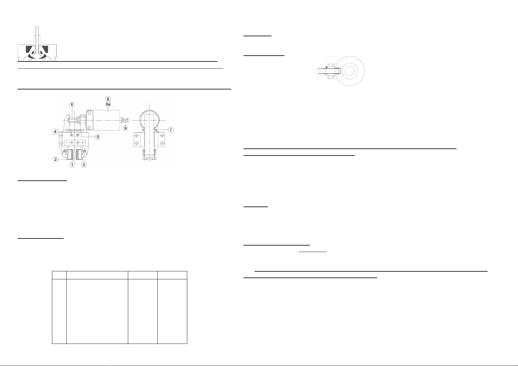
Einbaulage:Bremscheibenachse horizontal,Bremszange in Position 3 Uhr bzw.
9 Uhr,jeweils +/- 15 °.Bei Abweichungen dieser Einbaulage Hersteller kontaktieren!
Einbaubeispiel:
Die Bremszange ist so anzusetzen,daß die Bremsbeläge planparallel zur Bremsscheibe liegen
und deren äußerer Durchmesser einen Hüllkreis über die Bremsbelagfläche bildet.
Die Bremshebel sollten auf den Mittelpunkt der Bremsscheibe gerichtet sein,damit die beim
Bremsen auftretende Umfangskraft senkrecht über die formschlüssige Verbindung vom
Bremsbelag auf den Bremshebel übertragen werden kann. Das Gehäuse ist mittels
Schrauben M12-8.8 fest mit dem Unterbau zu verschrauben.
Den Betätigungszylinder mit einem flexiblen Schlauch an das Hydrauliknetz anschließen und mit
Druck beaufschlagen.
Achtung:Gegen unbeabsichtigtes Betätigen sichern, wenn die „Montagehilfe (9)“
bereits entfernt wurde. Verletzungsgefahr!
Der „Stößel (8)“ ist solange herauszudrehen,bis sich bei fest montiertem Betätigungszylinder ein
Luftspalt zwischen Bremsbelag und Bremsscheibe von 0,5 - 1 mm pro Seite einstellt.
Die Hydraulikzuführung ist so zu befestigen,daß sie gegen Beschädigungen durch äußere
Einflüsse geschützt ist und die Bremshebel frei beweglich bleiben.
Achtung: Bedingt durch den Verschleiß der Bremsbeläge vergrößert sich der
Hub des Betätigungszylinders. Spätestens bei einem Hub von 12 mm ist der
Luftspalt neu einzustellen. Der konstruktive Hub des Zylinders ist auf 18 mm begrenzt!
Wartung:
Alle Stellen,an denen eine Relativbewegung stattfindet,sollten in Verbindung mit dem Wechsel der
Bremsbeläge nachgeschmiert werden werden.
Schmierstoffempfehlung:Schmierfett auf Molybdänsulfid-Basis
Bei Betrieb im Freien oder in aggressiver Umgebung wird eine vierteljährliche
Kontrolle der Bremszange empfohlen.
Wechsel der Bremsbeläge:
Spätestens bei einer sichtbaren Restbelagstärke von 2 mm sind die
Bremsbeläge zu wechseln!
1. Betätigungszylinder mit Druck beaufschlagen,gegen unbeabsichtigtes Betätigen sichern
und von der Bremszange lösen.Verletzungsgefahr!
2. Stößel des Betätigungszylinders ganz hineindrehen.
3. Haltefeder entfernen.
4. Bremsbelag gegen die Bremsscheibe drücken,bis er aus den Rezeß des Bremsschuhs
heraus ist.
5. Bremsbelag tangential zur Bremsscheibe entfernen.
6. Neuen Bremsbelag einsetzen und in den Sitz des Bremsschuhs drücken.
7. Haltefedern einsetzen.
8. Vorgang 1. bis 7. beim zweiten Bremsbelag wiederholen.
9. Luftspalt zwischen Bremsscheibe und Bremsbelag neu einstellen (siehe oben).
10. Betätigungszylinder festziehen.Anzugsmoment der Muttern = 60 Nm.
11. Luftspalt einstellen wie oben beschrieben.
DEUTSCHE VAN RIETSCHOTEN & HOUWENS GMBH
D-30179 Hannover♦Junkersstraße 12♦Telefon:0511-37207-0♦Fax:0511-37207-77
Wartungs- und Betriebsanleitung Bremszange R+H 200.551.01 , Artikel-Nr.: 11292
Wichtiger Hinweis:Diese Bremszange darf nur für den vorgesehenen Einsatzzweck
verwendet werden.Bei Mißbrauch besteht Verletzungsgefahr!
Attention: Spring inside the thruster is always under pressure, do not open the
thruster, serious risk of injury!
In event of malfunction the thruster have to send to main plant for
repairing (detailed disassembling instructions available on request).
Technische Daten:
Federbetätigt,hydraulisch geöffnete Bremszange,
Bremskraft: 7250 N, min. Öffnungsdruck 65 bar, max. Betriebsdruck 160 bar
Gewicht: 16,0 kg
Pos. Benennung Anzahl Art.-Nr.
1 Bremsbelag 2 10775
2 Haltefeder 2 10268
3 Schuhhaltefeder 2 10521
4 Ankerblech 1 10942
5 Rückstellfeder 2 10883
6 Betätigungszylinder 1 11256
6a Kolbendichtung
Stößeldichtung
1
1
11276
11275
7 Rückstellfeder 1 10270
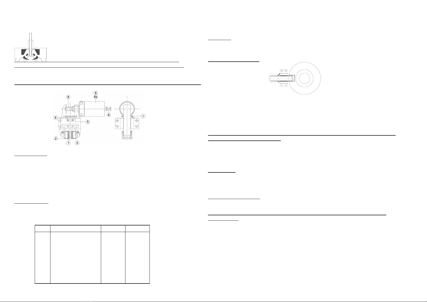
Installation:
Please note that the axle of the brake disc has to be in horizontal position,the calliper
in 9 o'clock resp. 3 o'clock position +/- 15 °.
If this can not be kept,please contact manufacturer!
Example of installation:
The calliper has to be installed so that the brake pads are in parallel with the disc and that the
outer diameter of the disc will completely contact the pads.The brake levers should show to
the center of the disc so that the braking force will go rectangular into the base of the calliper.
The base has to be tightened by using screws M12-grade 8.8. Install the hydraulic line to the
thruster by means of a flexible hose in that way that the brake levers can freely move.Supply
hydraulic pressure to the thruster.
Caution:Secure hydraulic supply from switching off, if mounting aid “assy (9)” already
has been removed. Risk of injury!
Screw the “push rod (8)” of the thruster that far out that there will be an airgap between the
brake pad and the disc of 0.5 - 1.0 mm each side when the thruster is tightened to the brake calliper.
Caution: Due to pad wear the stroke of the thruster increases during operation.
Not later than a stroke of approximately 12 mm is reached, the air gap has to be re-
adjusted. The designed stroke of the thruster is limited to 18 mm.
Maintenance:
All moving parts should be regreased when changing the brake pads.
Type of grease:Molybdenium Sulfide bases grease
At outdoor operation or in aggressive ambients an inspection of the calliper every 3 months
is recommended.
Changing the brake pads:
Latest at a visible thickness of 2 mm the brake pads have to be changed!
1. Switch on the hydraulic supply to the thruster and secure against switching off!
Risk of injury!
2. Remove thruster from calliper and screw the push rod of the thruster completely into the
thruster.
3. Remove retaining spring.
4. Push the brake pad towards the disc until it comes off the recess.
5. Remove the pad in tangential direction.
6. Insert new brake pad and press into the recess of the shoe.
7. Install retaining spring.
8. Carry out step 2 to 7 on second pad.
9 .Adjust the air gap between brake pad and disc to 0.5 mm when the thruster is tightened
to the calliper by turning the push rod out of the thruster .
10. Tighten the thruster.Tightening torque of nuts = 60 Nm.
11. Adjust airgap as described above.
DEUTSCHE VAN RIETSCHOTEN & HOUWENS GMBH
D-30179 Hannover♦Junkersstraße 12♦Telefon:0511-37207-0♦Fax:0511-37207-77
Maintenance- and Operating Manual Disc Brake Type R+H 200.551.01 , Part-No.: 11292
Important Hint:This Disc Brake must only be used for that purpose it is designed for.
Not observing this hint can cause serious injury to operators!
Attention: Spring inside the thruster is always under pressure, do not open the
thruster, serious risk of injury!
In event of malfunction the thruster have to send to main plant for
repairing (detailed disassembling instructions available on request).
Technical Datas:
Spring applied , hydraulically released Disc Brake,
Braking force:7250 N , min. operating pressure 65 bar , max. operating pressure 160 bar
Weight: 16.0 kg
Pos. Designation Quantity Part.-Nr.
1 Brake pad 2 10775
2 Retaining spring 2 10268
3 Shoe retaining spring 2 10521
4 Anchor plate 1 10942
5 Tension spring 2 10883
6
6a
Thruster
Piston seal
Push rod seal
1
1
1
11256
11276
11275
7 Tension spring 1 10270
This manual suits for next models
1
Table of contents
Languages:


