Mid-West Instrument 109 Series User manual
Mid-West
®
Instrument
Installation and Operating Instructions -
Model 109 Series
B
ulletin No: IM
1
09
/1
8
Supersedes IM109/01
F
1. Safety
Before installing verify compatibility to the process
media and temperature in contact with the wetted
parts. Incompatible media and / or operation at
temperature extremes can cause premature
degradation of materials which could result in
safety risk to personnel.
Verify the selected pressure range (differential
pressure and working pressure) are within
specification for your application.
arning! Remaining media may result in a
risk to personnel, environment etc.
Use sufficient precautionary
measures when removing and
transporting the product.
1.1
Intended use: The differential pressure gauges
are used for monitoring differential pressures in
industrial applications. The manufacturer shall not
be liable for any claims if the product is used in
applications contrary to the intended use.
1.2
Personnel: Personnel installing and putting this
instrumentation into service shall be suitably trained
and qualified in accordance with local codes,
practices and regulations.
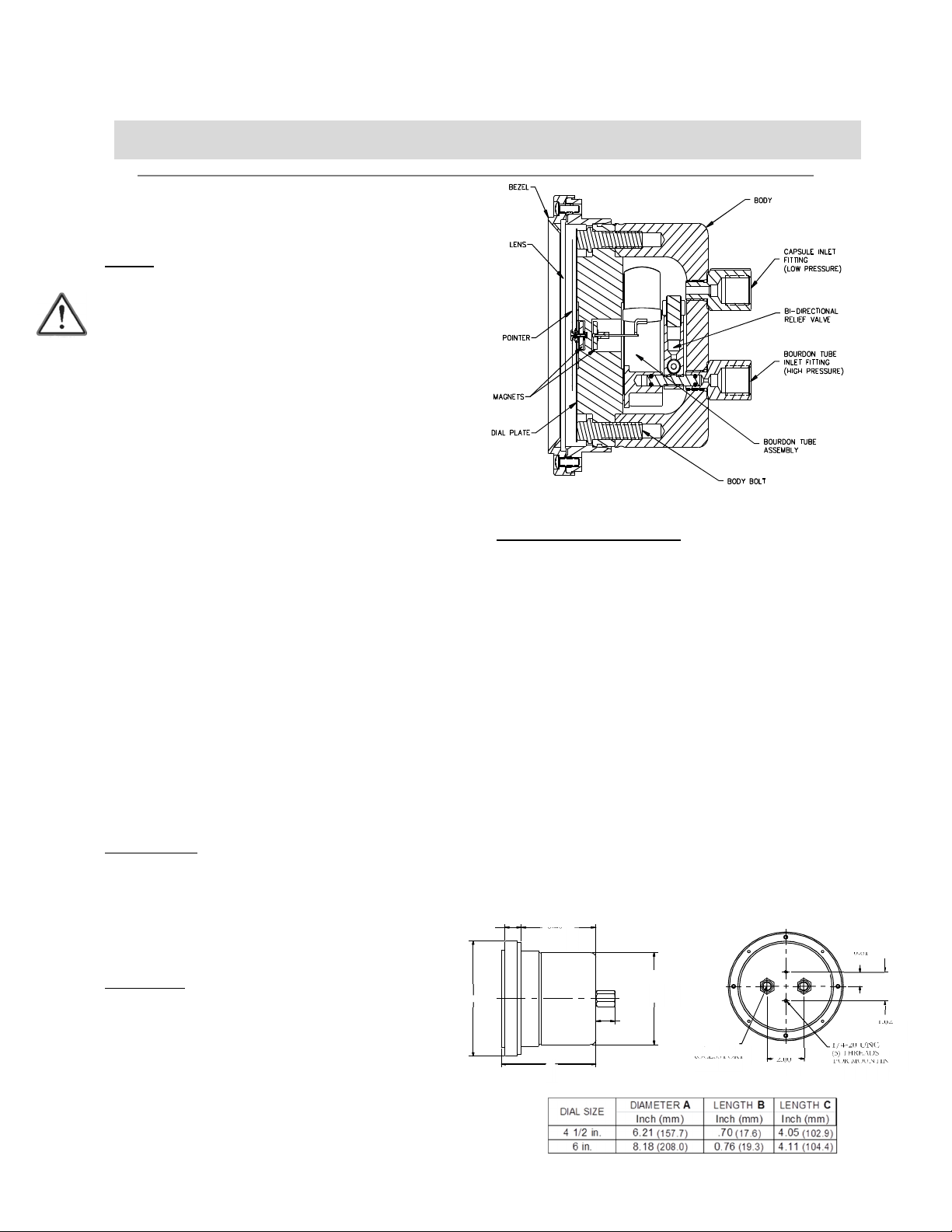
PRODUCT DESCRIPTION
The Model 109 is a precision differential pressure
gauge capable of wor ing in systems requiring medium to
high differential pressure readout. A test quality bourdon
tube assembly is used to sense the differential pressure.
The assembly is encapsulated in a high pressure chamber
that is fitted with a pressure connection to the inside of the
bourdon tube and a second connection to the pressure
chamber.
The output shaft of the bourdon tube and gauge
movement is magnetically coupled through the solid wall
of the pressure chamber to a sensitive jeweled pointer
shaft in the dial housing outside the chamber. The
bourdon tube is protected against over-range, in either
direction, to the rated wor ing pressure by a bi-directional
relief valve.
5.00
.82
3.20
[81.3 mm]
[20.9 mm]
[126.5 mm]
B
C
2.00
[50.8 mm]
1/4-20 UNC
(5) THRE DS
FOR MOUNTING
(2) PL CES
1/4 NPT
PROCESS PORT
(2) PL CES
1.62
[41.3 mm]
0.81
[20.6 mm]
HI LO
MODEL 109
LENGTH C
Installation and Operating Instructions
-
Model
1
09
Series
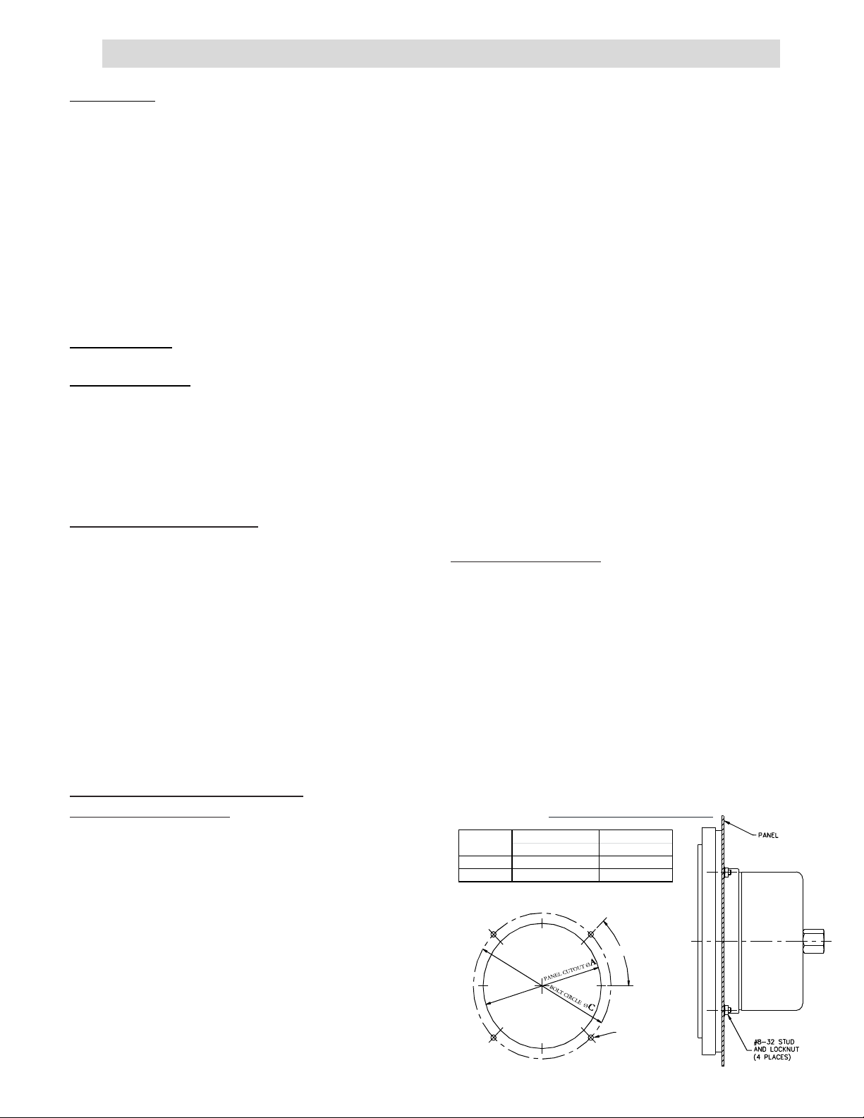
PANEL CUTOUT
A
BOLT CIRCLE
C
Inch (mm) Inch (mm)
4 1/2 in. 5.30
(134.6)
5.63
(143.0)
6 in. 6.50
(165.1)
7.00
(177.8)
DIAL SIZE
INSPECTION
Before installation chec the nameplate on each
instrument against the receiving paperwor and the
intended application for correct part number, materials of
construction, wor ing pressure, dial range, etc. If
equipped with switches, chec electrical rating, type of
enclosure, etc. Inspect for shipping damage and, if
damaged, report it immediately.
NOTE - Before attem ting re airs contact your local
Mid-West Re resentative or our factory. Failure to do
so will void any warranty.
INSTALLATION
1. CONNECTIONS
(2) ¼”FNPT pressure connections (fittings) are provided
on the bac of the gauge body as standard, but chec
paperwor for connections ordered. They are identified
as “HIGH” and “LOW” for high pressure and low
pressure. Be sure that the high gets connected to the
high and the low to the low side of your system.
2. INSTRUMENT LOCATION
On liquid service the instrument should be located below
the process connections to facilitate self-bleeding and on
gas service it should be located above the process
connections to promote self-draining. If the process
contains particulates, “pigtail” loops or drop legs
(manometer “U-tube” configuration) in the tubing will
minimize the possibility of the particulates migrating into
the instrument.
NOTE: ON LIQUID APPLICATIONS, UNEQUAL
LIQUID HEADS ON THE HIGH OR LOW SIDE
WILL RESULT IN AN INACCURATE
DIFFERENTIAL PRESSURE INDICATION.
3. INSTRUMENT INSTALLATION
RECOMMENDATIONS
Model 109 is calibrated and tested prior to shipment and
is ready for immediate installation. Use of the following
installation procedures should eliminate potential
damage and provide optimum trouble-free operation.
Rapid pressurization can cause severe damage to the
sensing element in pressure instruments. Rapid pressure
change (either increase or decrease) can be described as
a change in pressure occurring fast enough to drive an
instrument full scale in less than one second.
Most better quality instruments have over-range
protection built-in but they are mechanical in design and
cannot be relied upon to react in time to protect the
instrument against a rapid change in pressure.
The simplest method to avoid this problem is by
installation and proper use of a 3-valve manifold. Open
the equalizer valve prior to opening one or both of the
bloc valves to insure pressure is applied simultaneously
to both sides of the sensing element.
If a 3-valve manifold is not used, protection can be
provided by installation of Mid-West Model 150
snubbers to both sides of the instrument. This unit
provides an infinitely adjustable cho e valve and an
excess flow ball chec . The ball chec is designed not to
shut off completely but will restrict flow during sudden
changes in pressure while bleeding pressure to the
instrument, preventing sudden surges from being
transmitted to the instrument.
Refer any questions regarding these recommended
procedures to the local Mid-West representative in
your area or our factory in Sterling Heights, Michigan,
U.S.A.
4. PANEL MOUNTING
The Model 109 is designed for mounting through the
front of the instrument panel and is normally
provided with a panel mounting it. The it consists
of (4) panel mounting studs and nuts.
Ma e the cutouts as indicated in (Fig. 1). Insert the
(4) panel mounting studs, finger tight, into the metal
inserts located in the rear of the bezel.
Insert the gauge through the panel, aligning the
panel mounting studs with the holes in the panel.
Install the #8-32 nuts onto the studs and tighten
securely.
MODEL 109 PANEL CUT-OUT
DIMENSIONS
Ø 0.19 (4.7)
(4 HOLES)
45°

Installation and Operating Instructions
-
Model
1
09
Series
5. PIPE MOUNTING
If specified, your Model 109 will have a pipe mounting it
installed. This provides for mounting on a 2” vertical or
horizontal pipe. See below for details.
6. WALL MOUNTING
If specified, your Model 109 will have a wall mounting it
installed. This provides for mounting on a panel or wall.
See below for details.
TROUBLE
SHOOTING
1. Gauge does not indicate differential
A. Chec for proper hoo up, high to “HIGH” and
low to “LOW”
B. Ma e certain bloc valves are open and, if using
a 3-valve manifold, that the equalizer (balance)
valve is closed.
C. If A & B chec out correctly, loosen or
disconnect the high pressure line to determine if
there is pressure to the instrument.
D. If there is pressure to the instrument, chec to
determine that there is differential across the
unit being monitored. If so, contact the factory
for assistance and/or an “RGA” (return goods
authorization) number to return the instrument
for repair or replacement
2. Indicating ointer off zero. (With block valves
closed, or no system differential)
A. Tap gauge lightly.
B. Make certain block valves are closed and
equalizer valve is open.
C. If A & B do not correct the “off zero”
condition, remove the bezel and lens
assembly by removing the (4) bezel
screws. Slightly loosen the “phillips head”
screw, located in a slot in the dial, in the
lower left dial area at about “7:30”. Rotate
the dial until “zero” is under the pointer by
use of any pointed object inserted in one
of the small notches in the top and bottom
of the dial. Retighten the “phillips head”
screw and reinstall the bezel and lens
assembly.
Recalibration and/or Re air
1. If recalibration or repair is required, secure an
“RGA” (returned goods authorization) number
from Mid- West Instrument and return instrument
to the factory.
2. If (1) is not practical we recommend you discuss
your problem with one of our customer service
representatives and request a “technical service”
manual. Please have both the model and serial
numbers available before calling.
2 INCH PIPE MOUNT (FOR
VERTIC L OR HORIZONT L PIPE)
Other Mid-West Instrument Industrial Equipment manuals


