SPINEA G Series User manual

OPERATION MANUAL

2
Table of contents
1 General Information........................................................................................................................ 3
1.1 Introduction............................................................................................................................. 3
1.2 Use of the reducer................................................................................................................... 3
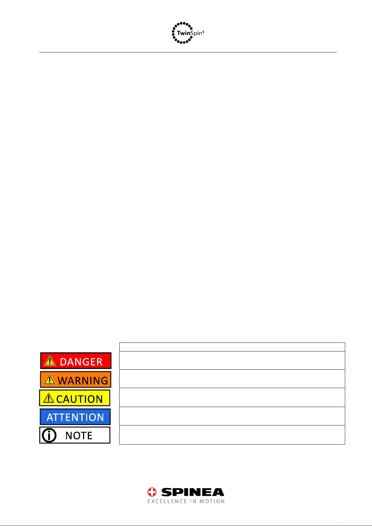
1.3 Terminology and types of alerts.............................................................................................. 3
2 Safety instructions........................................................................................................................... 4
2.1 General inustrctions................................................................................................................ 4
2.2 Installation of the reducer....................................................................................................... 4
2.3 Operation of the reducer ........................................................................................................ 5
2.4 Disposal ................................................................................................................................... 6
2.5 EU Directive 2006/42/EC......................................................................................................... 6
3 Product Description......................................................................................................................... 7
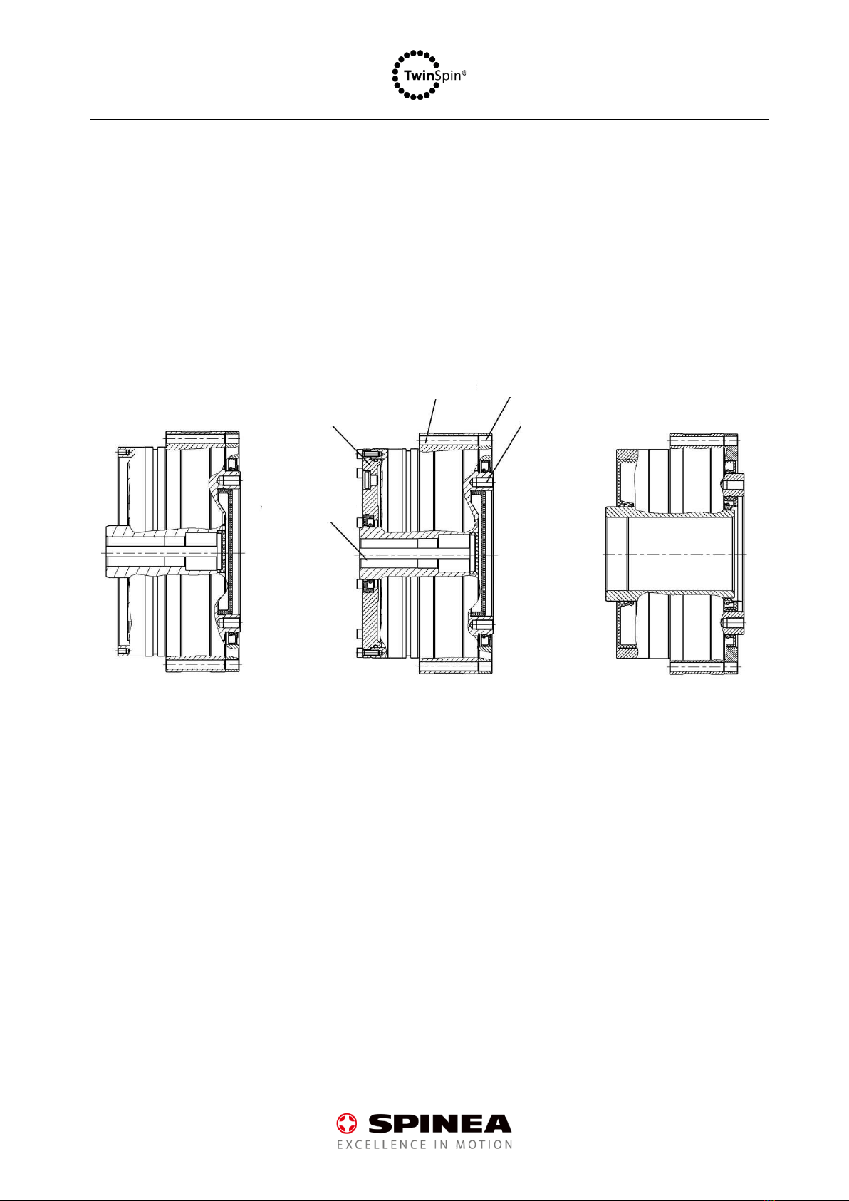
3.1 Reducer versions ..................................................................................................................... 7
4 Chapter Mounting Reducers in Applications................................................................................. 10
4.1 Motor flanges........................................................................................................................ 10
4.2 Bolts and tightening torque for mounting reducers............................................................. 11
4.3 Sealing components for sealed reducers .............................................................................. 13
4.4 Permissible input shaft load.................................................................................................. 13
4.5 Installation of TwinSpin reducers.......................................................................................... 14
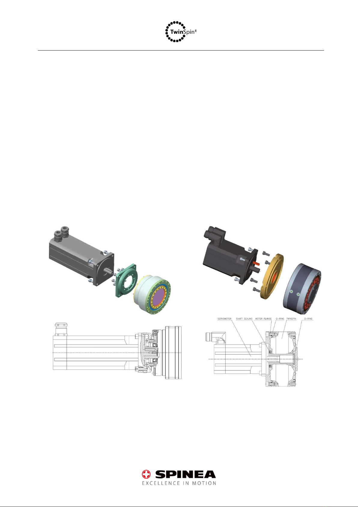
4.5.1 Assembly with direct connection to the motor with the keyway..................................... 16
4.5.2 Mounting with adapter (splined or keyway) with smooth shaft motor ........................... 17
4.5.3 Assembly with coupling..................................................................................................... 18
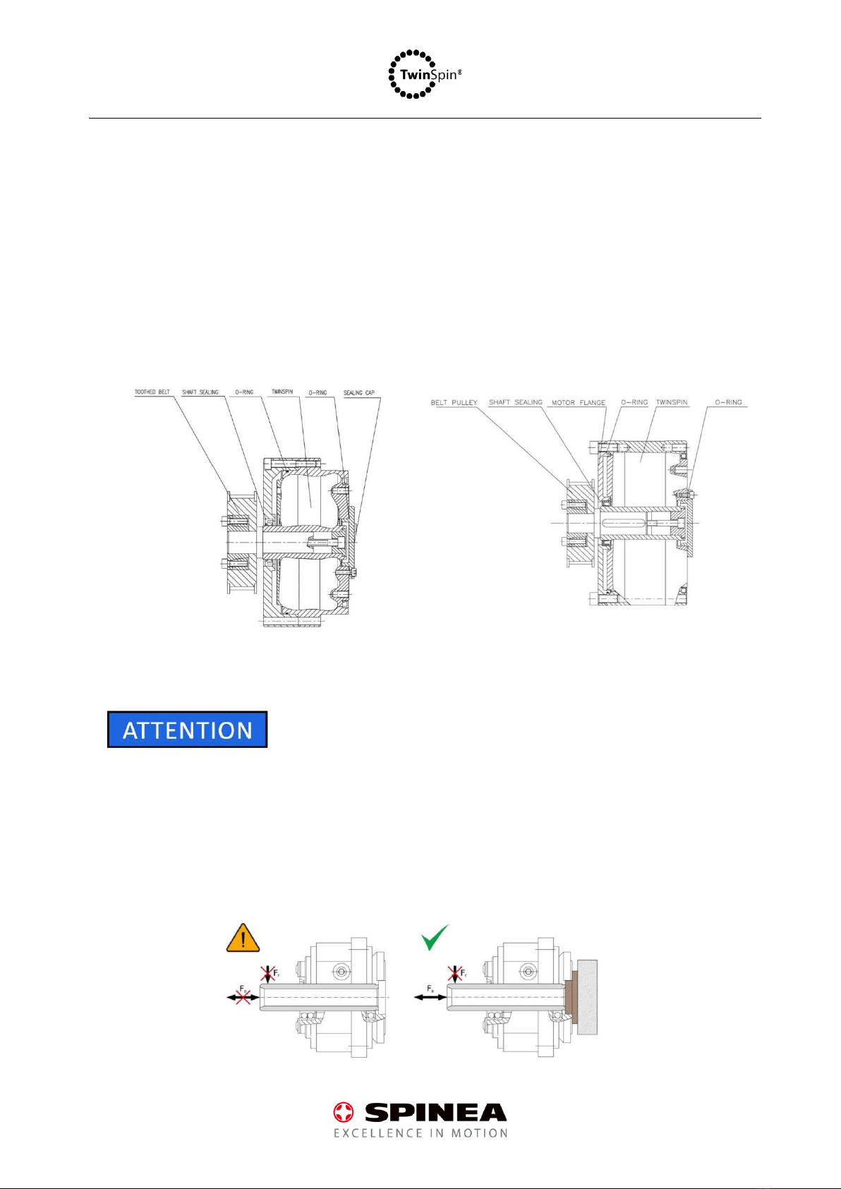
4.5.4 Mounting with pulley ........................................................................................................ 19
4.5.5 Specific installation warnings............................................................................................ 19
5 Lubrication of reducers ................................................................................................................. 20
6 Storage and transport ................................................................................................................... 21
7 Warranty ....................................................................................................................................... 21
8 Operation of reducers................................................................................................................... 22
9 Labelling of reducers ..................................................................................................................... 23
10 Service ....................................................................................................................................... 23

3
1General Information
1.1 Introduction
■This manual contains important information on how to safely use and operate TwinSpin® reducers and
how to properly install, maintain and dispose of them.
■In the following, TwinSpin® reducers of all series are referred to as "reducers" or "product"
■The operator must ensure that the instructions in this manual have been read and understood by
anyone who will install, operate or maintain the reducer.
■This manual must be kept close to the equipment in which the reducer is installed and used and must
be easily accessible when needed.
■The original of this document has been prepared in Slovak; all the other language versions are
translations of this document. The document is subject to change and may be changed without prior
notice.
1.2 Use of the reducer
■The TwinSpin reducer was designed as a speed reduction and torque transfer device with integrated output
bearing.
■Do not use reducer for any purpose other than that for which it was designed. Do not use the reducer
outside the specified parameter range. Do not modify the reducer or any part of it.
■The manufacturer of the equipment in which the TwinSpin reducer is used is responsible for ensuring
that the TwinSpin reducer is used in accordance with the purpose for which it was designed and must
take into account all possible risks arising from its use and ensure that its unexpected movement does
not cause injury to persons or damage to property.
1.3 Terminology and types of alerts
Definition of an alert
This sign indicates imminent danger and risk of serious injury or death to the user.
This mark indicates a potential risk of serious injury or even death to the user.
This sign indicates a potential hazard that could cause minor or moderate injury.
This mark indicates a potential hazard that could cause material damage.
This mark indicates important information about the reducer or its use or function.

4
2Safety instructions
2.1 General inustrctions
■Installation, operation and maintenance of the reducers may only be carried out by persons who have read
and understood these instructions. Furthermore, all persons working with reducers must have the
qualifications required for working with this type of equipment.
■Responsible persons (managers, supervisors, foremen) must not allow any person to work with reducers
who does not understand and know the reducer as a mechanical device.
■If the end-user of the product works in the defence industry, or if the product is to be used for the
production of weapons, the product may be subject to trade controls and export regulations. Therefore,
before exporting the product, check the export and trade control conditions and take the required steps.
■If equipment failure or product malfunction can directly endanger human lives, or if the product is used in
equipment that can harm human health (nuclear, space, medical equipment, safety systems, etc.), it is
essential to check it regularly. In this case, contact your sales representative or the nearest dealer.
■If it is to be used in machinery which, in the event of a breakdown, may seriously endanger human life or
damage equipment, appropriate safety precautions must be taken.
■Comply with all laws, regulations and ordinances for this type of product applicable in the country where
the reducer will be used.
2.2 Installation of the reducer
■Installation of reducers must only be carried out by trained persons with specialist knowledge of drive
systems and mechanics.
■Be careful that the reducer does not fall to the ground or hit a metal or hard object during
handling/transport. Damage to internal components and failure of the reducer may result.
■The reducer should not be subjected to high vibrations during assembly as they may cause damage to
internal components.

5
■Before installation, check that the reducer or any part of it is not damaged.
■Do not strike any part of the reducer with any tool, e.g., a hammer, this may cause damage to internal
components and failure of the reducer.
■Do not use a hammer or any impact causing device to mount the reducer in its final position, this may
damage internal surfaces/components and cause the reducer to fail.
■Never install the reducer if it is visibly damaged or has been damaged during shipping and handling.
2.3 Operation of the reducer
■Do not touch the reducer while it is running.
■The reducer heats up in operation. Be careful not to touch its surface shortly after stopping the reducer.
Risk of burns.
■Before changing the lubricant, performing any inspection or making any repairs, make sure that the reducer
with the drive connected is turned off and cooled down.
■Immediately discontinue operation of a reducer that has been unduly overloaded due to improper use or
if the machine has had an accident. If the machine crashes, we recommend replacing the reducer even if
there are no visible signs of damage.
■During maintenance, inspection or repair, make sure that the reducer or any connected components do
not rotate or move and that the reducer drive is switched off.
■Do not expose the reducer to open flames or use it near substances that are flammable or explosive.
■Reducers in the standard version are not surface protected with paint or anti-corrosion coating.
■Do not operate the reducer in wet or corrosive environments, this may lead to damage.
■Do not operate the reducer outside the specified technical parameters listed in the product catalog.
■Do not continue operation if the reducer is damaged or if the surface temperature has suddenly exceeded
60 °C. If your application requires higher operating temperatures and the surface heats up to more than 60
°C, contact the manufacturer.
■Check the reducer for leaks. In some cases, lubricant may cause a small leak from the space between the
dust lip and the sealing lip on the output seal. Remove the excess lubricant and observe if the lubricant
leakage continues.
■Check the noise level during break-in and when the reducer is running. In case of increased noise level
compared to the normal condition, do not continue to operate the reducer. Increased noise levels may
indicate wear or damage to the reducer.

6
2.4 Disposal
■Before scrapping, remove all lubricant from the inside of the reducer.
■The reducer must be disposed of in accordance with the industrial waste disposal regulations applicable to
the country where the reducer has been used.
2.5 EU Directive 2006/42/EC
■The reducer is a mechanical component. It is used in machinesand equipment. It istherefore not machinery
or partly completed machinery within the meaning of Directive 2006/42/EC of the European Parliament
and of the Council. A CE declaration of conformity is therefore not necessary for TwinSpin reducers.
■The reducer must not be put into service or operated until it has been ensuredthat the equipment in which
the reducer is installed complies with Directive 2006/42/EC.

7
3Product Description
3.1 Reducer versions
■The individual TwinSpin reducer series are supplied in the following versions as standard:
G and GH Series
1. open reducers - the reducer is supplied unsealed on the input side and sealed on the output side,
2. sealed reducers - the reducer is supplied as a fully sealed reducer,
3. GH series reducers are supplied sealed as standard.
Open G Series reducer
Sealed G Series reducer
GH Series reducer
■For further information on possible modifications and designs of the G series reducers, please contact the
sales department.
Input flange
Case
Main ring
Output flange
Input shaft

8
T Series
All sizes of T Series reducers are open on both the input and output side as a standard, except for the TS 70T
size which is sealed on the output side.
For further information on possible modifications of the T Series reducers, please contact the sales
department.
T Series Standard reducer
E Series
All sizes of the E series reducers are open on the input side and sealed on the output side as a standard, except
for the TS 110E and TS140E sizes which are also open on the output side.
For further information on possible modifications of the E Series reducers, please contact the sales department.
E Series Sandard reducer
Input shaft
Case
Output flange
Input shaft
Case
Output flange

9
H Series
All sizes of H Series reducers are sealed as a standard.
For further information on possible modifications ofthe H series reducers, please contact the sales department.
Standard H Series reducer
M Series
The only size in M Series - TS 50 is sealed.
For further information on possible modifications to the TS 50, please contact the sales department.
TS 50 M series reducer
Case
Input shaft
Output flange
Case
Output flange
Input shaft

10
4Chapter Mounting Reducers in Applications
4.1 Motor flanges
■If you design and manufacture your own sealing motor flanges for direct connection of the TwinSpin
reducer to the motor, ensure that the following manufacturing tolerances are observed.
G Series /valid only for open reducers/
flange Type A
Flange Type A is used for all G Series sizes
Size
a
b
c
ɸd
ɸA
TS75G
0.015
0.040
0.038
9k6
56.4 g6
TS85G
0.018
0.040
0.038
11 k6
63 g6
TS95G
0.018
0.050
0.038
14 k6
71 g6
TS 115G
0.018
0.050
0.044
14 k6
90.2 g6
TS 155G
0.021
0.050
0.050
19 k6
123 g6
TS 185G
0.021
0.050
0.058
24 k6
147.4 g6
TS 225G
0.021
0.060
0.058
24 k6
176 g6
T Series
flange Type B
Flange Type A is used for sizes TS70, TS110, TS140, TS170 and
TS200.
Flange Type B is used for sizes TS60, TS80, TS240 and TS300
Size
a
b
c
ɸd
ɸA
TS 60
0.015
0.040
0.038
6k6
63 H7
TS 70
0.018
0.040
0.038
11 k6
59.3 g6
TS 80
0.015
0.050
0.038
8k6
80 H7
TS 110
0.018
0.050
0.044
14 k6
93 g6
TS 140
0.021
0.050
0.050
19 k6
119 g6
TS 170
0.021
0.050
0.050
24 k6
145 g6
TS 200
0.021
0.060
0.058
24 k6
170 g6
TS 240
0.021
0.063
0.058
28 k6
240 H7
TS 300
0.021
0.063
0.064
28 k6
300 H7

11
E Series
Flange Type E is used for all sizes of E series
Size
a
b
c
ɸd
ɸA
TS 70
0.015
0.040
0.038
11 k6
67 H7
TS 80
0.015
0.050
0.038
8k6
75 H7
TS 110
0.018
0.050
0.044
14 k6
103 H7
TS 140
0.021
0.050
0.050
19 k6
128 H7
TS 170
0.021
0.050
0.050
24 k6
160 H7
TS 200
0.025
0.050
0.058
24 k6
186 H7
TS 220
0.025
0.063
0.058
28 k6
198 H7
flange Type E
M Series
Size
a
b
c
ɸd
ɸA
TS 50
0.020
0.040
0.038
6j6
47 H7
4.2 Bolts and tightening torque for mounting reducers
■To safely transfer the external load acting on the reducer, use only metric grade 12.9 bolts, usually in an
internal hexagon design.
■Thoroughly degrease the bolts and all surfaces of the bolted joint and remove any dirt before assembly.
Never use screws with damaged threads for mounting the reducer.
Screw
M3
M4
M5
M6
M8
M10
M12
Tightening
torque
[Nm]
2,2
5,1
10,2
17,0
42,0
85,0
147,0
Clamping force
[N]
3 700
6 400
10 600
14 700
27 300
43 500
63 500
Tightening torques of bolts of class 12.9

12
G Series
Reducer
Case
Output flange
size
number
size
number
TS75G
M3
18
M5
12
TS85G
M3
18
M5
12
TS95G
M4
18
M4
18
TS 115G
M4
18
M5
18
TS 135G
M5
18
M6
18
TS 155G
M5
28
M8
28
TS 185G
M6
30
M8
24
TS 225G
M8
21
M8
32
GH Series
Reducer
Case
Output flange
size
number
size
number
TS 85GH
M3
18
M5
12
TS 115GH
M4
18
M5
18
TS 125GH
M5
18
M6
18
TS 155GH
M5
18
M6
18
TS 245GH
M8
21
M8
24
T Series
Reducer
Case
Output flange
size
number
size
number
TS60T
M3
12
M4
8
TS70T
M3
16
M4
14
TS80T
M4
12
M5
8
TS HOT
M5
12
M6
14
TS 140T
M6
12
M6
22
TS 170T
M8
12
M8
22
TS 200T
M10
12
M10
22
TS 240T
M12
12
M12
14
TS 300T
M16
12
M16
14
E Series
Reducer
Case
Output flange
size
number
size
number
TS70E
M5
10
M6
5
TS80E
M5
10
M5
8
TS 110E
M5
14
M6
14
TS 140E
M6
12
M6
26
TS 170E
M8
14
M8
26
TS 200E
M10
14
M12
18
M6
8
TS 220E
M10
14
M10
20

13
T Series
Reducer
Case
Output flange
size
number
size
number
TS70H
M5
8
M6
5
TS 140H
M6
12
M6
16
TS 170H
M8
12
M8
18
TS 200H
M10
12
M12
18
TS 220H
M10
12
M10
20
M Series
Reducer
Case
Output flange
size
number
size
number
TS 50
M5
4
M4
10
■For safe torque transfer, use Loctite 603 adhesive on the friction joints of the bolt threads
■Thoroughly clean and degrease the friction surfaces of the bolted joint before applying the adhesive
4.3 Sealing components for sealed reducers
■SPINEA offers for all sizes of open TwinSpin reducers a set of sealing components necessary for complete
sealing of the reducer from the input and output. Contact the sales department for more information.
■For sealing TwinSpin reducers, we recommend using seals made of fluoropolymers, available under the
trade names VITON, FKM or FPM.
4.4 Permissible input shaft load
■Since the input shaft of the TwinSpin reducers is supported in roller bearings at both ends, it can be loaded
with radial loads as shown in the figure below. The tilting torque as a result of radial loading is calculated
according to the following formula.
𝑀𝑐𝑖𝑛 = 𝐹
𝑟𝑖𝑛 × 𝑎

14
T Series
TS 60
TS 70
TS80
TS 110
TS 140
TS 170
TS200
TS240
TS300
Allowable torque
Mcin [Nm]
6
11
16
35
68
126
157
260
378
E Series
TS 70
TS 80
TS110
TS 140
TS 170
TS200
TS220
Allowable torque
Mcin [Nm]
11
16
35
68
126
157
210
H Series
TS 70
TS 140
TS 170
TS 200
TS220
Allowable torque
Mcin [Nm]
29
39
45
50
55
G Series
TS 75
TS 85
TS95
TS 115
TS 155
TS 185
TS225
Allowable torque
Mcin [Nm]
19
20
30
39
40
54
135
GH Series
TS 85
TS 115
TS 125
Allowable torque
Mcin [Nm]
16
35
33
4.5 Installation of TwinSpin reducers
■Use protective equipment when installing the reducer.
■Do not sit on the reducer box or place any objects or mounting hardware on the unpacked reducer during
assembly.
■Do not use a hammer or impact tools during installation. The reducer must not be subjected to shock or
vibration during assembly as this may damage the internal components of the reducer.

15
■Never install the reducer if it is visibly damaged or if it has fallen to the floor during handling. Although the
damage may not be visible, the reducer may be damaged in operation.
■The surface of the reducer is treated with a corrosion inhibitor. Remove all corrosion inhibitor from all
surfaces to be connected to the input and output members. Inhibitor residues adversely affect the
coefficient of friction of the clamping and bolted connections. We recommend the use of hydrocarbon-
based solvents applied at room temperature.
■When installing an open reducer, ensure the cleanliness of the installation site and prevent contamination
of the inside of the reducer with dirt. If the inside of the reducer becomes contaminated with dust, dirt or
metal particles, they will significantly reduce the life of the reducer and may adversely affect the operation
of the reducer.
■The assembly procedure of the reducer may differ from the procedures described in this manual if the
customer uses components designed and manufactured by himself.
■To achieve maximum reducer performance, it is important to pay attention to installation, mounting
accuracy, sealing and lubrication. Most motor adapter flanges are available upon request. If you need
further assistance, contact the sales department or your local sales representative.
■The TwinSpin reducer is a single-stage, high-precision, zero backlash gearbox that can only be used when
properly mounted. The reducer can be mounted and operated in both horizontal and vertical positions.

16
4.5.1 Assembly with direct connection to the motor with the keyway
■Ensure that all screw holes and contact surfaces are free of grease and dirt.
■Mount the motor flange on the input side of the reducer, use the prescribed tightening torques.
■If the motor flange is also a sealing flange, i.e., if it is mounted on an open reducer, fit a suitable O-ring in
the flange groove. To facilitate installation, lubricate the O-ring with the same type of lubricant that will be
used to lubricate the reducer in operation.
■Slowly slide the motor with the shaft oriented correctly into the reducer input shaft. Do not use excessive
force or force to bring the motor to its final position.
■Center the motor and tighten the bolts on the motor, using the prescribed tightening torques.
■If the reducer is open on the output side, seal it with a suitable plug with an O-ring fitted or a rubberized
shaft plug of suitable size.
G Series Reducer with direct motor connection
T Series reducer with direct motor connection

17
4.5.2 Mounting with adapter (splined or keyway) with smooth shaft motor
■Ensure that all screw holes and contact surfaces are free of grease and dirt.
■If the reducer is open on the output side, first seal it with a suitable O-ring or rubberized shaft plug of the
appropriate size.
■Mount the motor flange on the input side of the reducer, use the prescribed tightening torques.
■If the motor flange is also a sealing flange, i.e., if it is mounted on an open reducer, fit a suitable O-ring in
the flange groove. To facilitate installation, lubricate the O-ring with the same type of lubricant that will be
used to lubricate the reducer in operation.
■If you use a splined shaft with involute splines, make sure it is lubricated with a special lubricant (see chapter
Lubricating the reducer). Failure to do so may result in tribocorrosion, increased backlash and damage to
the splined shaft.
■Slide the adapter onto the motor shaft, put on the clamping collar and tighten it with the correct tightening
torque. Use the tightening torque recommended by the clamping collar manufacturer.
■Slowly insert the motor with the adapter oriented correctly into the input shaft of the reducer. Do not use
excessive force or impact force to bring the motor to the end position. Use gentle motions when sliding the
motor with the adapter to the counter surface.
■Center the motor and tighten the bolts on the motor, using the prescribed tightening torques.
G Series reducer with splined adapter
T Series reducer with keyway adapter

18
4.5.3 Assembly with coupling
■Ensure that all screw holes and contact surfaces are free of grease and dirt.
■If the reducer is open on the output side, first seal it with a suitable O-ring or rubberized shaft plug of the
appropriate size.
■Fit the sealing flange to the input side of the reducer, using the prescribed tightening torques.
■If the motor flange is also a sealing flange, i.e., if it is mounted on an open reducer, fit a suitable O-ring into
the flange groove. To facilitate installation, lubricate the O-ring with the same type of lubricant that will be
used to lubricate the reducer in operation.
■Fit the couplingto the reducer input shaft. Tightenthe bolts. When mounting the clutch,observe the clutch
manufacturer's mounting instructions and tightening torques.
■Mount the motor flange on the inlet side of the reducer, use the prescribed tightening torques.
■Slide the motor to the other side of the coupling. Do not use excessive or impact force to bring motor to
the final position.
■Center the motor and tighten the screws. Tighten the bolts on the coupling clamp. Observe the tightening
torques prescribed by the coupling manufacturer.
G Series reducer with coupling
T Series reducer with coupling

19
4.5.4 Mounting with pulley
■Ensure that all screw holes and contact surfaces are free of grease and dirt.
■If the reducer is open on the output side, first seal it with a suitable O-ring or rubberized shaft plug of the
appropriate size.
■Fit the sealing flange to the input side of the reducer, using the prescribed tightening torques.
■Fit the pulley to the reducer shaft. Tighten the bolts to the prescribed torque. Follow the pulley
manufacturer's instructions when installing the pulley. Slide the pulley on carefully and without applying
shock.
4.5.5 Specific installation warnings
■When installing the G series reducers, all bolts in the carrier body and main ring must be installed and
tightened to the specified torque. Failure to do so may damage the functionality of the reducer.
■When handling and mounting the TS50M, the input shaft of the gearbox must not be subjected to axial or
radial loads to prevent damage to the ball bearings in which the shaft is housed. Such damage to the
gearbox is not covered by the warranty. During installation, it is necessary to eliminate the
compressive/tensile axial load on the shaft by supporting the shaft on the opposite side against the
direction of axial force to prevent damage to the bearings.
E Series reducer with coupling
T Series reducer with pulley

20
5Lubrication of reducers
■Reducers are supplied as standard with Castrol TRIBOL GR 100-0 PD or TRIBOL GR TT 1 PD lubricant.
Alternatively, Castrol OPTIGEAR 150 oil can be used.
■If you have purchased a reducer without lubricant, please contact the sales department for information on
the amount of lubricant required for each size and design of reducer.
■The lubricant change interval depends on the operating conditions. High temperatures, speeds and loads
will reduce lubricant life. In many cases there is no need for relubrication as the reducer is filled with a
lubricant to ensure its long life. If the reducer is oil lubricated, the recommended lubricant change interval
is 20,000 operating hours.
■When changing the lubricant, fill the same volume of new lubricant as you drained from the reducer. For
more detailed information on changing the lubricant, please contact the SPINEA sales department.
■Do not use several types of lubricants in one reducer. Otherwise, the reducer may be damaged.
■If a splined shaft adapter is used to connect the motor to the reducer, always apply lubricant by applying it
to the splined shaft. The lubricant type to be used is KLUEBER Microlube GL 261.
■If the lubricant in the reducer becomes contaminated for any reason, it must be replaced immediately.
Otherwise, there is a risk of damage to the reducer during further operation.
■For more detailed information on lubrication of reducers, please refer to the SPINEA catalogue.
This manual suits for next models
50
Table of contents
Other SPINEA Industrial Equipment manuals