Bredenoord ESaver III User manual

© Bredenoord Aggregaten 2013
Complete operation manual
ESaver III
HAH0003 - HAH0012
15 kVA
Controller type: Mitsubishi PLC
Bredenoord Aggregaten BV - Zutphensestraat 319, 7325 WT Apeldoorn - Postbus 20122, 7302 HC Apeldoorn
|www.bredenoord.com

Complete operation manual version 2.4.0
© Bredenoord Aggregaten 2013 2
Content
1................................................................................................................................... 3
Safety measures and symbols
................................................................................................................................... 31.1 Safety markings in the text
................................................................................................................................... 31.2 Safety instructions
................................................................................................................................... 31.3 Safety symbols on the ESaver
................................................................................................................................... 41.4 Switching safe
2................................................................................................................................... 5
Protections ................................................................................................................................... 52.1 Control circuit protections
................................................................................................................................... 52.2 Emergency stop
3................................................................................................................................... 6
Installation of the ESaver
4................................................................................................................................... 7
Connection of the ESaver
................................................................................................................................... 74.1 Electrical connections
................................................................................................................................... 74.2 Connecting power cables
5................................................................................................................................... 8
Operating instructions
................................................................................................................................... 85.1 Starting and stopping
................................................................................................................................... 95.2 Testing diesel genset
6................................................................................................................................... 10
Reading data
7................................................................................................................................... 11
Construction
8................................................................................................................................... 12
Timer
9................................................................................................................................... 14
Software ................................................................................................................................... 149.1 User ................................................................................................................................... 169.2 Service
10 ................................................................................................................................... 18
Trouble-shooting
11 ................................................................................................................................... 20
Moving the ESaver
12 ................................................................................................................................... 21
Maintenance
................................................................................................................................... 2112.1 Important points for maintenance
................................................................................................................................... 2212.2 Servicing
13 ................................................................................................................................... 23
Expiring of the warranty
14 ................................................................................................................................... 24
Technical data
............................................................................................................................................. 25EC-Declaration of Conformity IIA

Complete operation manual version 2.4.0
© Bredenoord Aggregaten 2013 3
1 Safety measures and symbols
Every other use of the ESaver than that described in this user manual, can lead to a dangerous working
situation, both for the ESaver and user(s). Bredenoord Aggregaten BV refuses to accept responsibility for any
claim of damage or human harm which has occurred because of not following the instructions in this manual or
by lack of care during use, installation, service, maintenance or repair of the ESaver. It is necessary, before
usage, to read this user manual with care. Always followthe safety instructions! For information regarding
installation, maintenance or repair not included in this manual, please contact Bredenoord Aggregaten BV.
1.1 Safety markings in the text
The safety markings in the text have the following meaning:
BEWARE!
If a comment has additional information, it’s drawing your attention to possible problems or dangers.
WARNING!
Indicates that you can (seriously) injure yourself if you do not carry out the procedures with care.
DANGER!
Indicates that your life is directly threatened if you do not carry out the procedures with care.
1.2 Safety instructions
Only start the machine when all safety measures have been observed.
The ESaver is only permitted to be operated, serviced, maintained and connected by qualified and
adequately trained personnel that is authorized by the customer.
No maintenance, connection, commissioning, usage or other operation before consulting the manual.
Switch the ESaver safe before carrying out maintenance, repairs or other jobs.
Operate the generator only when all protective parts have been correctly installed (again).
Watch out for parts that are under voltage in the electric switchboard cabinets.
Only use the ESaver when the emergency stop is visible and accessible.
Keep the doors of the room and/or ESaver closed during operation because of cooling, noise and entry.
Keep open fires and other combustible elements away from the generator. Also don´t install the ESaver
nearby flammable gasses.
Keep a powder fire extinguisher in the direct proximity of the ESaver.
Be careful with batteries, very high currents will run when short-circuited.
Apply appropriate (personal) safety measures when servicing the ESaver.
Do not use the ESaver if your concentration is diminished for example by tiredness or alcohol
consumption.
The ESaver is exclusively intended for use as (emergency) power supply. All other usage is seen as
unintended use by the manufacturer and is therefore forbidden.
1.3 Safety symbols on the ESaver
In the ESaver are protective measures mounted for electrical parts. When this is not possible due to practical
reasons, warning stickers have been placed. To warn for dangerous situations the following safety symbols can
be used on the ESaver:
Danger! You are close to a life-threatening voltage!
Emergency stop!

Complete operation manual version 2.4.0
© Bredenoord Aggregaten 2013 4
Danger of burns! Hot parts
Beware! This machine can start automatically!
Beware: ventilator
This sticker refers to this manual:
BEWARE!
It is not permitted to make adjustments in the control panel other than by a qualified electrician. In
all other cases only allow the installation to be adjusted by an employee of Bredenoord Aggregaten.
When you make adjustments yourself or have adjustments made, the firm Bredenoord Aggregaten
B.V. is not in any way responsible for possible damage as a result of incorrect installation of the
ESaver.
1.4 Switching safe
Before working on the ESaver, the ESaver first has to be switched safe. The procedure for making an electric
installation voltage free depends on the installation, for this please contact the owner of the installation.
The ESaver is only permitted to be operated, serviced, maintained and connected by qualified and
adequately trained personnel that are authorized by the customer.
Always switch the ESaver safe when you want to work on the ESaver.
To prevent the ESaver from (automatically) starting the following should be done.
Make sure the ESaver isn´t running and switch off the controls.
When you work on or near electric conductors always check that these are not under voltage,
according to the applicable electrical requirements. After this also check the used meter for correct
functioning. With emergency generators also take account of possible voltage from the grid.
Always place warning signs and/or padlocks so that no one will start the ESaver while you´re working
on it. Provide a safety zone around the machine of about 3 meters to block entry of third parties and
unauthorized persons.

Complete operation manual version 2.4.0
© Bredenoord Aggregaten 2013 5
2 Protections
To ensure safety of personnel and machine, various protections are installed on the ESaver.
2.1 Control circuit protections
The panels contain fuses and circuit breakers for the control circuits. The name and function of the breakers
can be found on the cable ducts and in the electrical schematics. For correct operation, all of the breakers in
the control panel should be ON.
There can be dangerous voltages in the electric panels. When a breaker or fuse must be switched,
it should be done by qualified personnel.
2.2 Emergency stop
An emergency stop is mounted on the control panel or on the outside of the housing.
This switches off the machine during an emergency situation. After using the emergency
stop button, the inverters will be directly switched off and the engine will stop.
Before restarting the following procedure has to be succeeded.
Reset the emergency stop by turning it counterclockwise.
Reset the alarm on the control panel.
Start the ESaver.
The emergency stop on the outside can be covered with a lid. The risk that exists while covering the
emergency stop should be considered carefully.
The emergency stop only switches off the ESaver! A connected genset is not switched off.

Complete operation manual version 2.4.0
© Bredenoord Aggregaten 2013 6
3 Installation of the ESaver
Keep the following points in mind while installing the ESaver:
Place the ESaver preferably in open air for optimal ventilation. Ensure there is enough free space around
the air inlet and outlet of the ESaver.
Do not place the ESaver against buildings or walls. Ensure there is enough free space to open the doors.
The ESaver must be placed on a flat, strong and horizontal surface.
When placing the ESaver indoors the following instructions also apply:
Ensure that there is enough free (movement) space around the ESaver.
Ensure enough space on both sides of the ESaver for inlet and outlet of the cooling air.
Ensure that there is enough ventilation and a good temperature control in the room where the ESaver is
placed. The ESaver produces heat during use.

Complete operation manual version 2.4.0
© Bredenoord Aggregaten 2013 7
4 Connection of the ESaver
This chapter describes how the power cables have to be connected.
4.1 Electrical connections
When using a genset with the ESaver it should be attempted to connect the installation according to the TN
system. For more information about earthing please consult the national applicable standards and regulations.
Below a schematic of a TN system is shown.
In the schematic is shown that the neutral and earth connection of the generator are directly earthed. When no
earthing is available this is done by placing an earth pin.
The connection of the ESaver should be done by a certified installation company.
Only connect the ESaver when it´s switched safely.
The ESaver provides electricity with a clockwise rotation field by means of 3 phase connection: L1, L2, L3 and
N. Connect the load(s) according to EN-50110 and keep the following points in mind during connection:
Only connect approved cables to the ESaver.
Only attach cables via the cable input. The door should be closed during operation.
4.2 Connecting power cables
The ESaver works only with a clockwise rotation field!

Complete operation manual version 2.4.0
© Bredenoord Aggregaten 2013 8
5 Operating instructions
This chapter discusses the operating instructions of the ESaver.
Always follow the maintenance instructions, which can be found in the maintenance chapter of this manual,
before use.
The ESaver is only permitted to be operated by qualified and adequately trained personnel that is
authorized by the customer.
Take care that the maximum load to switch does not exceed the maximum step load of the ESaver!
(see technical data)
5.1 Starting and stopping
Starting
Ensure that the diesel genset can automatically start by means of the connector (5)
(see operation manual diesel genset or start-stop module)
Turn the selector switch (1) to “ON”
Press the button "START" (2). The ESaver starts!
Switch on the main switch (4)
Stopping
Switch off the main switch (4)
Press the button "STOP" (3). The ESaver stops!
Turn the selector switch (1) to “OFF”
Alarm reset
Turn the selector switch (1) to “OFF”
Turn the selector switch (1) to “ON”
Press the button "START" (2). The ESaver starts!
Switch on the main switch (4)

Complete operation manual version 2.4.0
© Bredenoord Aggregaten 2013 9
5.2 Testing diesel genset
Turn the selector switch (1) to “ON”
Start the ESaver
Press the arrow buttons, so that screen D appears
Press the button "START" (2)
Screen E appears ("Controle laden even geduld")
If the diesel genset is working properly, screen F appears ("Koppeling aggregaat OK")

Complete operation manual version 2.4.0
© Bredenoord Aggregaten 2013 10
6 Reading data
Turn the selector switch (A) to “ON”
1. Touch screen (see below)
2. Battery monitor
Press the arrow buttons (B) so that the screens - indicated below - appears.
Screen with alarms
3. Power genset
4. Status ESaver
5. Power user
6. Battery status
7. Alarms
8. Timer genset
9. Running hours ESaver
10.Running hours genset
11.Charge cycles battery

Complete operation manual version 2.4.0
© Bredenoord Aggregaten 2013 11
7 Construction
Front
Back
1. Selector switch
2. Touch screen
3. Battery monitor
4. Emergency stop
5. Inverters

Complete operation manual version 2.4.0
© Bredenoord Aggregaten 2013 12
8 Timer
Timer for genset
1. Switch on/switch off timer
2. Switch on genset manually, works only when inverters and timer are switched on
3. Switch off genset manually
4. Set clock
5. Switch on point or switch off point
6. Adjust switch time (hours), press the hour indication
7. Adjust switch time (minutes), press the minute indication
Normal functioning timer:
At the switch on point (example 8:00 hour) the diesel genset starts. At the switch off point (example
21:00 hour) the diesel genset stops.

Complete operation manual version 2.4.0
© Bredenoord Aggregaten 2013 13
Manually starting with button 2, for example if the work once begins earlier or if the settings of the timer are
modified:
The diesel genset starts manually. At the switch off point (example 21:00 hour) the diesel genset
stops.
Manually stopping with button 3, for example if the work once stops earlier or if the settings of the timer are
modified:
At the switch on point (example 8:00 hour) the diesel genset starts. Then the diesel genset stops
manually. On the next switch on point the diesel genset starts again.

Complete operation manual version 2.4.0
© Bredenoord Aggregaten 2013 14
9 Software
This chapter discusses the menu structure.
9.1 User
A.Status ESaver (see also next page)
B.Status genset
C.Status user
D.Status battery
E.Start/stop ESaver

Complete operation manual version 2.4.0
© Bredenoord Aggregaten 2013 15
A.Status ESaver
B.History ESaver
C.History battery
D.Status ESaver
E.Timer for genset
F. Test diesel genset (works only in this service screen)

Complete operation manual version 2.4.0
© Bredenoord Aggregaten 2013 16
9.2 Service
A.Test diesel genset (works only in this service
screen)
B.Input password
C.Service options
1. Start/stop ESaver
2. Charge batteries to 95%
3. Charge batteries to 100%
D.Status ESaver (see also next page)
E.Statistics
F. Settings controller

Complete operation manual version 2.4.0
© Bredenoord Aggregaten 2013 17
A.Status ESaver
B.Reset data
C.Set clock
D.Settings main menu
E.Settings screen

Complete operation manual version 2.4.0
© Bredenoord Aggregaten 2013 18
10 Trouble-shooting
Following diagnosis of the fault deals with general causes and is valid for most applications. For all faults the
handbook of the inverters should be consulted in the first place.
FAILURE INDICATION
POSSIBLE CAUSE
SOLUTION
Inverter will not switch over to
generator or mains operation
Circuit breaker or fuse in the AC-in
input is open as a result of overload
Remove overload or short circuit on AC-out-1
or ACout-2, and reset fuse/breaker
Inverter operation not initiated
when switched on
The battery voltage is excessively
high or too low. No voltage on DC
connection
Ensure that the battery voltage is within the
correct range
“Low battery” LED flashes
The battery voltage is low
Charge the battery or check the battery
connections
“Low battery” LED lights
The converter switches off because
the battery voltage is too low
Charge the battery or check the battery
connections
“Overload” LED flashes
The converter load is higher than
the nominal load
Reduce the load
“Overload” LED lights
The converter is switched off due to
excessively high load
Reduce the load
“Temperature” LED flashes or
lights
The environmental temperature is
high, or the load is too high
Install the converter in cool and well-ventilated
environment, or reduce the load
“Low battery” and “overload” LEDs
flash intermittently
Low battery voltage and excessively
high load
Charge the batteries, disconnect or reduce the
load, or install higher capacity batteries. Fit
shorter and/or thicker battery cables
“Low battery” and “overload” LEDs
flash simultaneously
Ripple voltage on the DC connection
exceeds 1,5Vrms
Check the battery cables and battery
connections. Check whether battery capacity
is sufficiently high, and increase this if
necessary
“Low battery” and “overload” LEDs
light
The inverter is switched off due to an
excessively high ripple voltage on
the input
Install batteries with a larger capacity. Fit
shorter and/or thicker battery cables, and
reset the inverter (switch off, and then on
again)
One alarm LED lights and the
second flashes
The inverter is switched off due to
alarm activation by the lighted LED.
The flashing LED indicates that the
inverter was about to switch off due
to the related alarm
Check this table for appropriate measures in
regard to this alarm state
The charger does not operate
The AC input voltage or frequency
is not within the range set
Ensure that the AC input is between 185
VAC and 265 VAC, and that the frequency
is within the range set (default setting 45-
65Hz)
Circuit breaker or fuse in the AC-
in input is open as a result of
overload
Remove overload or short circuit on AC-out-
1 or ACout-2, and reset fuse/breaker
The battery fuse has blown
Replace the battery fuse
The distortion or the AC input
voltage is too large (generally
generator supply)
Turn the settings WeakAC and dynamic
current limiter on
The charger does not operate.
“Bulk” LED flashes and “Mains on”
LED illuminates
MultiPlus is in “Bulk protection”
mode thus, the maximum bulk
charging time of 10 hours is
exceeded. Such a long charging
Check your batteries.
NOTE: You can reset the error mode by
switching off and back on the MultiPlus. The
standard MultiPlus factory setting of the “Bulk

Complete operation manual version 2.4.0
© Bredenoord Aggregaten 2013 19
FAILURE INDICATION
POSSIBLE CAUSE
SOLUTION
time could indicate a system error
(e.g. a battery cell short-circuit)
protection” mode is switched on. The “Bulk
protection” mode can be switched off with help
of VEConfigure only
The battery is not completely
charged
Charging current excessively high,
causing premature absorption
phase
Set the charging current to a level between
0.1 and 0.2 times the battery capacity
Poor battery connection
Check the battery connections
The absorption voltage has been
set to an incorrect level (too low)
Set the absorption voltage to the correct
level
The float voltage has been set to
an incorrect level (too low)
Set the float voltage to the correct level
The available charging time is too
short to fully charge the battery
Select a longer charging time or higher
charging current
The absorption time is too short.
For adaptive charging this can be
caused by an extremely high
charging current with respect to
battery capacity, so that bulk time
is insufficient
Reduce the charging current or select the
‘fixed’ charging characteristics
The battery is overcharged
The absorption voltage is set to an
incorrect level (too high)
Set the absorption voltage to the correct
level
The float voltage is set to an
incorrect level (too high)
Set the float voltage to the correct level
Poor battery condition
Replace the battery
The battery temperature is too
high (due to poor ventilation,
excessively high environmental
temperature, or excessively high
charging current)
Improve ventilation, install batteries in a
cooler environment, reduce the charging
current, and connect the temperature
sensor
The charging current drops to
0 as soon as the absorption
phase initiates
The battery is over-heated (>50°C)
- Install the battery in a cooler environment
- Reduce the charging current
- Check whether one of the battery cells has
an internal short circuit
Defective battery temperature
sensor
Disconnect the temperature sensor plug in
the inverter. If charging functions correctly
after approximately 1 minute, the
temperature sensor should be replaced
Should you experience an error that is not listed above and/or in the documentation of the inverters please
contact the service department of Bredenoord.

Complete operation manual version 2.4.0
© Bredenoord Aggregaten 2013 20
11 Moving the ESaver
The ESaver is equipped with a lifting eye and forklift beams. Check before moving if customer cables are
disconnected, that all doors are closed and the ESaver can be moved safely.
Never move under the lifted ESaver! Never work on the lifted ESaver!
Always check if the crane or forklift is suitable to lift the weight. The weight of the ESaver can be
found in the technical data of this manual.
Moving by means of the lifting eye (if applicable)
The ESaver can be lifted by means of the lifting eye with a chain and a suitable crane. Never attach the chain
directly to the lifting eye due to damage but use a closable hook.
Lifting eye (if applicable)
Use only approved lifting equipment and check the lifting eye and lifting equipment for damage.
Moving by means of a forklift
When moving the ESaver by means of a forklift it’s important to keep the ESaver as straight as possible to
prevent falling from the lifting forks.
Keep in mind during lifting that the centre of gravity of the ESaver lies beneath the lifting eye.
Other manuals for ESaver III
3
This manual suits for next models
2
Table of contents
Other Bredenoord Industrial Electrical manuals
Popular Industrial Electrical manuals by other brands
AutomationDirect
AutomationDirect CLICK PLUS C2-03CPU quick start guide

Tracer
Tracer Optimus T221 Operation manual
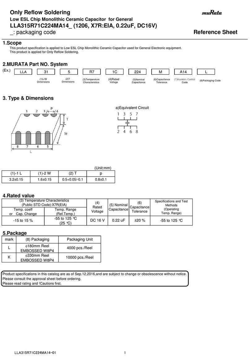
Murata
Murata LLA315R71C224MA14 Series Reference sheet
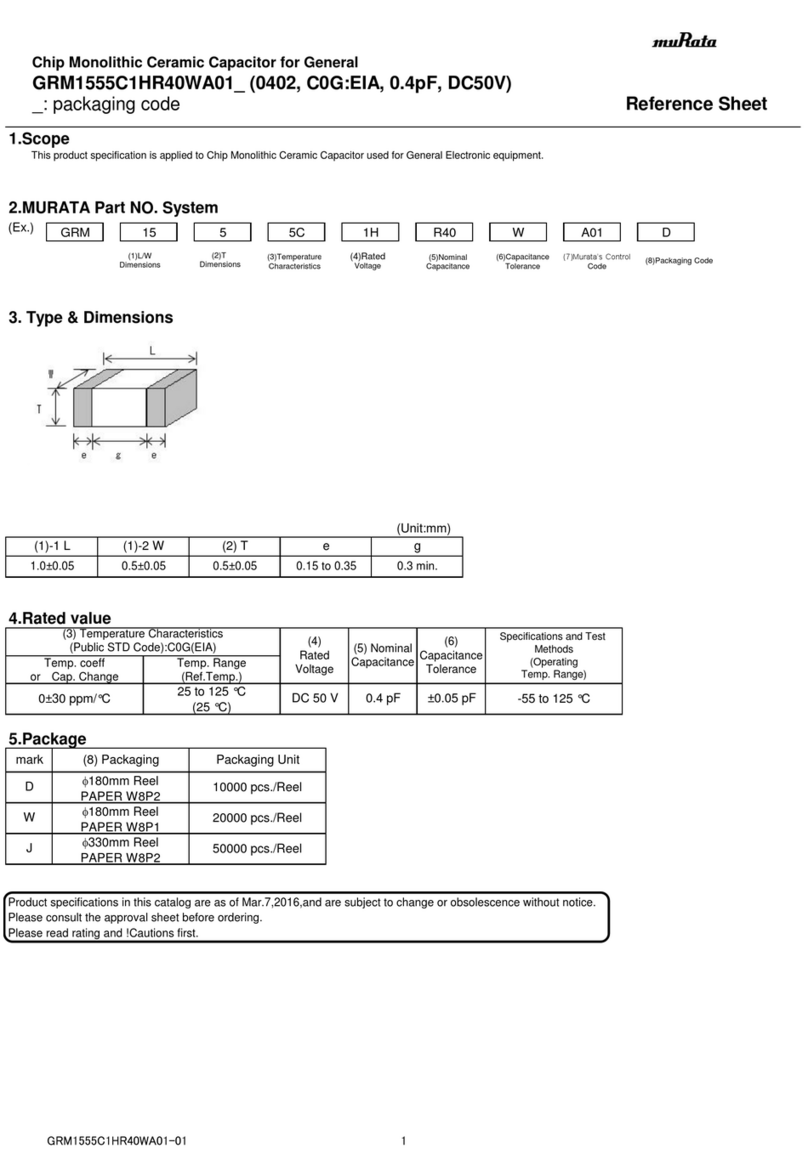
Murata
Murata GRM1555C1HR40WA01 Series Reference sheet
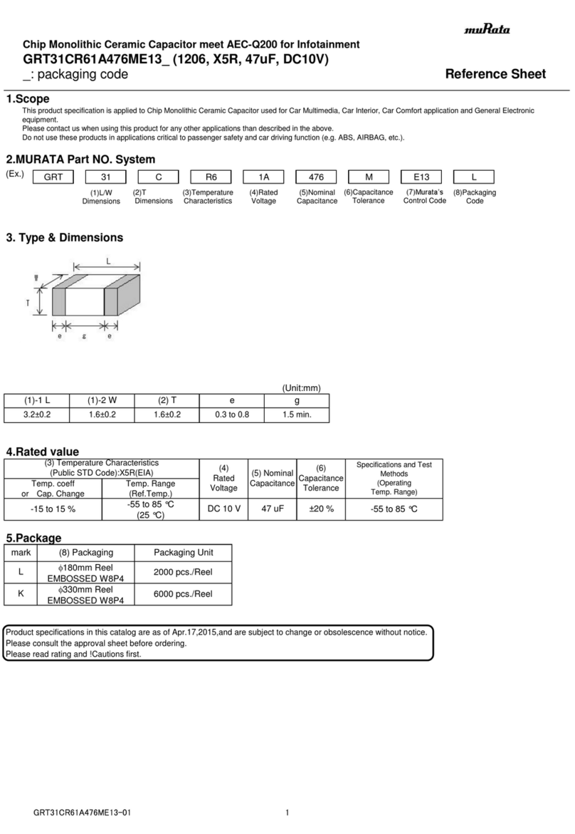
Murata
Murata GRT31CR61A476ME13 Series Reference sheet
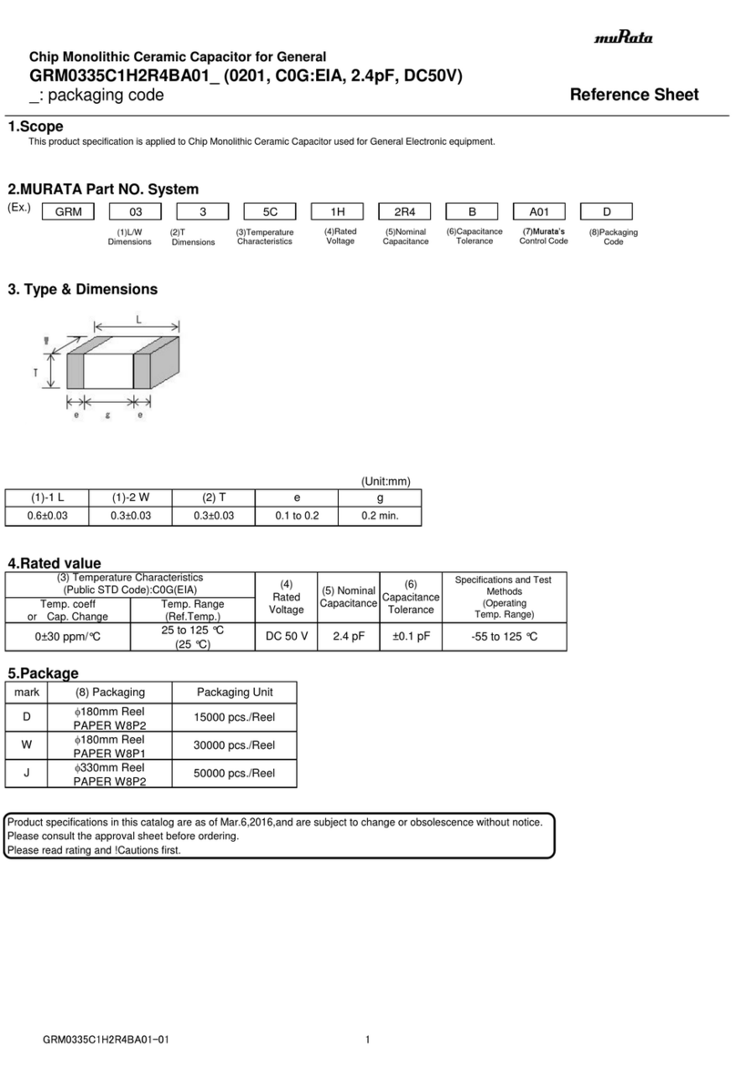
Murata
Murata GRM0335C1H2R4BA01 Series Reference sheet


