Volledige bedieningshandleiding 2
© Bredenoord 2017 2
Inhoud
1................................................................................................................................... 3
Volledige bedieningshandleiding
2................................................................................................................................... 4
Safety measures and symbols
................................................................................................................................... 42.1 Safety markings in the text
................................................................................................................................... 42.2 Safety instructions
................................................................................................................................... 42.3 Safety symbols on the ESaver
................................................................................................................................... 52.4 Switching safe
3................................................................................................................................... 6
Protections ................................................................................................................................... 63.1 Control circuit protections
................................................................................................................................... 63.2 Emergency stop
4................................................................................................................................... 7
Installation of the ESaver
5................................................................................................................................... 8
Connection of the ESaver
................................................................................................................................... 85.1 Electrical connections
................................................................................................................................... 85.2 Connecting power cables
6................................................................................................................................... 9
Operating instructions
................................................................................................................................... 96.1 Starting and stopping
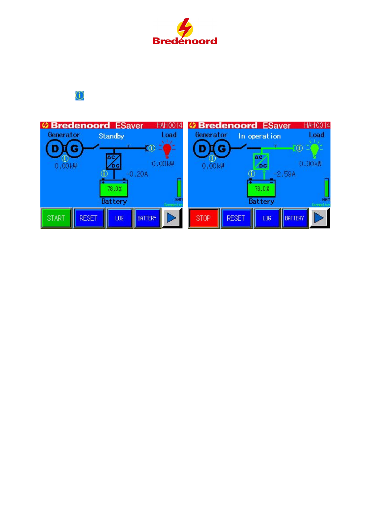
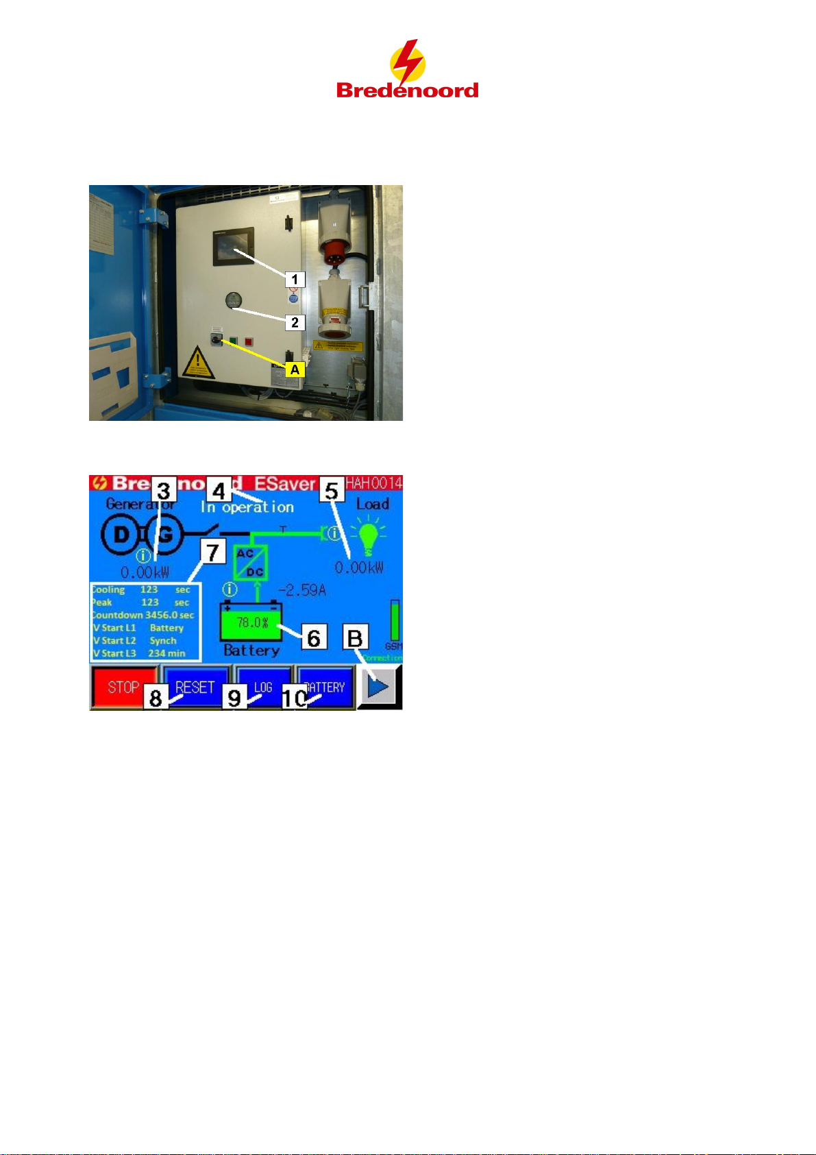
................................................................................................................................... 106.2 Main display
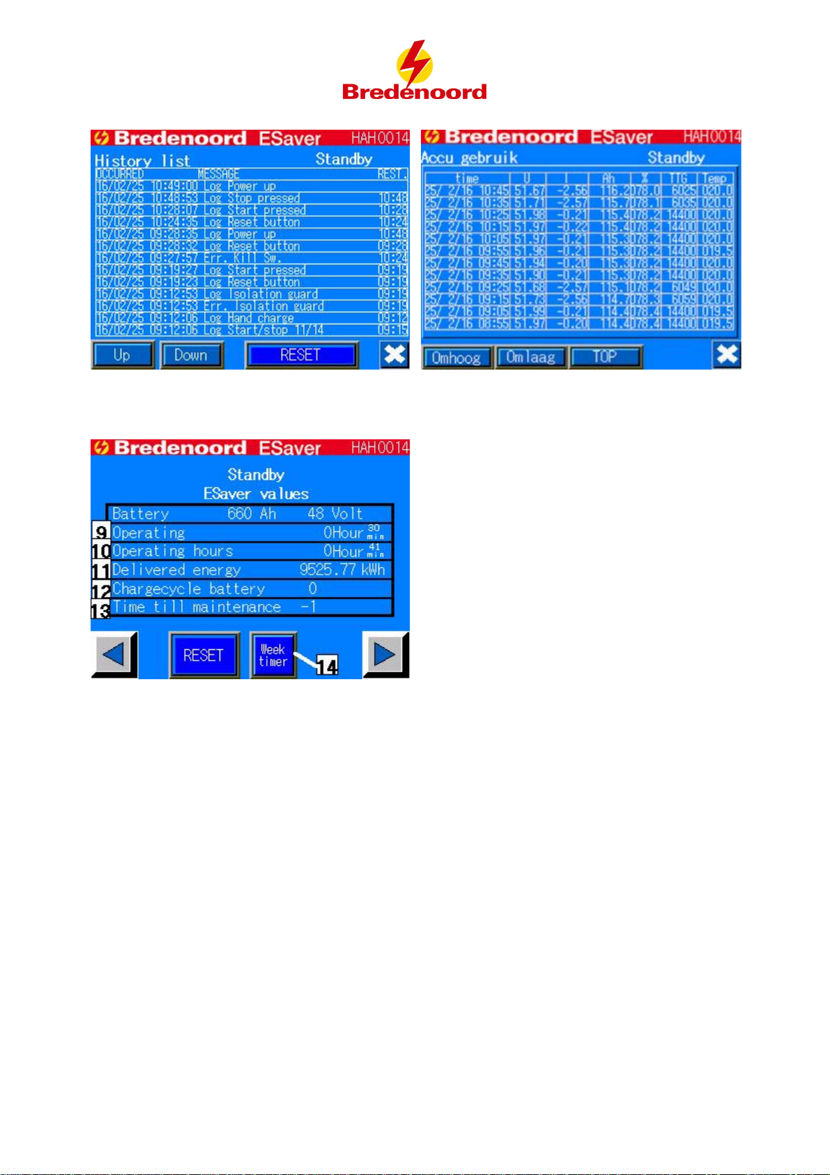
................................................................................................................................... 126.3 Reading data
................................................................................................................................... 146.4 Timer ................................................................................................................................... 156.5 Testing diesel genset
7................................................................................................................................... 17
Construction
8................................................................................................................................... 18
Service
9................................................................................................................................... 21
Trouble-shooting
10 ................................................................................................................................... 23
Moving the ESaver
11 ................................................................................................................................... 24
Maintenance
................................................................................................................................... 2411.1 Important points for maintenance
................................................................................................................................... 2511.2 Servicing
12 ................................................................................................................................... 26
Expiring of the warranty
13 ................................................................................................................................... 27
Technical data
................................................................................................................................... 0
EG-verklaring van overeenstemming IIA