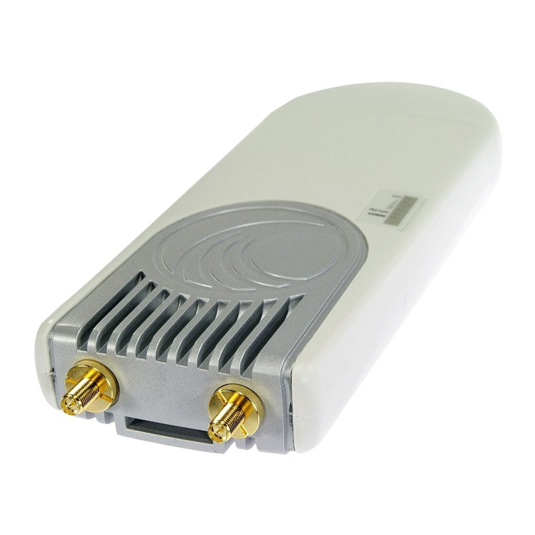
BreezeCOM SU-A-2.4 Series User manual

BreezeACCESS 2.4
Subscriber Units
SU-A-2.4 Series
SU-E-2.4 Series
Installation
Manual
Preliminary
Revision 3
November, 2000
Cat. No. 213123

Front Matter
SU-A/E Subscriber Units Installation Manual ii BreezeACCESS 2.4 Series
© 2000 by BreezeCOM Ltd. All rights reserved.
No part of this publication may be reproduced in any material form without the written permission of
the copyright owner.
Trade Names
BreezeACCESS, BreezeNET, BreezeLINK, BreezeVIEW, BreezeMANAGE and WIX are trade
names of BreezeCOM Ltd. Other brand and product names are registered trademarks or trademarks of
their respective companies.
Statement of Conditions
The information contained in this manual is subject to change without notice. BreezeCOM shall not be
liable for errors contained herein or for incidental or consequential damages in connection with the
furnishing, performance, or use of this manual or equipment supplied with it.
Warranty
In the following warranty text, “the Company” shall mean:
• BreezeCOM Ltd., for products located outside the USA.
• BreezeCOM Inc., for products located in the USA.
This BreezeACCESS product is warranted against defects in material and workmanship for a period of
one year from date of purchase. During this warranty period the Company will, at its option, either
repair or replace products that prove to be defective.
For warranty service or repair, the product must be returned to a service facility designated by the
Company. Authorization to return products must be obtained prior to shipment. The buyer shall pay all
shipping charges to the Company and the Company shall pay shipping charges to return the product to
the buyer.
The Company warrants that the firmware designed by it for use with the unit will execute its
programming instructions when properly installed on the unit. The Company does not warrant that the
operation of the unit or firmware will be uninterrupted or error-free.
Limitations of Warranty
The foregoing warranty shall not apply to defects resulting from improper or inadequate maintenance
by the buyer, buyer supplied interfacing, unauthorized modification or misuse, operation outside of the
environmental specifications for the product, or improper site preparation or maintenance. No other
warranty is expressed or implied. The Company specifically disclaims the implied warranties of
merchantability and fitness for any particular purpose.
BreezeCOM shall not be liable to any person for any special or indirect damages, including, but not

Front Matter
BreezeACCESS 2.4 Series iii SU-A/E Subscriber Units Installation Manual
limited to, loss of profits or revenues, loss of use or damage to any associated equipment, cost of
capital, cost of substitute products, facilities or services, downtime costs or claims resulting from any
cause whatsoever arising from or in any way connected with the manufacture, sale, handling, service,
repair, maintenance or use of the products. In no event shall the company’s liability exceed the
purchase price denoted on the invoice.
Electronic Emission Notice
This device complies with Part 15 of the FCC rules. Operation is subject to the following two
conditions:
1. This device may not cause harmful interference.
2. This device must accept any interference received, including interference that may cause
undesired operation.
FCC Radio Frequency Interference Statement
This equipment has been tested and found to comply with the limits for digital equipment,
pursuant to Part 15 of the FCC rules. These limits are designed to provide reasonable protection
against harmful interference when the equipment is operated in a residential environment
notwithstanding use in commercial, business and industrial environments. This equipment generates,
uses, and can radiate radio frequency energy and, if not installed and used in accordance with the
instruction manual, may cause harmful interference to radio communications.
Information to User
Any changes or modifications of equipment not expressly approved by the manufacturer could void the
user’s authority to operate the equipment.
Safety Considerations
For the following safety considerations, “Instrument” means the BreezeACCESS Subscriber Unit
components and its cables. To avoid shock, do not perform any servicing unless you are qualified.
RF Warning
To comply with FCC RF exposure requirements in section 1.1307, a minimum separation distance of
2m (79 inches) is required between the antenna and all persons.
Line Voltage
Before connecting this instrument to the power line, make sure that the voltage of the power source
matches the requirements of the instrument.

Front Matter
SU-A/E Subscriber Units Installation Manual iv BreezeACCESS 2.4 Series
Radio
The instrument transmits radio energy during normal operation. To avoid possible harmful exposure to
this energy, do not stand or work for extended periods of time in front of its antenna. The long-term
characteristics or the possible physiological effects of Radio Frequency Electromagnetic fields have
not been yet fully investigated.
Antenna Installation and Grounding
Be sure that the Outdoor unit, the antenna and the supporting structure are properly installed to
eliminate any physical hazard to either people or property. Verify that the antenna mast is grounded so
as to provide protection against voltage surges and static charges. Make sure that the installation of the
Outdoor unit, antenna and cables is performed in accordance with all relevant national and local
building and safety codes.

BreezeACCESS 2.4 Series v SU-A/E Subscriber Units Installation Manual
Table of Contents
1. INTRODUCTION .....................................................................................................................1
2. BASIC INSTALLATION..........................................................................................................4
2.1 Packing List...........................................................................................................................4
2.2 Other Items Required for Installation....................................................................................4
2.3 General Installation Scheme..................................................................................................5
2.4 Guidelines for Selection of Equipment Locations................................................................7
2.5 Installing the Outdoor Unit ...................................................................................................9
2.5.1 Pole Mounting the Outdoor Unit ...................................................................................9
2.5.2 Connecting the Antenna Cable (SU-RE) .....................................................................12
2.5.3 Connecting the Ground and IF Cables.........................................................................12
2.6 Installing the SU-NI Indoor Unit.........................................................................................13
3. CONFIGURING SYSTEM PARAMETERS........................................................................15
3.1 Getting Started with the Local Terminal.............................................................................15
3.2 Configuring Basic Parameters.............................................................................................17
3.3 Reset Unit............................................................................................................................18
4. ALIGNING THE ANTENNA.................................................................................................19
5. VERIFYING CORRECT OPERATION OF THE OUTDOOR UNIT..............................20
6. RSSI MEASUREMENT AND MAXIMUM DATA RATE CONFIGURATION .............21
6.1 Performing the RSSI Measurement.....................................................................................21
6.2 Configuring The Maximum Data Rate................................................................................22

Table of Contents
SU-A/E Subscriber Units Installation Manual vi BreezeACCESS 2.4 Series
7. VERIFYING CORRECT OPERATION ..............................................................................23
7.1 General ................................................................................................................................23
7.2 Verifying Data Connectivity...............................................................................................23
7.3 Verifying Telephone Connectivity (SU-A/E-DV series only)............................................24
8. SPECIFICATIONS .................................................................................................................25
8.1 Radio ...................................................................................................................................25
8.2 Data Communication...........................................................................................................26
8.3 Voice Communication (SU-A/E-DV series).......................................................................26
8.4 Outdoor Unit to Indoor Unit Communication.....................................................................26
8.5 Configuration and Management..........................................................................................26
8.6 Interfaces.............................................................................................................................27
8.7 Electrical, Mechanical and Environmental .........................................................................27
8.8 Standards Compliance, General..........................................................................................27
APPENDIX A. USING TELNET...............................................................................................28
APPENDIX B. BASIC PARAMETERS....................................................................................29

Table of Contents
BreezeACCESS 2.4 Series vii SU-A/E Subscriber Units Installation Manual
Table of Figures
Figure 2-1: SU-A General Installation Scheme.........................................................................5
Figure 2-2. SU-E General Installation Scheme .........................................................................6
Figure 2-3. Holes/Grooves/Screw holes....................................................................................9
Figure 2-4. SU-RA 2” Pole Mounting Installation Using the Special Brackets......................10
Figure 2-5. SU-RE 3” Pole Mounting Installation Using the Special Brackets......................11
Figure 2-6. SU-RA/RE Outdoor Unit Bottom Panel...............................................................12
Figure 2-7. SU-NI Rear Panel (unit with voice support).........................................................13
Figure 2-8. SU-NI Front Panel ................................................................................................14
Table of Tables
Table 1-1. BreezeACCESS SU-A-xD-2.4 Data Subscriber Units ............................................2
Table 1-2. BreezeACCESS SU-E-xD-2.4 Data Subscriber Units.............................................2
Table 1-3. BreezeACCESS SU-A-xD1V-2.4 Data Subscriber Units........................................3
Table 1-4. BreezeACCESS SU-E-xD1V-2.4 Data Subscriber Units........................................3
Table 3-1. Main Menu.............................................................................................................16
Table 5-1: SU-RA/RE Outdoor Unit LEDs.............................................................................20
Table 6-1: RSSI vs. Maximum Data Rate................................................................................22
Table 7-1: SU-NI LEDs............................................................................................................23


Introduction
BreezeACCESS 2.4 Series 1 SU-A/E Subscriber Units Installation Manual
1. INTRODUCTION
This manual describes installation guidelines for BreezeACCESS 2.4 SU-A and
SU-E series of Subscriber Units.
The BreezeACCESS IP Broadband Wireless Local Loop (WLL) system allows
access service providers to provide high-speed IP connectivity services to their
subscribers. To effectively support IP-based services BreezeACCESS systems
employ wireless packet data switching technology.
The BreezeACCESS 2.4 line of products uses Frequency Hopping Spread
Spectrum radios that operate in Time Division Duplex (TDD) mode in the
2.400GHz – 2.500GHz frequency range.
SU-A and SU-E series Subscriber Units are comprised of an indoor unit (SU-NI)
and an outdoor unit. In the SU-A product line, the outdoor unit (SU-RA)
contains the radio module and an integral flat antenna. In the SU-E series, the
outdoor unit (SU-RE) contains the radio module and an interface to an external
antenna (not included). The indoor unit provides the interface to the user’s
equipment and is powered from the mains via its SU-PS power supply unit. The
SU-NI also contains an IF (Intermediate Frequency) module and is connected to
the outdoor unit via a 50-ohm coaxial IF cable. The IF cable serves for
transmission of the 440MHz IF signal between the indoor and the outdoor units.
It also serves for transferring power (12VDC), management and control signals
from the indoor unit to the outdoor unit.

Introduction
SU-A/E Subscriber Units Installation Manual 2 BreezeACCESS 2.4 Series
Table 1-1 lists the products included in the BreezeACCESS SU-A-xD-2.4 Data
Subscriber Units.
Table 1-2 lists the products included in the BreezeACCESS SU-E-xD-2.4 Data
Subscriber Units.
Table 1-3 lists the products included in the BreezeACCESS SU-A-xD1V-2.4
Data and Voice Subscriber Units.
Table 1-4 lists the products included in the BreezeACCESS SU-E-xD1V-2.4
Data and Voice Subscriber Units.
Table 1-1. BreezeACCESS SU-A-xD-2.4 Data Subscriber Units
Product CPE support General Description
SU-A-1D-HP-2.4
SU-A-1D-LP-2.4 Supports a single
Ethernet device. Indoor unit, power supply and an
outdoor radio unit with an
integral flat antenna.
SU-A-8D-HP-2.4
SU-A-8D-LP-2.4 Supports up to eight
Ethernet
workstations/PCs
Output power at antenna port:
26 dBm (SU-A-xD-HP-2.4) or
2 dBm (SU-A-xD-LP-2.4)
SU-A-BD-HP-2.4
SU-A-BD-LP-2.4 Supports a LAN
(bridge functionality)
Table 1-2. BreezeACCESS SU-E-xD-2.4 Data Subscriber Units
Product CPE support General Description
SU-E-1D-HP-2.4
SU-E-1D-LP-2.4 Supports a single
Ethernet device Indoor unit, power supply and an
outdoor radio unit with an RF
connector to an external antenna.
SU-E-8D-HP-2.4
SU-E-8D-LP-2.4 Supports up to eight
Ethernet
workstations/PCs
Output power at antenna port:
26 dBm (SU-E-xD-HP-2.4) or
2 dBm (SU-E-xD-LP-2.4)
SU-E-BD-HP-2.4
SU-E-BD-LP-2.4 Supports a LAN
(bridge functionality)

Introduction
BreezeACCESS 2.4 Series 3 SU-A/E Subscriber Units Installation Manual
Table 1-3. BreezeACCESS SU-A-xD1V-2.4 Data and Voice Subscriber Units
Product CPE support General Description
SU-A-1D1V-HP-2.4
SU-A-1D1V-LP-2.4 Supports a single
Ethernet device and
a regular telephone
interface.
Indoor unit, power supply and an
outdoor radio unit with an
integral flat antenna.
Output power at antenna port:
SU-A-8D1V-HP-2.4
SU-A-8D1V-LP-2.4 Supports up to
eight Ethernet
workstations/PCs
and a regular
telephone interface.
26 dBm (SU-A-xD1V-HP-2.4) or
2 dBm (SU-A-xD1V-LP-2.4)
SU-A-BD1V-HP-2.4
SU-A-BD1V-LP-2.4 Supports a LAN
(bridge
functionality) and a
regular telephone
interface.
Table 1-4. BreezeACCESS SU-E-xD1V-2.4 Data and Voice Subscriber Units
Product CPE support General Description
SU-E-1D1V-HP-2.4
SU-E-1D1V-LP-2.4 Supports a single
Ethernet device and
a regular telephone
interface.
Indoor unit, power supply and an
outdoor radio unit with an RF
connector to an external antenna.
Output power at antenna port:
SU-E-8D1V-HP-2.4
SU-E-8D1V-LP-2.4 Supports up to
eight Ethernet and
a regular telephone
interface.
26dBm (SU-E-xD1V-HP-2.4) or
2dBm (SU-E-xD1V- LP-2.4)
SU-E-BD1V-HP-2.4
SU-E-BD1V-LP-2.4 Supports a LAN
(bridge
functionality) and a
regular telephone
interface.
Note: The information contained in this manual is applicable to BreezeACCESS 2.4
units with software release 2.5 and up.

Basic Installation
SU-A/E Subscriber Units Installation Manual 4 BreezeACCESS 2.4 Series
2. BASIC INSTALLATION
2.1 Packing List
• SU-NI Indoor unit
• Outdoor unit
⇒ SU-RA with integral antenna
or
⇒ SU-RE with a connector to an external antenna (not included)
• SU-PS power supply with a mains power cord
• Pole mounting kit for the Outdoor unit (with two brackets, four sets of
screws, nuts and washers)
• Wall mounting kit for the SU-NI unit
• Telephone cord (with units that support voice)
2.2 Other Items Required for Installation
• IF cable* (available from BreezeCOM in different lengths)
• Grounding cable with an appropriate termination
• Antenna* and RF cable* (SU-E only)
• Ethernet cable (straight)
• A portable PC with terminal emulation software
• Monitor cable* (supplied with the base station equipment)
• Installation tools and materials.
Items marked with an asterisk (*) are available as options from BreezeCOM.

Basic Installation
BreezeACCESS 2.4 Series 5 SU-A/E Subscriber Units Installation Manual
2.3 General Installation Scheme
Figure 2-1 depicts the general installation scheme for BreezeACCESS SU-A-2.4
Subscriber Units; Figure 2-2 depicts the general installation scheme for
BreezeACCESS SU-E-2.4 Subscriber Units.
INDOOR
UNIT
IF CABLE TO
OUTDOOR UNIT
TO MAINS
TO DATA
EQUIPMENT
GROUNDING
CABLE
OUTDOOR
UNIT
POWER
SUPPLY
INDOOR
UNIT
IF CABLE TO
OUTDOOR UNIT
TO MAINS
GROUNDING
CABLE
OUTDOOR
UNIT
TO TELEPHONE EQUIPMENT
(SU-A/E-DV SERIES ONLY)
POWER
SUPPLY
Figure 2-1: SU-A General Installation Scheme

Basic Installation
SU-A/E Subscriber Units Installation Manual 6 BreezeACCESS 2.4 Series
INDOOR
UNIT
IF CABLE TO
OUTDOOR UNIT
TO MAINS
TO DATA
EQUIPMENT
GROUNDING
CABLE
OUTDOOR
UNIT
POWER
SUPPLY
TO TELEPHONE EQUIPMENT
(SU-A/E-DV SERIES ONLY)
TO ANTENNA
Figure 2-2. SU-E General Installation Scheme

Basic Installation
BreezeACCESS 2.4 Series 7 SU-A/E Subscriber Units Installation Manual
2.4 Guidelines for Selection of Equipment Locations
Select appropriate locations for the Outdoor unit and for the Indoor unit using
the following guidelines.
SU-RA
• The SU-RA Outdoor unit should be mounted on a pole and should be
installed on a rooftop or a side-wall where a direct line of sight with the Base
Station antenna can be established. The higher the unit, the better the
achievable link quality.
• The antenna (integrated on the front side of the SU-RA Outdoor unit) should
be directed towards the Base Station. The unit should be installed in a way
that allows optimal alignment towards the Base Station. The location should
also be selected to allow easy access to the unit for installation and testing.
SU-RE
• The SU-RE outdoor unit should be installed as near as possible to its antenna.
• The antenna should be mounted on a pole and should be installed on a roof
top or side wall where a direct line of site with the Base Station can be
established. The higher the antenna, the better the achievable link quality.
• The antenna should be directed towards the Base Station. The antenna
should be installed in a way that allows optimum alignment towards the Base
Station. The location of the antenna should allow easy access for installation
and alignment.
SU-RA/RE
• The SU-RA/RE is connected to the SU-NI by means of an IF cable carrying
signaling, control signals and power. The IF frequency is 440 MHz. The
maximum allowed attenuation of the IF cable connecting the Outdoor unit to
the Indoor unit is 15dB and the maximum allowed DC resistance (the sum of
the DC resistance of the inner and outer conductors) is 1.5 ohm. This allows
for cable length of up to 30m when using the standard RG 58 cable.
If longer cables are required, a cable with lower attenuation and/or DC
resistance should be used. Table 2-1 provides details regarding some popular
cables such as the RG 58 and RG 213. If the spectral environment is polluted
with noise in the 440 MHz band, it is recommended to use a higher quality

Basic Installation
SU-A/E Subscriber Units Installation Manual 8 BreezeACCESS 2.4 Series
double-shielded cable such as the LMR 240 or LMR 400 (manufactured by
Times Communications).
Table 2-1: IF Cables
Cable Type RG 58 RG 213 LMR 240 LMR 400
Maximum cable
Length (m) 30 100 65 150
• The Indoor unit should be installed in as close as possible to the building’s
entry point of the IF cable. The location of the Indoor unit should also take
into account the need to connect it to a power mains outlet and to the CPE.
Notice: Outdoor units and antennas should be installed ONLY by experienced
installation professionals who are familiar with local building and safety
codes and, wherever applicable, are licensed by the appropriate government
regulatory authorities.
The system complies with the EN61000-4-5, level 3 (2kV) standard and is protected
against secondary lightning strikes when its outdoor unit is properly
grounded according to the applicable country-specific industry standards
for protection of structures against lightning. The use of any antenna other than
those certified with this product is forbidden in accordance to FCC rules 15.204.
Failure to do so may void the BreezeACCESS product warranty and may
expose the end user or the service provider to legal and financial liabilities.
BreezeCOM and its resellers or distributors are not liable for injury,
damage or violation of regulations associated with the installation of
outdoor units or antennas. Reffer to Appendix C for approved antennas.

Basic Installation
BreezeACCESS 2.4 Series 9 SU-A/E Subscriber Units Installation Manual
2.5 Installing the Outdoor Unit
2.5.1 Pole Mounting the Outdoor Unit
The Outdoor unit can be secured to the pole using one of the following options:
• Special brackets and open-ended screws (supplied with each unit). There
are two pairs of screw holes on the back of the unit, allowing use of the
special brackets with various pole widths.
• U-bolts – size A (inner installation holes, up to 2” pole).
• U-bolt – size B (outside installation holes, up to 3” pole).
• Metal bands (9/16” wide, minimum 12” long)
Figure 2-3 shows the locations of the u-bolt holes, band grooves and screw holes
on the rear side of the Outdoor unit.
Figure 2-4 illustrates the method of installing an SU-RA Outdoor unit on a pole,
using the brackets and open-ended screws.
Figure 2-5 illustrates the method of installing an SU-RE Outdoor unit on a pole,
using the brackets and open-ended screws.
Note: Make sure to install the unit with the bottom panel (the panel with the IF
connector) facing downward.
Bracket Screw Holes
Grooves for Insertion of 9/16” Metal Band
Size B U-Bolt Holes (3” Pole)
Size A U-Bolt
Holes (2” Pole)
Figure 2-3. Holes/Grooves/Screw holes

Basic Installation
SU-A/E Subscriber Units Installation Manual 10 BreezeACCESS 2.4 Series
Figure 2-4. SU-RA 2” Pole Mounting Installation Using the Special Brackets
Note: When inserting the open-ended screws, make sure to insert them with the
grooves pointing outwards; these grooves are intended to allow fastening of
the screws with a screwdriver.

Basic Installation
BreezeACCESS 2.4 Series 11 SU-A/E Subscriber Units Installation Manual
Figure 2-5. SU-RE 3” Pole Mounting Installation Using the Special
Brackets
Note: When inserting the open-ended screws, make sure to insert them with the
grooves pointing outwards; these grooves are intended to allow fastening of
the screws with a screwdriver.

Basic Installation
SU-A/E Subscriber Units Installation Manual 12 BreezeACCESS 2.4 Series
2.5.2 Connecting the Antenna Cable (SU-RE)
Connect an RF cable between the ANT connector (located on the top panel of
the SU-RE unit) and the antenna.
2.5.3 Connecting the Ground and IF Cables
The Ground terminal (marked
and the IF cable connector (marked IF) are
located on the bottom panel of the SU-RA/RE Outdoor unit, shown in
Figure 2-6.
ETH
ALARM RSSI
IF
WLNK
Figure 2-6. SU-RA/RE Outdoor Unit Bottom Panel
1. Connect one end of the ground cable to the Ground terminal and connect the
other end to a good ground connection.
2. Connect the coaxial cable to the IF connector. Verify that the length of the
IF cable is sufficient and that it can easily reach the Indoor unit.
Note: Make sure to switch OFF the power of the SU-NI unit prior to
connecting/disconnecting the IF cable.
Ground
Screw
This manual suits for next models
26
Table of contents
Other BreezeCOM Wireless Access Point manuals
Popular Wireless Access Point manuals by other brands
Linksys
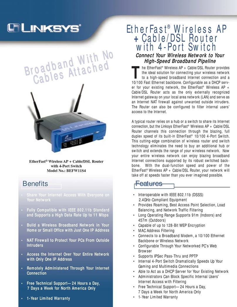
Linksys EtherFast Instant Broadband BEFW11S4 Brochure & specs
ZyXEL Communications
ZyXEL Communications NWA Seres user guide
FRÄNKISCHE
FRÄNKISCHE 100 DATALIGHT operating instructions
Ruckus Wireless
Ruckus Wireless R720 Quick setup guide
Atlantis Land
Atlantis Land A02-AP1-W54 manual
Carel
Carel WS01RC1M20 instructions
