1 Overview
1 Licensing notes
Each device includes various instruc-
tions/information for the following areas:
ninstallation (with technical data)
nlicense
noperation
Please categorically note
the instructions for all
three areas – in particular
the safety instructions pro-
vided with the installation
instructions enclosed with
the devices.
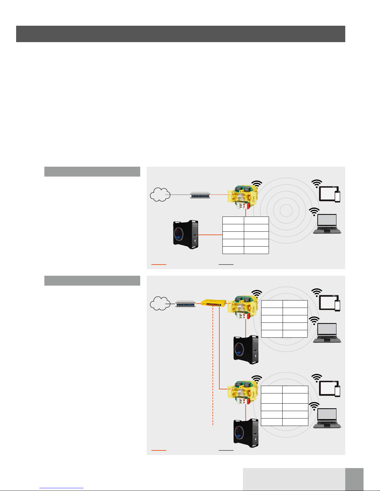
Intended use
The wireless access point (WLAN AP)
has different operating modes and func-
tions. It can, among other things, be
used as access point for devices com-
municating wireless or as a repeater to
increase the range of the wireless net-
work.
It can also be connected to devices
which have no own WLAN adapter.
Do not use the device for any other pur-
pose. Only operate it in interior spaces.
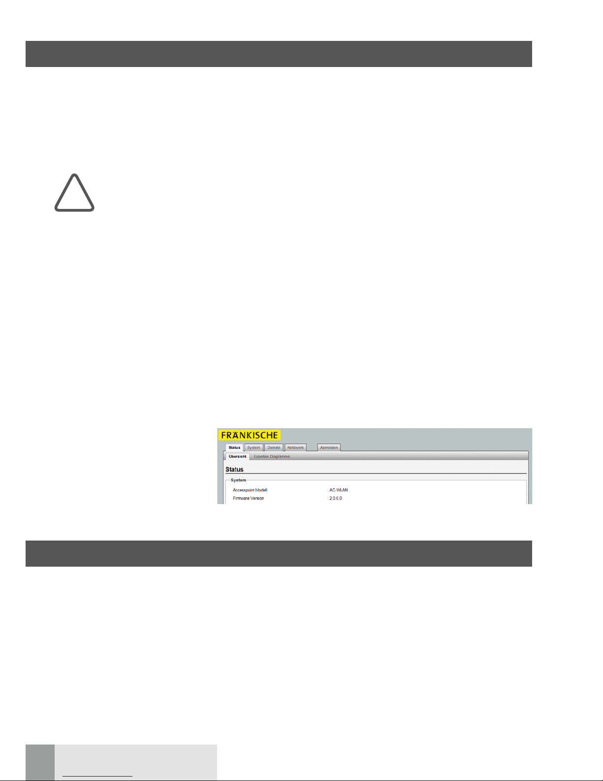
These operating instructions apply only
to devices equipped with firmware ver-
sion 2.x to 4.x (see following figure).
General information
The WLAN AP offers an excellent alter-
native to comply with the requirements
of modern network infrastructures
according to DIN 18015-2 and RAL-RG
678 without having to refrain from the
flexible use of modern, mobile technolo-
gies such as tablet PCs or laptops and
without restricting wireless data rates.
In addition, the WLAN AP works like a
normal data socket with a RJ45 outlet
for a conventional data terminal (data
rate of 100 Mbps). Power is supplied
directly via 230 V on the rear side of the
device.
The WLAN AP is connected to the inter-
nal data network via polymer optical
fibres (POF).
The WLAN range can be adapted to the
room conditions and it can be limited to
the room. This creates powerful room
radio cells which ensure maximum
radio bandwidth within the room while
at the same time operating with low
power consumption and low radiation.
Due to its low energy consumption and
thus low radio emissions, demarcation
problems among individual access
points, over-coupling of WLAN sections
and compromised data rates are largely
avoided.
The WLAN AP can also be controlled
directly via UDP and features extensive
time switching and additional protocol
functions.
It is the first wireless access point world-
wide to fit in a commercial installation
box and also matches all design pro-
grammes of renowned switch manufac-
turers.
Parts of the firmware are subject to the
GNU General Public License.
License information
This product includes software by third
parties under the terms of the GNU
General Public License.
You can use, change or distribute this
free software under the terms of the
GNU General Public License.
Availability of the source code
Upon request, we will send you the
complete source code of the software
licensed under GNU General Public
License – including all scripts to control
the compilation and installation of the
drivers. The complete license details can
be found in a separate document.
System requirements
nLAN connection via POF cable
nfirmware 2.x and higher
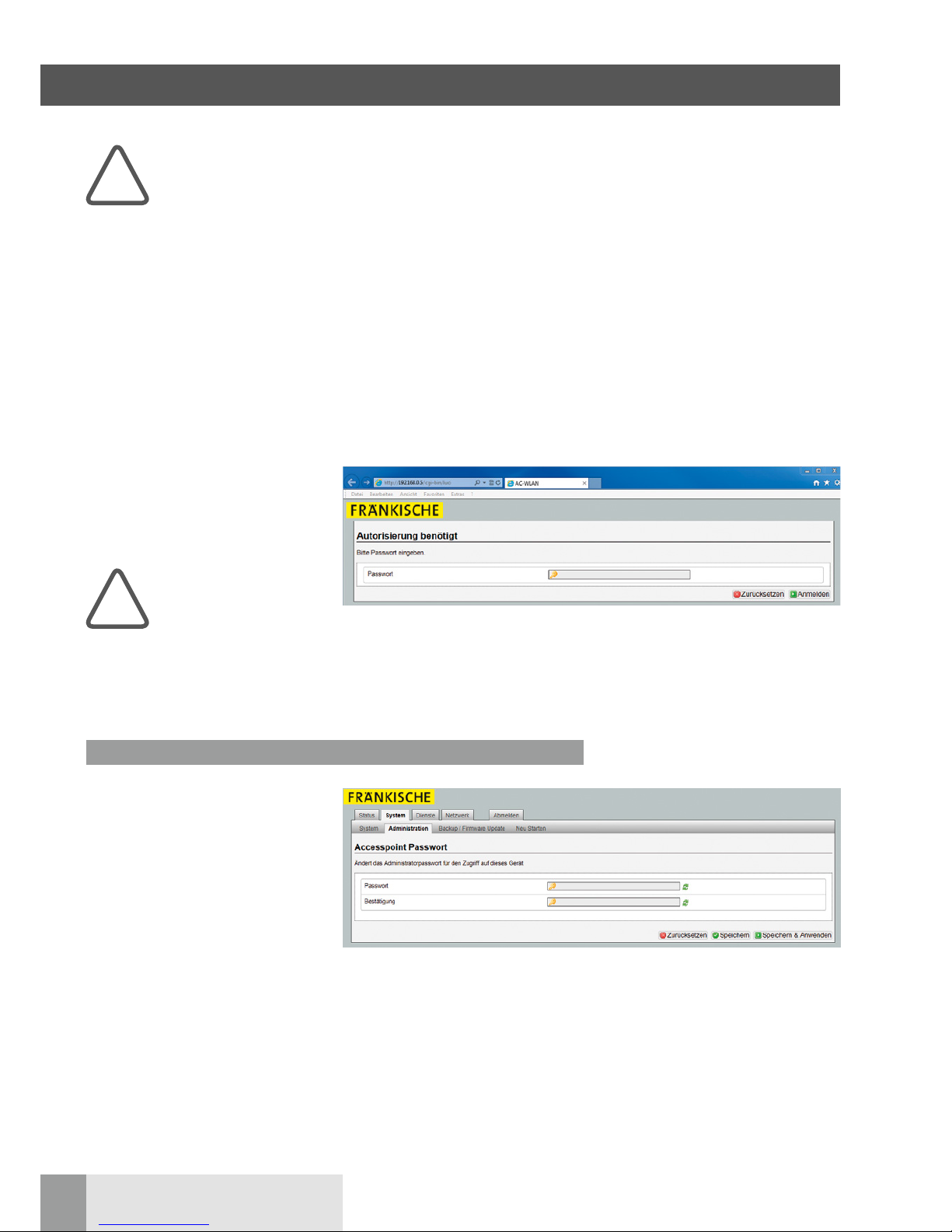
nPC/laptop/tablet with internet
browser
!


 installation guide")
