breezEV EVC-L2-R40 User manual

12 July 2023 Page | 1
breezEV Level 2 Charging Station Install Guide – R48
BreezEV offers best-in-class hardware and technical support. If you have any questions during installation, please do not
hesitate to contact us.

12 July 2023 Page | 2
Table of Contents
Safety and Compliance ..................................................................................................................................................................... 3
Before Installation, Please Read
Summary of Shipping Boxes ....................................................................................................................................................... 4-6
Specifications ................................................................................................................................................................................. 6
Dimensions ................................................................................................................................................................................. 7-9
Wiring Diagram & Requirements ................................................................................................................................................. 10
Tools Required ............................................................................................................................................................................. 11
Wall-Mount Installation
Mechanical Installation ........................................................................................................................................................... 11-12
Electrical Connections ............................................................................................................................................................. 12-16
Non-Cable Management Pedestal Installation
Installation .............................................................................................................................................................................. 17-22
Electrical Connections ............................................................................................................................................................. 12-16
Cable Management Pedestal Installation
Installation .............................................................................................................................................................................. 17-24
Electrical Connections ............................................................................................................................................................. 12-16
Status Descriptions on Charger
Normal ........................................................................................................................................................................................ 25
Abnormal/Troubleshooting ......................................................................................................................................................... 26

12 July 2023 Page | 3
Safety and Compliance
SAVE THESE SAFETY INSTRUCTIONS
This manual contains important instructions that must be followed during installation of a breezEV Charging Station.
WARNINGS
This manual contains important instructions for breezEV EVC-L2 series that shall be followed during installation, operation, and maintenance of the unit.
1. Read all the instructions before using this product.
2. This device should be supervised when used around children.
3. Do not put fingers into the electric vehicle connector.
4. Do not use this product if the flexible power cord or EV cable is frayed, has broken insulation, or any other signs of damage.
5. Do not use this product if the enclosure or the EV connector is broken, cracked, open, or shows any other indication of damage.
6. To reduce the risk of fire, connect only to a circuit provided branch circuit over-current protection in accordance with the CSA C22.1–15 Canadian Electrical Code,
Part 1 (Canada) or NOM-001-SEDE Electrical installations (utility) (Mexico) or ANSI / NFPA 70 National Electrical Code (USA).
7. To avoid a risk of fire or electric shock, do not use this device with an extension cord.
8. THE SUITABILITY OF THE USE OF FLEXIBLE CORD IN ACCORDANCE WITH CE CODE, PART I, RULE 4-012, IS TO BE DETERMINED BY THE LOCAL INSPECTION AUTHORITY
HAVING JURISDICTION.
9. Risk of electric shock. Do not remove cover or attempt to open the enclosure. No user serviceable parts inside. Refer servicing to qualified service personnel.
AVERTISSEMENT – Ce manuel contient des instructions importantes pour les modèles: série EVC-L2 qui doit être suivie pendant l'installation, le fonctionnement et la
maintenance de l'unité.
1. Lisez toutes les instructions avant d'utiliser ce produit.
2. Cet appareil doit être surveillé lorsqu'il est utilisé à proximité d'enfants.
3. Ne pas mettre les doigts dans le connecteur du véhicule électrique.
4. N'utilisez pas ce produit si le cordon d'alimentation flexible ou le câble EV est effiloché, a une isolation cassée, ou tout autre signe de dommage.
5. N'utilisez pas ce produit si le boîtier ou le connecteur EV est cassé, fissuré, ouvert ou montre toute autre indication de dommage.
6. Pour réduire les risques d'incendie, ne connecter qu'à un circuit protection contre les surintensités des circuits de derivation conformément à la norme canadienne
CSA C22.1-15 Code électrique, partie 1 (Canada) ou NOM-001-SEDE Installations électriques (service public) (Mexique) ou ANSI / NFPA 70 National Electrical Code
(États-Unis).
FCC Compliance Statement
This device complies with part 15 of the FCC Rules.
Operation is subject to the following two conditions:
1. This device may not cause harmful interference,
2. This device must accept any interference received, including interference that may cause undesired operation.
Caution: Changes or modifications to this unit not expressly approved by the party responsible for compliance could void the user's authority to operate the equipment.
Note: This equipment has been tested and found to comply with the limits for a Class A digital device, pursuant to part 15 of the FCC Rules. These limits are designed to
provide reasonable protection against harmful interference when the equipment is operated in a commercial environment. This equipment generates, uses, and can radiate
radio frequency energy and, if not installed and used in accordance with the instruction manual, may cause harmful interference to radio communications. Operation of this
equipment in a residential area is likely to cause harmful interference in which case the user will be required to correct the interference at his own expense.
WIFI module: FCC ID:2AC7Z-ESPWROOM32D
LTE module: FCC ID: XMR202008EC25AFXD
To satisfy FCC RF exposure requirements, a separation distance of 20cm or more should be maintained between the antenna of this device and persons during device
operation. To ensure compliance, operations at closer than this distance is not recommended.
DESIGN STANDARDS FOLLOWED
The following UL testing & certification protocols have been followed:
UL 2594: Electric Vehicle Supply Equipment
UL 2231-1: Personnel Protection Systems for Electric Vehicle (EV) Supply Circuits: General Requirements
UL 2231-2: Personnel Protection Systems for Electric Vehicle (EV) Supply Circuits: Requirements for Protection Devices for Use in Charging Systems
UL 2251: Plugs, Receptacles and Couplers for Electric Vehicles
UL 62: Flexible Cords and Cables
UL 991: Tests for Safety-Related Controls Employing Solid-State Devices
UL 1998: Software in Programmable Components
NFPA 70 Article 625: National Electrical Code, Electric Vehicle Charging System
UL 840 (Clearance and Creepage)
WARRANTY STATEMENTS
Please see breezEV Standard Limited Warranty & Ultimate-Guard Program Details, both located on our website.

12 July 2023 Page | 4
Summary of Shipping Boxes
CHARGER
Part Name Label/Part # on Box Box Contents Example Drawing/Image of Box Contents
Charger Head EVC-L2-48A-L1-1-NC-N-1 1. Charger head (non-screen unit) (QTY 1)
2. Charger User Manual (QTY 1)
3. Wall-Mount Bracket (QTY 1)
4. M5 Wall-Mount Bracket Screws (QTY 2)
5. M6 Hexagonal Wall-Mount Bracket
Expansion Screws (QTY 4)
6. RFID Cards (QTY 5)
Hardware Kit EVC-L2-ACC-HARDWARE
KIT
1. Liquid tight for incoming power wires (QTY
2)
2. Incoming power wires (QTY 3)
3. Liquid tight fittings for incoming power
cable & charging cable (QTY 2)
4. J1772 Holster (QTY 1)
5. Mounting screws for J1772 Holster (QTY 4)
CHARGING CABLE SET
Part Name Label/Part # on Box Box Contents Example Drawing/Image of Box Contents
Charging Cable
Set
EVC-L2-CBL-40A-L1-1-XX
Or
EVC-L2-CBL-48A-L1-1-XX
1. Cable with J1772 plug on one end and crimped
terminals on the other
WET CONCRETE PEDESTAL ANCHOR KIT (only needed for wet concrete pours)
Part Name Label/Part # on Box Box Contents Example Drawing/Image of Box Contents
Wet Concrete
Pedestal Anchor
Kit
EVC-L2-ACC-ANCHOR KIT
WET
1. Wet concrete J-bolts (QTY 4)
2. Paper template (QTY 1)
12 July 2023 Page | 5
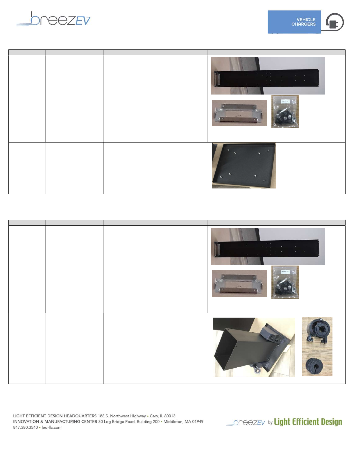
NON-CABLE MANAGEMENT PEDESTAL (EVC-L2-ACC-BB)
Part Name Label/Part # on Box Box Contents Example Drawing/Image of Box Contents
Pedestal Lower
Section
EVC-L2-ACC-LPK 1. Lower pedestal main section (QTY 1)
2. Lower pedestal cover (QTY 1)
3. UL Listed Junction Box w/ integral terminal
block (QTY 1)
4. Bag of hardware (QTY 1)
5. Pedestal Base Plate (QTY 1)
6. Existing concrete mounting bolts/washers
(QTY 4)
Non-cable
Management
Top Cover
EVC-L2-ACC-LPC 1. Non-cable management top cover (QTY 1)
2. Bag of hardware (QTY 1)
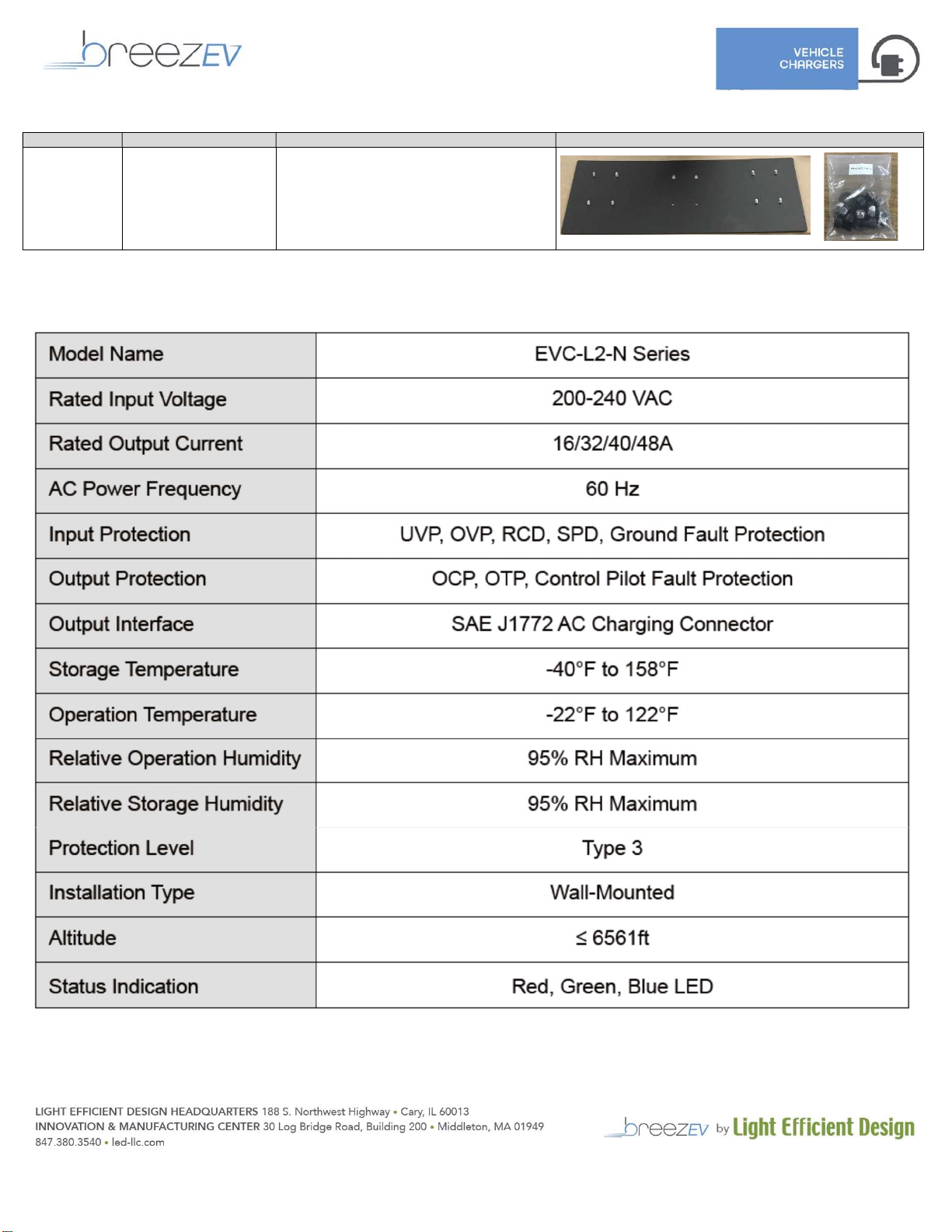
CABLE MANAGEMENT PEDESTAL (EVC-L2-ACC-CM1)
Part Name Label/Part # on Box Box Contents Example Drawing/Image of Box Contents
Pedestal Lower
Section
EVC-L2-ACC-LPK 1. Lower pedestal main section (QTY 1)
2. Lower pedestal cover (QTY 1)
3. UL Listed Junction Box w/ integral terminal
block (QTY 1)
4. Bag of hardware (QTY 1)
5. Pedestal Base Plate (QTY 1)
6. Existing concrete mounting bolts/washers
(QTY 4)
Cable
Management
Top Cover
EVC-L2-ACC-CM 1. Cable management top cover (QTY 1)
2. Bag of hardware (QTY 1)
3. Cable tensioners (QTY 2)
4. Cable tensioner – cable clamp glands (to
change from 40A gland to 48A gland) (QTY 2)
12 July 2023 Page | 6
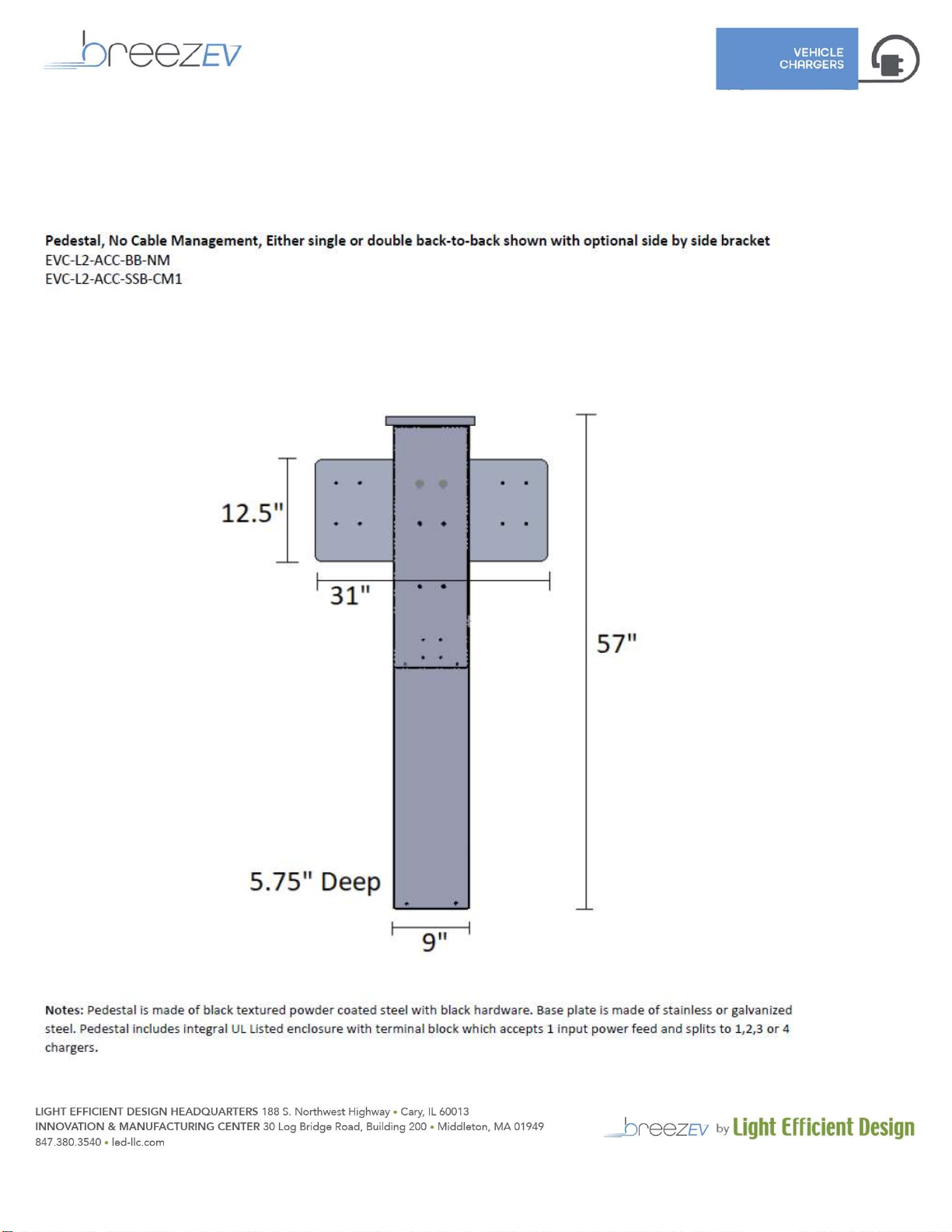
SIDE BY SIDE PEDESTAL MOUNTING BRACKET
Part Name Label/Part # on Box Box Contents Example Drawing/Image of Box Contents
Bracket for
either pedestal
style to allow for
side by side
install of
chargers
EVC-L2-ACC-SSB 1. Side by side bracket (QTY 1)
2. Bag of hardware (QTY 1)
SPECIFICATIONS

12 July 2023 Page | 7
DIMENSIONS
CHARGER
12 July 2023 Page | 8
NON-CABLE MANGAGEMENT PEDESTAL

12 July 2023 Page | 9
CABLE MANGAGEMENT PEDESTAL
12 July 2023 Page | 10
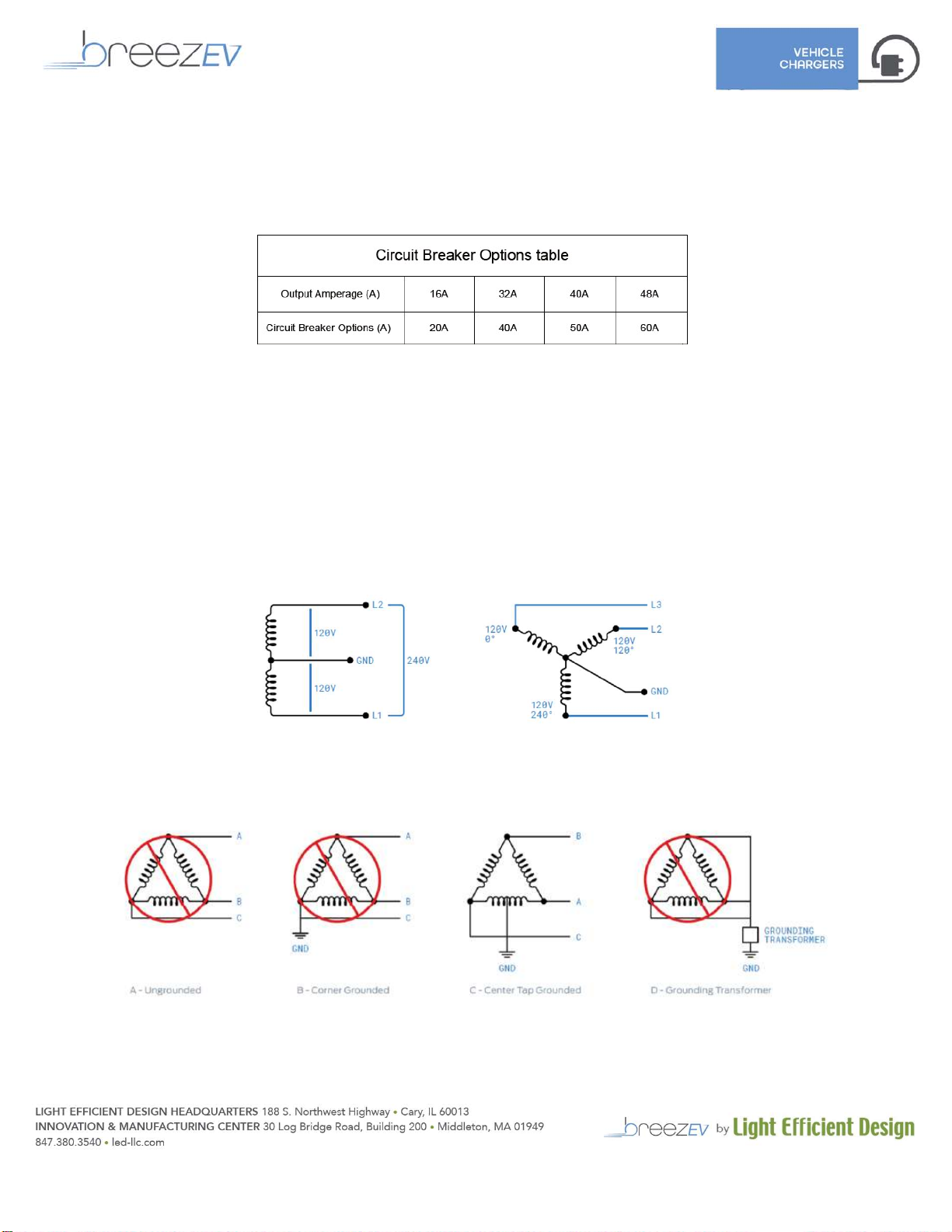
WIRING DIAGRAM & REQUIREMENTS
Key Requirements
1. EV charging stations shall be on a dedicated electrical circuit.
2. Each station shall be protected with a 2-pole common trip circuit breaker (non-GFCI type) as indicated by the below
table:
3. If a pedestal with 2 chargers is installed with a single feed, the circuit breaker must be rated at 2X the options listed in
the table above.
4. Each station is designed to draw a maximum of 48 amps.
5. Each station can operate on either a 240V or 208V circuit.
6. Each station requires three electrical supply wires (two hot, one ground, no neutral).
Wiring Diagram
Connect breezEV stations to any one of the power sources as shown:
1. 208 VAC three phase, Delta system, Center tap grounded (use only two phases)
2. 208 VAC three phase, Wye system (use only two phases)
3. 240 VAC single phase
In a delta system, connect the breezEV station only to a center-tapped grounded transformer only as
shown below. Connect the station to the side where ground is bonded (in figure C line A and C). This allows
voltages to remain constant regardless of other loads that may be using the lines. Please do not connect to
other type of power sources shown below.

12 July 2023 Page | 11
TOOLS REQUIRED
The following tools are required:
1. Wire strippers
2. Phillips screwdriver/Torq screwdrivers/Allen head screwdrivers
3. Adjustable pliers and/or wrenches
4. Multimeter
5. Tape measurer and level
6. Pencil
7. Drill
WALL-MOUNT INSTALLATION
Mechanical Installation
12 July 2023 Page | 12
Electrical Connections
GROUNDING INSTRUCTIONS
This product must be grounded. If it should malfunction or break down, grounding provides a path of least resistance for
electric current to reduce the risk of electric shock. This product is equipped with a cord having an equipment grounding
conductor and a grounding plug. The plug must be plugged into an appropriate outlet that is professionally installed and
grounded in accordance with all local codes and ordinances.
WARNING – Improper connection of the equipment-grounding conductor could result in the risk of electric shock. Check with a
qualified electrician if you are in doubt as to whether the product is properly grounded.
AVERTISSEMENT - Une mauvaise connexion du conducteur de mise à la terre de l'équipement peut entraîner un risque de choc
électrique. Vérifiez auprès d'un électricien ou d'un technicien qualifié si vous n'êtes pas sûr que le produit soit correctement
mis à la terre. Ne modifiez pas la fiche fournie avec le produit - si elle ne rentre pas dans la prise, faites installer une prise
appropriée par un électricien qualifié.
WIRING INSTRUCTIONS
1. Open front cover of charger by unscrewing the 13 fixed screws on the rear of the charger.

12 July 2023 Page | 13
2. Adjust the adjustable amperage dial switch for the proper desired setting based on the power feed available. The
factory default setting of this switch is the slowest charge speed of 16A.
IMPORTANT: We offer both 40A and 48A cable sets. Ensure that the dial switch is set no higher than 40A for a 40A
cable set. Only the 48A cable set can handle the full 48A. Overheating and/or permanent damage can occur if this
direction is not followed.
3. Install the liquid tight cable gland fitting for the incoming power wires and liquid tight. Make sure to properly tighten
down the fitting with pliers so that the gasket is compressed and there is no risk of water entering.
4. Install the cable gland fitting for the charging cable set. Make sure to properly tighten down the fitting with pliers so
that the gasket is compressed and there is no risk of water entering. You will notice there are various sized rubber
gland included with the kit. Use the smaller gland for the 40A cable and larger gland for the 48A cable.
12 July 2023 Page | 14
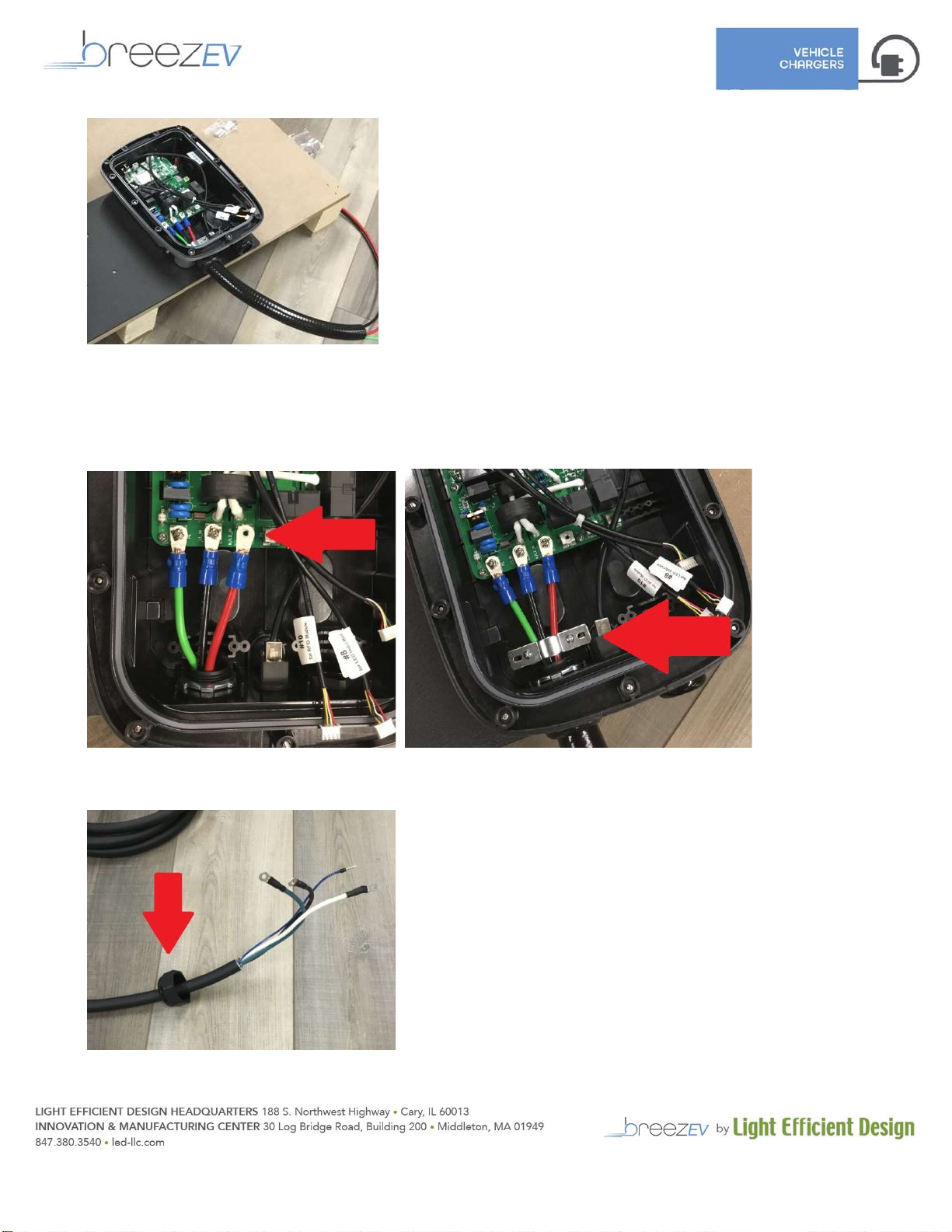
5. Pass the incoming power wires through the liquid tight and into the charger housing.
6. Attach the 3 incoming power wires like shown to the terminal block inside the charger housing using the provided
screws. Tighten down to 10lbf/in. Install the wire strain relief clamp to ensure that the wires cannot be pulled out of
the charger.
7. Slide the other end of the cable gland onto the charging cable and slide the cable through the cable gland already
mounted on the charger housing. Tighten down the gland with pliers or wrenches.
12 July 2023 Page | 15
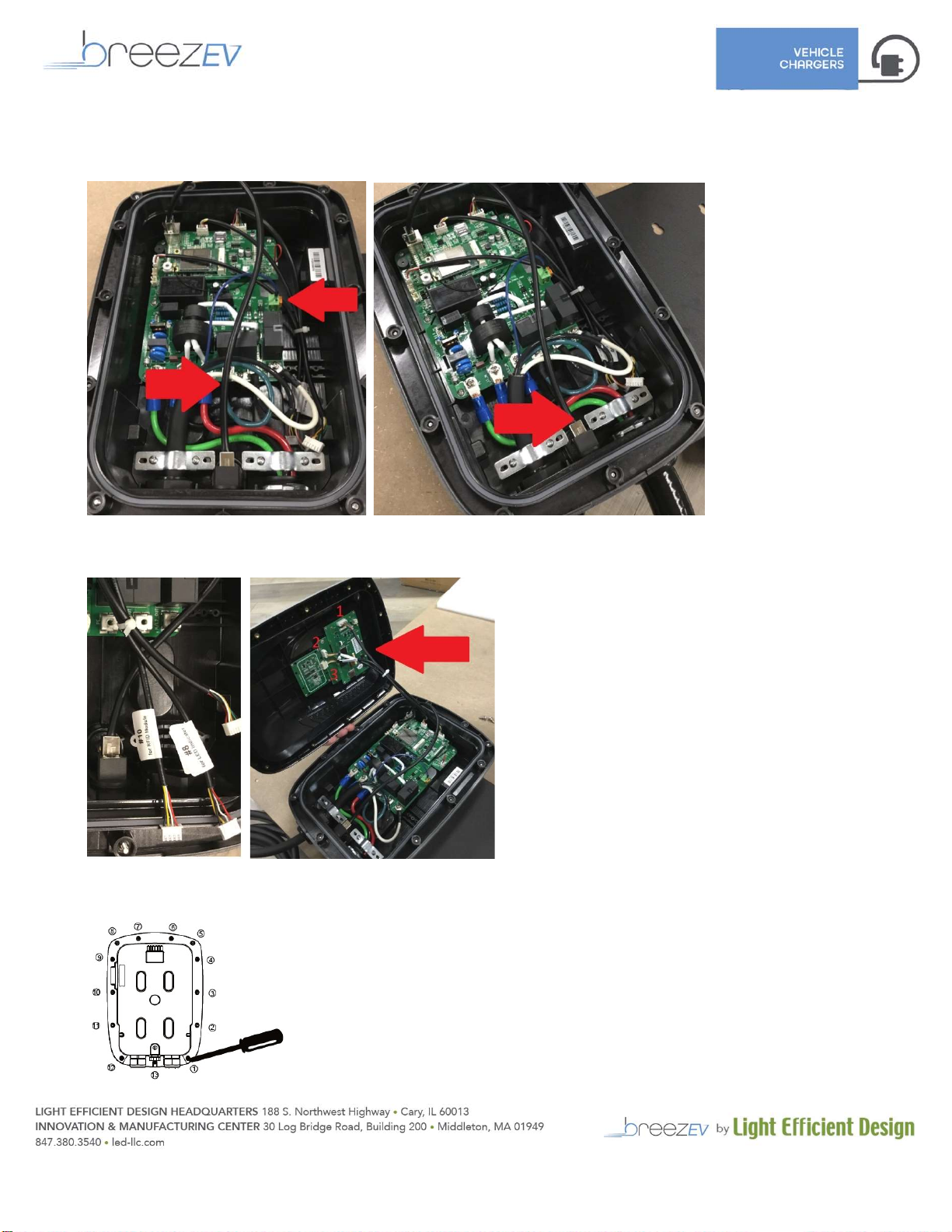
8. Connect the white, green, and black wires to the terminal block as shown with provided screws. Tighten down to
10lbf/in. Plug the blue communication wire into the green communication terminal as shown. Install the wire strain
relief clamp to ensure that the wires cannot be pulled out of the charger.
9. Before closing the charger housing, plug the 3 white connectors into the front cover connection receptacles as labeled
on each connector.
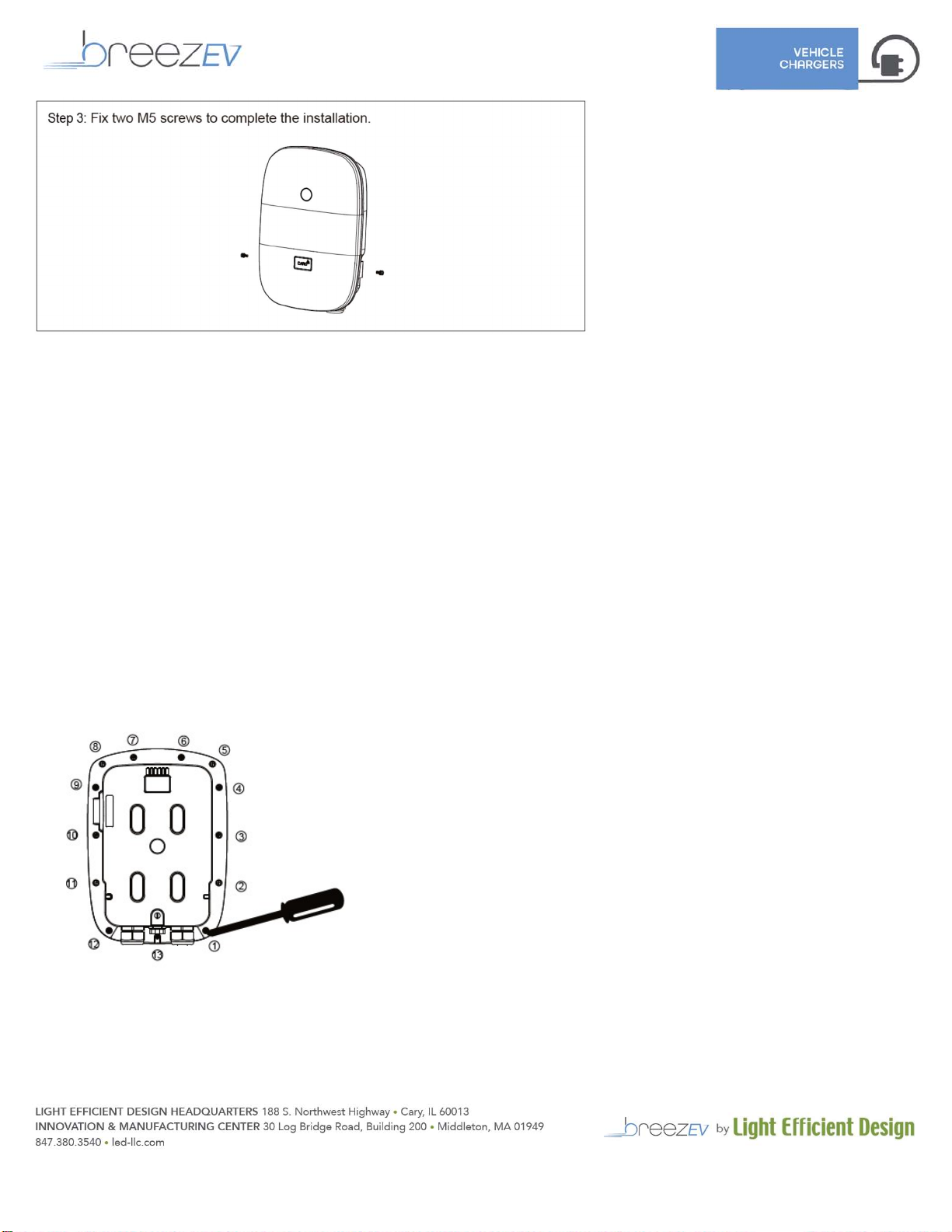
10. Close the front cover and tighten the 13 fixed screws onto the back casing. Recommended screw torque to ensure that
the gasket is properly compressed is 10lbf/in.
12 July 2023 Page | 16
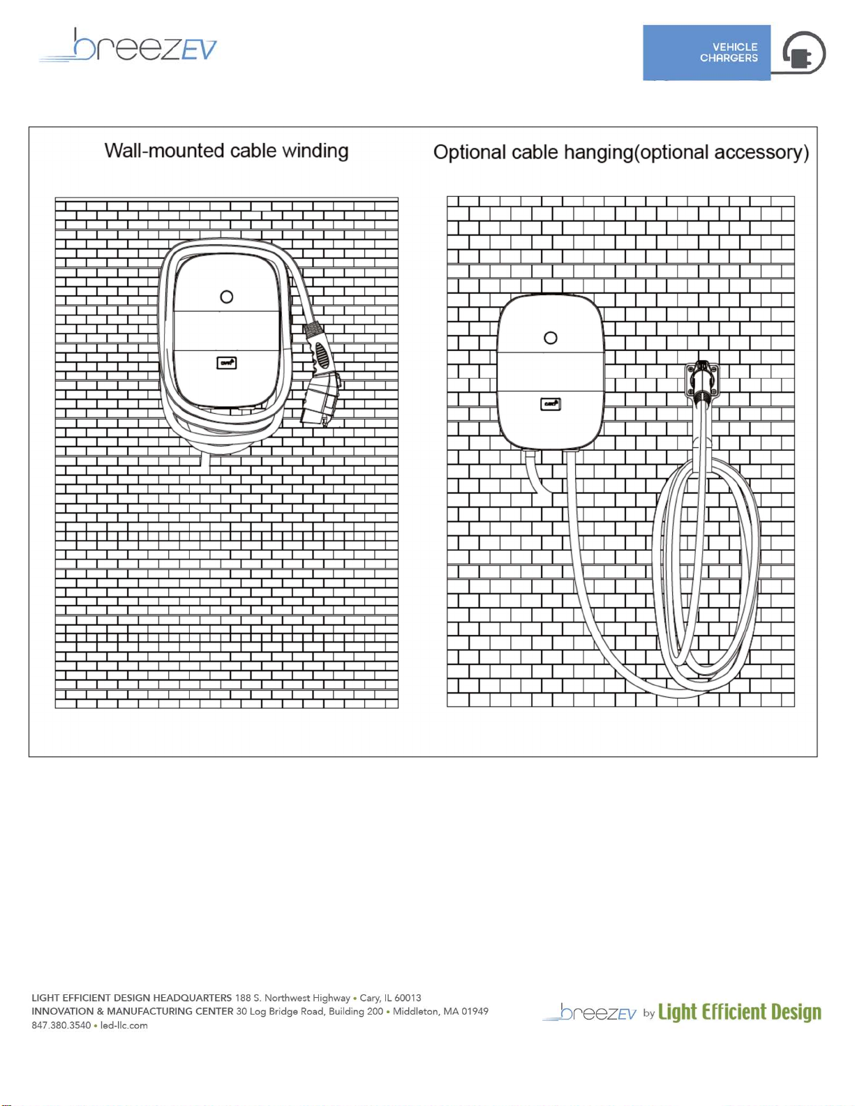
11. Attach charger to wall-mount bracket.
Example appearance after wall-mount installation is complete:

12 July 2023 Page | 17
LOWER PEDESTAL INSTALLATION (either non-cable management or cable management styles)
Concrete Pad Requirements
NOTE: The requirements below are the manufacturers minimum recommendations only. The location, dimensions, and
composition of the concrete pad for supporting the pedestal should always adhere to local building codes.
The pad must be a minimum of 18 in. square.
The pad must be a minimum of 24 in. deep.
Stub-up must be a minimum of 3 in. above the concrete pad.
Anchor J-bolts must be a minimum of 2.25 in. above the concrete pad.
If there is not a wheel stop, the center of the pedestal must be placed at least 36 in. behind the curb.
If there is a wheel stop, the center of the pedestal must be placed 12 in. behind the curb
Leveling - Hex nuts and washers can be placed on the anchor bolts below the pedestal to adjust the vertical alignment of the
pedestal should the concrete pad not be level. When leveling nuts are used, a gap will be present between the concrete pad
and pedestal base. This gap should be filled with silicone sealant. Apply silicone per manufacturers recommendations.
(Anchor J-bolts shown for new concrete pours. Use mounting hardware that comes with pedestal kit for existing concrete or
pre-set concrete pad installs).
Stainless Steel Base Plate Installation
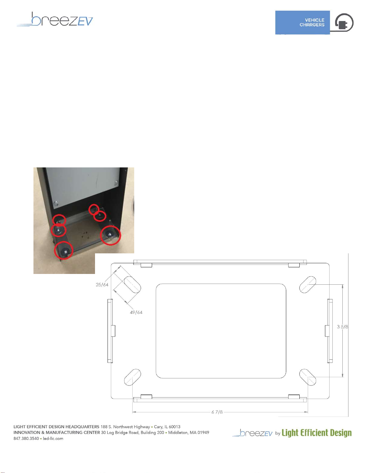
12 July 2023 Page | 18
Follow the same procedure for both non-cable management and cable-management pedestals.
When pouring new concrete, purchase a breezEV Wet Concrete Pedestal Anchor Kit (EVC-L2-ACC-ANCHOR KIT WET)
1. Using the provided template, set the 4 J-bolts in place (see below for template).
2. Ensure that at least 40in of wire extends out of the conduit.
3. Let concrete set.
When installing on existing concrete, hardware Is provided.
1. Using the provided template, mark the position of the 4 bolts (see below for template).
2. Ensure that at least 40in of wire extends out of the conduit.
3. Drill the 4 holes in the concrete, each minimum 2.2” deep.
4. Install the anchor bolts, through the base plate, with washers. Bolts must be a minimum of 2.25” above the concrete
pad.
Attaching the Pedestal Lower Section to the base plate.
1. Attach 3-sided sheet metal to the base plate using 8 x T27 screws with washers

12 July 2023 Page | 19
Installation of Chargers to the Pedestal
1. Remove the front cover of the charger housing following the directions shown on p14.
2. Remove mounting bracket from the back of the charger housing and install to pedestal using provided hardware, or in
the case of a side-by-side install, install to the side-by-side mounting bracket.
3. Install the back of the charger housing to the mounting brackets on the ground, to help hold them in place during the
following steps.
4. Install the incoming power wire liquid tight fittings and liquid tight as described on p15. IMPORTANT NOTE: If you are
performing a side-by-side install, we recommend that you use the 2 inside positions for the incoming power wires and
the 2 outer sides for the charging cable sets. This will result in a more symmetrical and cleaner install appearance. This
means that the wires will be crisscrossed inside 1 of the chargers, this is acceptable.

12 July 2023 Page | 20
5. Install the incoming power wires as described on p15-17.
6. Install the charging cable set as described on p15-17.
7. Remove the screws holding the charger housing to the wall mount bracket (either attached to the pedestal or to the
side-by-side mounting bracket). Properly attach the front charger cover to the back cover following the steps described
on p17. Re-attach the now completed charger housing assembly to the bracket.
This manual suits for next models
1
Table of contents
Other breezEV Batteries Charger manuals

Popular Batteries Charger manuals by other brands


Professional Mariner
Professional Mariner Alltech Series Owner's manual & installation guide

Sven
Sven h-113 user manual

VeriFone
VeriFone e355 Frame Type A quick start guide

Digitus
Digitus DA-10062 Quick installation guide

KUSSMAUL
KUSSMAUL 091-118 instruction manual

Douglas Battery
Douglas Battery LegaC2 DL1 owner's manual