Professional Mariner Alltech Series Troubleshooting guide
FLYBACK 10-3,20-3
PROMATIC 30-3, 50-3,
PROMATIC 21-3 (24V), 16-3(32V),
14-3(36V)
f
OWNERS MANUAL
&
INSTALLATION GUIDE
//
ALLTECH SERIES
HIGH FREQUENCYAUTOMATIC FAST CHARGERS

READ SAFETYINSTRUCTIONSBEFOREINSTALLING ANY A.C. DEVICE.
TheProfessionalMarinerFlybaclJPromaticunitsareallfullyautomatic A.C. CONNECTIONS
marinebattery chargersthat chargequickly,droptofloatand maintain, Install a circuit breaker or fuse at boat's panel. A three (3) position
condition,anddesulfateat fullcharge.Unitswill operatefrom 90to270 terminalstripisprovidedforA.C. input.Connecthot (L) andneutral
(N)
VAC, 50160 Hz single phase. toconnectionsmarked
N
andL.ConnectA.C. ground(green)toconnec-
tion marked:
1
Theyaredesignedspecificallyforthemarineenvironmentwithawater
-
-
=
resistant aluminum case with drip shieldfor effectiveheat dissipation
andcorrosionresistance.Theseunitsshould
be
~ermanentlyinstalledin
your boat and hardwired directlv to your batteries. They are designed
with three isolated outputsthat can sense and chargethree heavy duty
battery banksasneeded.
INSTALLATION:
Theseunits shouldbe mounted vertically on a bulkhead for maximum
heat dissipation.Units shouldbe securelyfastenedwith screwsor thru
bolts. Theunitsaredesignedtooperateinhigh ambient temperatures.4
-
6inchesshouldbe allowedon allsidesof unit. Thisallowsthe unit to
maintainitsowncirculationandcoolingsystemforincreasedefficiency.
FG
RecommendedA.C. fuse or breaker for boat panel:
120VAC 240 VAC
Flyback 10-3 5A 3
Flyback 20-3 10A 5
Promatic 30-3 15A
8
Promatic 50-3 20A 10
OPERATINGINSTRUCTIONS:
Theseunitsarepowerful
3
stepbatterychargers.Theyhavethecapability
todeliverfullvoltageandcurrentoverafullrangeof A.C. inputvoltages,
(90-270VAC
.)
and hertz 45 to 440
DC CONNECTIONS:
me
units
come
standard with three isolated positive posts and
one
Theseunits incorporate3 separateoutputsfor individual bank rechargean(
common
negative.
Boots
areincluded
to
cover
D.~.
connections.
con-
control.Thebuilt-inovervolfageprotectionshutsdown theunitif thevoltagt
suitwirechartforcorrectD.C. wiresize(ABYC3%wirechartavailable goes too high. (16.5 VDC)
for longer
runs).
If negatives
are
common
On
the
One
These units feature
a
built-in indicatorand
a
dualcolor power
negativeisrequiredfromthechargertothebatteries.Looseconnections
LED.
When
the
charger
is
activated,
he
LED
will
be
RED, indicatingcharge,
will damageyour charger and
/
or your boat. isinfast charge mode. Aftertheabsorptioncycleiscomplete(approx3how
after battery reaches .I volt under high setting), the light will change tc
1)Connect positive #1to battery bank #I positive. GREEN, indicatingthe chargerisin float mode.
2) Connect positive#2 to battery bank #2 positive.
3) Connect positive#3 to battery bank #3 positive.
*
The fan istemperaturecontrolled and will only come on when needed.
4) Connect common negativeto battery.
*
see diagram
Length of conductor is from chargerto battery then back to charger.
10-3.14-3.16-1
m#
u
-
20'
-
25'
3!
AWG
14
12 10 10 10
Metric
2
3
5
5
5
for
30-3,
1(Y
-
LY
-
20'
AWG
10 8
6
Metric
5
8
13
6 6
4
Metric
13 13 19
*
1
foot equals
.3048
meters
NOTE: Openvoltagesatthechargeronfastchargewill
be
14.6to 14.8
Acid batteries to compensate for voltage drop in wires. Read voltage a
batteries, adjustfor longer runs.
OVP
-
Runawayalternators,otherequipmentorlooseconnectionscouldcausc
systemto exceed the 16.5VDC OvervoltageProtectionsetting.(Fastchargc
lightwill
be
onwithnovoltageriseatbatteryandnoamperageonindicator.)I
the charger shutsdown, unplug charger and remove the D.C. negative wire
Leavedisconnectedfor 3 minutes thenreconnect thenegativewire.
This
wil
reset the charger.
Thechargeralsohasanovertemperatureshutdown.Temperaturesover 140'1
willshutdownunit.Unitwill automaticallyresetwhenloadorambien
temperaturedecreases.
AD.C. output fuse is on the D.C. negative. It isnormallyblown only when
i
battery is installed backwards. This fuse should not blow undq norma
operation. To checkthe fuse, turn off the A.C. to charger and disconnect th~
D.C.negativeoutputfromcharger. Removedripshield (4screws)
&
uppersi:
(6)screwsonendplate (withA.C. terminal stripandoutputstuds). Becarefu
nottopull outLEDplugandmeterleadsonfrontofcharger.Thefuseislocatec
onthecircuitboardneartheD.C. output(fuseisignitionprotected,automotiv~
NOTE:
If unit is used for single or dual battery bank applications, connect
units
are
set
up
for
~~~dl~~idoperation.
T~
switch to
~~1
cell
se
unused posts to a used post. If unused post is left unconnected it can reduce
diagram at right
of
page.
charger performance.
Dip switch and two potentiometersare located on the circuit board at th
Any unit used to its maximum potential,and always
the
50-39
dripshieldendabovethetransformer. Remove4screwstoremovedripshielc
should
be
installed in the upright position.
NOTE:
The
50-3
has two
(2)
separate boards.
Pull
AC
fuses oi
opposite board to adjust voltage, or send to factory for no charg
adjustment.Switchboth dipswitches for gel batteries.
-
-
-
7++-
White
N
Black
CoMMON
NEGATIVEr
\
I
I
LEADIACID
1
ON
2
OFF
PCsw
A
12
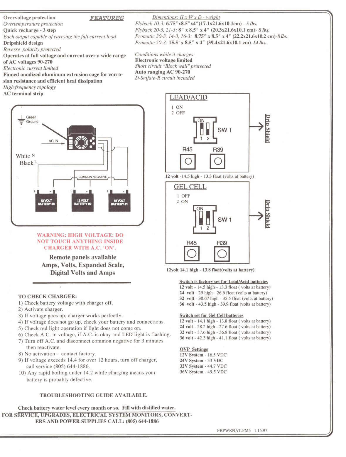
Ovewoltageprotection
A!zEumM
Dimentions:
H
x
Wx
D
-
weight
3
Overtemperatureprotection Flyback 10-3:
6.75"x8.5"~4"(17.1x21.6x10.lcm)
-
5
Ibs.
Quick recharge
-
3 step
Flyback 20-3, 21-3:
8"x 8.5" x 4" (203x21.6x10.1 cm)- 8
Ibs.
Each output capable of carrying thehllcurrent load Promatic 30-3, 14-3,
16-3:
8.75" x85"
x
4" (22.2x21.6x10.2 cm)-8
Ibs.
Dripshield design
Promatic 50-3:
15.5"~8.5" x4" (39.4x21.6x10.1 cm)-I4
Ibs.
Reverse polarity pretected
Operatesatfull voltage and current over a wide range
Conditionswhile it charges
of AC voltages90-270 Electronicvoltagelimited
Electronic currentlimited Short circuit "Blockwal1"protected
Finned anodized aluminum extrusioncageforcorro- Auto ranging AC 90-270
sion resistanceand efficientheat dissipation
D-SuEfate-Rcircuit included
Highfrequency topology
AC terminal strip
FBPWRNAT.PM5
1.15.97
#
12volt
-14.5
high
-
13.3
float
(volts
at
battery)
WARNING: HIGH VOLTAGE: DO
NOT TOUCH ANYTHING INSIDE
CHARGER WITH A.C. 'ON'.
Remote panels available
GEL CELL
1
OFF
2
ON
12
Amps, Volts, Expanded Scale,
frj
DigitalVoltsand Amps
l2volt 14.1
high
-
13.8 float(voltsat battery)
I 12volt
-
14.5
high
-
13.3
float
(
volts
at
battery)
24 volt
-
29
high
-
26.6
float
(volts
at
battery)
TOCHECK CHARGER:
32 volt
-
38.67
high
-
35.5
float
(volts
at
battery)
1)Check battery voltage with charger off.
36
volt
-
43.5
high
-
39.9
float
(volts
at
battery)
2) Activate charger.
3) If voltage goes up, charger works perfectly.
for
Gel
Cell
batteries
4)
If voltage does not go up, check your battery and connections.
12volt
-
14.1
high
-
13.8
float
(
volts
at
battery)
5)
Check red light operation if light does not come on.
24 volt
-
28.2
high
-
27.6
float
(
volts
at
battery)
6) Check A.C. in voltage, if A.C. is okay and
LED
light is flashing.
32
-
37.6
high
-
36.8
float
at
battery)
36 volt
-
42.3
high
-
41.1
float
(
volts
at
battery)
7) Turn
off A.C. and disconnect common negative for 3 minutes
then reactivate.
QVP
!wings
8) No activation
-
contact factory.
12V
System
-
16.5
VDC
9)
If voltage exceeds 14.4for over 12 hours, turn off charger,
24V
System
-
33
VDC
call service (805) 644-1886.
32V
System
-
44.7
VDC
10) Any rapid boiling under 14.2while charging means your
36V
System
-
49.5
VDC
battery is probably defective.
TROUBLESHOOTINGGUIDE AVAILABLE.
Checkbattery water level every month or
so.
Fillwith distilled water.
FOR SERVICE, UPGRADES, ELECTRICAL SYSTEMMONITORS, CONVERT-
ERS AND POWER SUPPLIESCALL: (805) 644-1886

PROFESSIONALMARINER ONE-YEAR LIMITED
WARRANTY
&
LIFETIMEREPAIR POLICY
Each product is guaranteed against defects in material and workmanship to the
original consumer in normal use for one full year after purchase at no charge except
shipping.
Each serialnumbered product has an additionalrepair adjustmentprovision afterthe
full year limited warranty that limits the maximum charge for a factory repair to the
original consumer to 1160th of the retail price times the number of months after
purchaseoruptoamaximumof 50%of current retail price, after30monthsof service,
plus shipping.
*Warranty and repair adjustment calculated from manufacture date if not registered
within 2 weeks of sale.
"Warranty void if unauthorized repairs attempted.
*Customer responsible for return shipping damage and shipping costs must be
prepaid both ways.
"Cosmetic repairs done at owner's request and expense.
Purchase orother acceptance of the product shall be on the condition and agreement
that Professional Mariner SHALL NOT BE LIABLE FOR INCIDENTAL OR
CONSEQUENTIAL DAMAGES OF ANY KIND. (some states do not allow the
exclusion or limitation of incidental or consequential damages, sothe above limita-
tion or exclusion may not apply to you.) This warranty is made in lieu of all other
obligations or liabilities on the part of Professional Mariner. Professional Mariner
neither assumesnor authorizesany person for itorany other obligation or liability in
connection with the sale of this product.
To make a claim under warranty, write directly to Professional Mariner, 2970
SeaborgAve., Ventura, CA93003, identifyingtheproduct andgivingitslocation and
followthecompany's returninstructionswhichwillthenbeprovided by thecompany.
Professional Mariner will make its best efforts to repair or replace the product, if
found to be defective within the terms of this warranty within thirty (30) days after
return of theproduct to the company. ProfessionalMariner will shipthe repaired, or
replaced product back to the purchaser at owner's expense.
This warranty gives you specific legal rights, and you may also have other rights
which vary from state to state.
This warranty is in lieu of all other expressed or implied.
Professional Mariner Inc. -2970 Seaborg Ave., Ventura, CA 93003
Tel: (805) 644-1886 Fax: (805) 644-1895
This manual suits for next models
7
Table of contents


